EP1019982B1 - Element de connecteur coaxial comportant un raccord pour relier le conducteur central d'un cable coaxial au contact central de l'element de connecteur - Google Patents
Element de connecteur coaxial comportant un raccord pour relier le conducteur central d'un cable coaxial au contact central de l'element de connecteur Download PDFInfo
- Publication number
- EP1019982B1 EP1019982B1 EP99936656A EP99936656A EP1019982B1 EP 1019982 B1 EP1019982 B1 EP 1019982B1 EP 99936656 A EP99936656 A EP 99936656A EP 99936656 A EP99936656 A EP 99936656A EP 1019982 B1 EP1019982 B1 EP 1019982B1
- Authority
- EP
- European Patent Office
- Prior art keywords
- connector element
- contact
- central
- fork
- coaxial cable
- Prior art date
- Legal status (The legal status is an assumption and is not a legal conclusion. Google has not performed a legal analysis and makes no representation as to the accuracy of the status listed.)
- Expired - Lifetime
Links
Images


Classifications
-
- H—ELECTRICITY
- H01—ELECTRIC ELEMENTS
- H01R—ELECTRICALLY-CONDUCTIVE CONNECTIONS; STRUCTURAL ASSOCIATIONS OF A PLURALITY OF MUTUALLY-INSULATED ELECTRICAL CONNECTING ELEMENTS; COUPLING DEVICES; CURRENT COLLECTORS
- H01R4/00—Electrically-conductive connections between two or more conductive members in direct contact, i.e. touching one another; Means for effecting or maintaining such contact; Electrically-conductive connections having two or more spaced connecting locations for conductors and using contact members penetrating insulation
- H01R4/28—Clamped connections, spring connections
-
- H—ELECTRICITY
- H01—ELECTRIC ELEMENTS
- H01R—ELECTRICALLY-CONDUCTIVE CONNECTIONS; STRUCTURAL ASSOCIATIONS OF A PLURALITY OF MUTUALLY-INSULATED ELECTRICAL CONNECTING ELEMENTS; COUPLING DEVICES; CURRENT COLLECTORS
- H01R9/00—Structural associations of a plurality of mutually-insulated electrical connecting elements, e.g. terminal strips or terminal blocks; Terminals or binding posts mounted upon a base or in a case; Bases therefor
- H01R9/03—Connectors arranged to contact a plurality of the conductors of a multiconductor cable, e.g. tapping connections
- H01R9/05—Connectors arranged to contact a plurality of the conductors of a multiconductor cable, e.g. tapping connections for coaxial cables
-
- H—ELECTRICITY
- H01—ELECTRIC ELEMENTS
- H01R—ELECTRICALLY-CONDUCTIVE CONNECTIONS; STRUCTURAL ASSOCIATIONS OF A PLURALITY OF MUTUALLY-INSULATED ELECTRICAL CONNECTING ELEMENTS; COUPLING DEVICES; CURRENT COLLECTORS
- H01R2103/00—Two poles
Definitions
- the present invention relates to a coaxial connector element comprising a fitting to connect the central conductor of a coaxial cable to the central contact of the element connector.
- a coaxial connector element has a central contact and a external contact.
- the central contact is intended to be connected to the central conductor of a coaxial cable and the external contact, to the external conductor of the coaxial cable, which is generally a braid ensuring earthing.
- the central contact is soldered by its rear end to the central conductor, while the external contact, or the body of the connector element to which it is connected, is crimped on the braid.
- the crimping of the braid poses no particular difficulty and gives almost always satisfaction.
- the connector can only snap into place with the central contact if the latter is suitably oriented, that is to say has the space separating the two arms of its fork opposite the radial opening.
- a coaxial connector element intended to be mounted at the end of a coaxial cable comprising a central conductor and an external conductor, the connector element comprising a central contact having an axis longitudinal and comprising a rear end connected to the central conductor of the cable coaxial and a front end arranged for the connection of the connector element with an additional connector element, an external contact connected to the external conductor of the coaxial cable and a fitting mounted on the central conductor of the coaxial cable.
- the connector and the rear end of the central contact are shaped to snap together.
- the snap-in can only be done if the fitting and the rear end of the central contact are brought together in an orientation which corresponds to the snap position.
- the present invention aims to provide a connector element in which latching can take place even when the fitting comes into contact with the end rear of the central contact in a position where it is angularly offset from its normal snap position.
- the characteristics of the connector element according to the invention are the subject of claim 1.
- the connector according to the invention has the advantage, compared to the known fitting, that it clicks into place with the central contact of the connector element ensured regardless of the angular position of the central contact, which can thus be free to rotate around its axis.
- the connector element is elbow. It then comprises a body constituted by a substantially connecting part cylindrical, in which the central contact and the external contact are housed, and by a cable connection part also substantially cylindrical, provided with a sleeve radial for cable entry.
- the housing of the coupling fork is delimited by two cylindrical recesses facing each other, whose axes are parallel to the plane of separation of the two arms and which are each produced on an inner face of each fork arms.
- the diameters of the cylindrical recesses are less than diameter of the groove of the central contact, which makes it possible to concentrate the pressures of contact between the elastic arms of the fork and the groove on the sharp edges of the recesses, so as to avoid the formation of oxides on the contact surfaces, by limitation of the quantity of oxidizing gases which can infiltrate between said surfaces of contact.
- each arm of the fork is arranged in a point so as to impart a torque to the connector and, consequently, to the central conductor of the cable, if the fitting comes into contact with the groove of the central contact being angularly offset from its normal position snap.
- each fork leg is delimited by two cylindrical recesses with axes perpendicular to the plane of separation of the two arms and located on either side of a median plane of the fitting perpendicular to the plane of separation of the two arms of the fork.
- the pointed shape of the fork arms is particularly useful because insertion into the cable connection part of the fitting mounted at the end of the cable coaxial, performed blind, i.e. with loss of visual control of the correct orientation of the fitting relative to the groove of the central contact.
- edges of the points serve as angular guide cams of the fitting on the throat.
- the torque thus created can be enough to automatically drive the correct positioning of the fitting, in the event of a very small angular offset, the conductor center of the cable then absorbing the offset by twisting slightly in the coaxial cable, either encourage the operator who installs the fitting in the connector element to do turn the cable to bring the fitting into the correct angular position.
- connection is obtained by cutting and rolling.
- the connector is obtained by machining.
- the connector is crimped onto the conductor center of the coaxial cable.
- the connector element according to the invention may include a bent body without opening on its opposite face at its connection face.
- the connector element 1 shown in the drawing comprises a body in two parts namely a cylindrical connection part 2 and a connection part of cable 3 which extends the connection part to its rear part and includes an anvil sleeve radially projecting near the rear face 5 of the connector element.
- connection part of the connector element will not be explained here because the invention applies to all kinds of connection interfaces and is not therefore not limited to the interface shown in the drawing.
- the cable connection part 3 of the body is crimped at 9 on the part of connection and defines, behind the connection part 2, a housing 10 for the rear end 11 of the central contact 8 and for a connector 12 intended to be subjected to the end of the central conductor (not shown) of a coaxial cable (not shown).
- the connector 12 extends radially relative to the connection part 2 and coaxial with the anvil sleeve 4 of the connection part.
- the coaxial cable penetrates, in known manner, into the body of the connector element as follows.
- the braid of the cable which constitutes its external ground conductor, is applied to the external wall of the anvil sleeve 4 and is crushed there by a crimping sleeve 13 which surrounds the anvil sleeve 4.
- the central conductor and its sheath enter the anvil sleeve 4 and the fitting 12 is crimped onto the central conductor.
- the central contact 8 comprises, at its front end 14, an elastic zone which is able to move aside to force-fit or snap into place, depending on the type of interface considered, on the central contact of a connector element complementary.
- the central contact 8 has different shoulders and flanges, in its region median, which allow its retention inside the tubular insulation 7.
- the central contact At its rear end 11, the central contact has a groove 15 of revolution terminated by a flat head 16.
- the shape of this head makes it possible to adapt the line in impedance.
- the connector 12 which is shown in elevation in Figures 3 and 4, comprises a crimping part 17 at the rear, intended to be crushed on the central conductor of the cable coaxial, and an elastic part 18 at the front constituted by two arms 19 cut in a cylinder of revolution and separated by a space 20 according to a separation plane passing through the axis of the fitting.
- the two arms 19 thus separated have a slight elasticity which allows them to move away from each other.
- the elastic arms 19 of the connector have recesses 21 facing each other.
- Each obviously 21 presents a cylindrical shape with an axis parallel to the plane of separation of the elastic arms and perpendicular to the axis of the fitting.
- the two obviously cylindrical 21 facing each other define a housing substantially cylindrical intended to receive the groove of revolution 15 of the central contact 8.
- each obviously 21 is less than the diameter of the groove 15 by so that each of the recesses, once the latching has been carried out, rests on the groove by its sharp edges 22.
- the purpose of such an arrangement is to make the contact between the elastic tabs of the fitting and the groove so that oxidizing gases present in the ambient air does not come to create an oxidation of the surfaces in mutual support of the fitting and contact.
- each elastic tab of the connector is shaped as a point to constitute exhaust manifolds of the connector in the event of poor angular presentation of the latter in front of the throat, as will be explained.
- Each point of an elastic arm is delimited by concave shapes cylindrical 24 with an axis perpendicular to that of the housing provided between the elastic tabs.
- Each concave shape 24 is located on either side of a median plane of the connector.
- the fitting Once the fitting is properly oriented, it can continue to progress towards the front until the groove clicks into the housing provided between the two arms elastic, as shown in figure 5.
- the first circumstance is that in which the fitting has a slight angular phase shift from its snap position on the groove.
- the torque exerted by the circular ramps of the tips is enough to twist the central conductor of the cable and the connector is oriented correctly without the operator does not have to change the orientation of the cable.
- the second circumstance is that in which the angular phase shift of the fitting is very important.
- the torque exerted by the guide rails is transmitted, by the central conductor of the twisted cable, to the fingers of the operator who then realizes that should slightly release the cable or, better, rotate it in the right direction to allow the fitting to snap onto the groove.
Abstract
Description
- la difficulté d'utiliser la même quantité de brasure d'un élément de connecteur à l'autre, ce qui est pourtant indispensable pour obtenir une impédance toujours identique.
- la nécessité de prévoir une isolation entre la brasure et la paroi intérieure du corps de l'élément de connecteur, afin d'éviter qu'un fil de brasure résiduel ne crée un court-circuit entre le conducteur central et la masse.
- la nécessité d'accéder à l'arrière de l'élément de connecteur au moment de sa mise en place sur un câble coaxial, pour réaliser le brasage, ce qui impose la présence d'une ouverture débouchant sur l'extrémité arrière du contact central.
- la figure 1 est une vue en coupe axiale d'un élément de connecteur coaxial selon l'invention,
- la figure 2 est une vue en élévation du contact central de l'élément de connecteur de la figure 1,
- la figure 3 est une vue en élévation du raccord,
- la figure 4 est une vue de dessus de la figure 3,
- la figure 5 est une vue en perspective du raccord encliqueté sur le contact central,
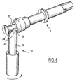
- les figures 6 à 9 représentent le contact et le raccord lors de la manoeuvre d'encliquetage.
Claims (7)
- Elément de connecteur coaxial, destiné à être monté à l'extrémité d'un câble coaxial comportant un conducteur central et un conducteur externe, l'élément de connecteur comportant :caractérisé par le fait que l'extrémité arrière (11) du contact central (8) comporte une gorge de révolution (15) de même axe que l'axe longitudinal du contact central tandis que le raccord (12) comporte une fourche élastique à deux bras (19) définissant entre eux un logement pour la gorge, l'encliquetage de la gorge dans le logement de la fourche s'effectuant par emmanchement de la gorge dans la fourche suivant une direction perpendiculaire à l'axe longitudinal du contact, et que l'extrémité libre (23) de chaque bras de la fourche est agencée en pointe délimitée par deux évidements cylindriques (24) d'axes perpendiculaires au plan de séparation des deux bras et situés de part et d'autre d'un plan médian du raccord perpendiculaire au plan de séparation des deux bras de la fourche, de manière à imprimer un couple de rotation au raccord, si le raccord entre en contact avec la gorge du contact central en étant décalé angulairement par rapport à sa position normale d'encliquetage, pour le faire tourner dans une position dans laquelle ladite gorge peut s'engager dans ladite fourche.un contact central (8) ayant un axe longitudinal et comprenant une extrémité arrière (11) reliée au conducteur central du câble coaxial et une extrémité avant (14) agencée pour la connexion de l'élément de connecteur avec un élément de connecteur complémentaire,un contact extérieur (6) relié au conducteur externe du câble coaxial, etun raccord (12) monté sur le conducteur central du câble coaxial,
- Elément de connecteur selon la revendication 1, caractérisé par le fait qu'il est coudé.
- Elément de connecteur selon la revendication 2, caractérisé par le fait que le logement est délimité par deux évidements cylindriques (21) en regard l'un de l'autre dont les axes sont parallèles au plan de séparation des deux bras (19), et qui sont réalisés chacun sur une face intérieure de chaque bras de la fourche.
- Elément de connecteur selon la revendication 3, caractérisé par le fait que les diamètres des évidements cylindriques (21) sont inférieurs au diamètre de la gorge (15) du contact central.
- Elément de connecteur selon l'une quelconque des revendications 1 à 4,
caractérisé par le fait que le raccord (12) est serti sur le conducteur central du câble coaxial. - Elément de connecteur selon l'une quelconque des revendications 1 à 5, caractérisé par le fait qu'il comporte un corps coudé dépourvu d'ouverture sur sa face (5) opposée à sa face de connexion.
- Elément de connecteur selon l'une quelconque des revendications 1 à 6, caractérisé par le fait que le raccord (12) est obtenu par découpe et roulage.
Applications Claiming Priority (3)
| Application Number | Priority Date | Filing Date | Title |
|---|---|---|---|
| FR9809863 | 1998-07-31 | ||
| FR9809863A FR2781934B1 (fr) | 1998-07-31 | 1998-07-31 | Element de connecteur coaxial comportant un raccord pour relier le conducteur central d'un cable coaxial au contact central de l'element de connecteur |
| PCT/FR1999/001897 WO2000008723A1 (fr) | 1998-07-31 | 1999-07-30 | Element de connecteur coaxial comportant un raccord pour relier le conducteur central d'un cable coaxial au contact central de l'element de connecteur |
Publications (2)
| Publication Number | Publication Date |
|---|---|
| EP1019982A1 EP1019982A1 (fr) | 2000-07-19 |
| EP1019982B1 true EP1019982B1 (fr) | 2003-10-08 |
Family
ID=9529275
Family Applications (1)
| Application Number | Title | Priority Date | Filing Date |
|---|---|---|---|
| EP99936656A Expired - Lifetime EP1019982B1 (fr) | 1998-07-31 | 1999-07-30 | Element de connecteur coaxial comportant un raccord pour relier le conducteur central d'un cable coaxial au contact central de l'element de connecteur |
Country Status (8)
| Country | Link |
|---|---|
| US (1) | US6287144B1 (fr) |
| EP (1) | EP1019982B1 (fr) |
| JP (1) | JP2003526872A (fr) |
| CN (1) | CN1110111C (fr) |
| AU (1) | AU5167899A (fr) |
| DE (2) | DE1019982T1 (fr) |
| FR (1) | FR2781934B1 (fr) |
| WO (1) | WO2000008723A1 (fr) |
Cited By (1)
| Publication number | Priority date | Publication date | Assignee | Title |
|---|---|---|---|---|
| WO2009100801A1 (fr) * | 2008-02-12 | 2009-08-20 | Rosenberger Hochfrequenztechnik Gmbh & Co. Kg | Connecteur enfichable coaxial coudé |
Families Citing this family (32)
| Publication number | Priority date | Publication date | Assignee | Title |
|---|---|---|---|---|
| US6379162B1 (en) * | 2000-07-27 | 2002-04-30 | Delphi Technologies, Inc. | Electrical connector system |
| US20030224658A1 (en) * | 2002-05-30 | 2003-12-04 | Richard Koch | Electrical connector |
| TW555194U (en) * | 2002-11-29 | 2003-09-21 | Hon Hai Prec Ind Co Ltd | Electrical connector |
| US6860761B2 (en) * | 2003-01-13 | 2005-03-01 | Andrew Corporation | Right angle coaxial connector |
| CN101395763A (zh) * | 2006-02-28 | 2009-03-25 | 胡贝尔和茹纳股份公司 | 用于同轴电缆的折弯的插接连接器 |
| US7766659B2 (en) * | 2006-05-18 | 2010-08-03 | Masprodenkoh Kabushikikaisha | Series unit with moveable terminal(s) for connection of coaxial cables |
| US7419403B1 (en) * | 2007-06-20 | 2008-09-02 | Commscope, Inc. Of North Carolina | Angled coaxial connector with inner conductor transition and method of manufacture |
| DE102007057443A1 (de) * | 2007-11-29 | 2009-06-04 | Robert Bosch Gmbh | Winkelstecker für Koaxialkabel |
| US7896655B1 (en) * | 2009-08-14 | 2011-03-01 | Tyco Electronics Corporation | Multi-port connector system |
| DE102009043516A1 (de) * | 2009-09-30 | 2011-04-07 | Tyco Electronics Amp Gmbh | Zweiteiliges Kontaktelement für Hochspannungssteckverbinder |
| EP2367239A1 (fr) * | 2010-03-16 | 2011-09-21 | Tyco Electronics Services GmbH | Connecteur électrique avec broche de contact et broche d'interconnexion |
| EP2739346B1 (fr) * | 2011-08-05 | 2016-12-28 | Advanced Bionics AG | Interconnexions de processeur de son, ensembles casques et leurs procédés de fabrication |
| US8641447B2 (en) * | 2011-12-20 | 2014-02-04 | Tyco Electronics Corporation | Coaxial connector |
| US9054471B2 (en) | 2012-02-03 | 2015-06-09 | Megaphase, Llc | Coaxial angled adapter |
| US8992250B1 (en) | 2013-03-15 | 2015-03-31 | Megaphase, Llc | Clockable cable adapter |
| DE202013006067U1 (de) * | 2013-07-05 | 2013-08-12 | Rosenberger Hochfrequenztechnik Gmbh & Co. Kg | Steckverbinder |
| CN103872594B (zh) * | 2014-03-24 | 2016-06-29 | 中国能源建设集团广东省电力设计研究院有限公司 | ±160kV柔性直流换流站直流场导体结构 |
| US9099797B1 (en) * | 2014-04-25 | 2015-08-04 | Tyco Electronics Corporation | Electrical connector |
| US20160226202A1 (en) * | 2015-02-03 | 2016-08-04 | Commscope Technologies Llc | Right angle coaxial cable and connector assembly |
| US9614302B2 (en) | 2015-02-04 | 2017-04-04 | Commscope Technologies Llc | Right angle coaxial cable and connector assembly |
| US9853385B1 (en) | 2015-02-19 | 2017-12-26 | Ohio Associated Enterprises, Llc | Axial compliant compression electrical connector |
| US10074923B1 (en) * | 2015-02-19 | 2018-09-11 | Ohio Associated Enterprises, Llc | Axial compliant compression electrical connector |
| US9929527B2 (en) * | 2015-03-16 | 2018-03-27 | Commscope Technologies Llc | Right angle coaxial cable and connector assembly and method of forming same |
| US9966702B2 (en) * | 2015-05-01 | 2018-05-08 | Commscope Technologies Llc | Coaxial cable connector interface for preventing mating with incorrect connector |
| US9762001B2 (en) * | 2016-02-01 | 2017-09-12 | Delphi Technologies, Inc. | Right angled coaxial electrical connector and methods for verifying proper assembly thereof |
| US10186817B2 (en) | 2016-09-20 | 2019-01-22 | Commscope Technologies Llc | Right angle coaxial connector assembly |
| US10468837B2 (en) | 2016-09-27 | 2019-11-05 | Te Connectivity Corporation | Coaxial connector assembly |
| CN110197987A (zh) * | 2018-02-27 | 2019-09-03 | 康普技术有限责任公司 | 具有两体式内导体的弯式射频同轴连接器 |
| US10476191B2 (en) | 2018-02-28 | 2019-11-12 | Ohio Associated Enterprises, Llc | Forked electrical contact pair with elastic tail |
| CN115799928A (zh) * | 2018-03-14 | 2023-03-14 | 康普技术有限责任公司 | 同轴偏置t型连接器 |
| DE102020116736A1 (de) * | 2020-06-25 | 2021-12-30 | Te Connectivity Germany Gmbh | Steckverbinder für ein Steckverbindersystem, Steckverbindersystem und Verfahren zum Herstellen eines Steckverbindersystems |
| DE102021100807B3 (de) | 2021-01-15 | 2022-02-03 | Te Connectivity Germany Gmbh | Kontakteinrichtung, insbesondere Koaxial-Kontakteinrichtung |
Family Cites Families (5)
| Publication number | Priority date | Publication date | Assignee | Title |
|---|---|---|---|---|
| DE1665758B1 (de) * | 1966-09-27 | 1971-07-01 | Siemens Ag | Koaxialer Verbindungsstecker fuer Geraete der Nachrichtentechnik |
| US3432798A (en) * | 1967-08-10 | 1969-03-11 | Sealectro Corp | Right angle connectors |
| US4691976A (en) * | 1986-02-19 | 1987-09-08 | Lrc Electronics, Inc. | Coaxial cable tap connector |
| GB9507151D0 (en) * | 1995-04-06 | 1995-05-31 | Amp Gmbh | Right angled coaxial connector |
| US5597323A (en) * | 1995-08-07 | 1997-01-28 | The Whitaker Corporation | RF connector jack and plug assembly |
-
1998
- 1998-07-31 FR FR9809863A patent/FR2781934B1/fr not_active Expired - Fee Related
-
1999
- 1999-07-30 DE DE1019982T patent/DE1019982T1/de active Pending
- 1999-07-30 AU AU51678/99A patent/AU5167899A/en not_active Abandoned
- 1999-07-30 DE DE69911904T patent/DE69911904D1/de not_active Expired - Lifetime
- 1999-07-30 US US09/509,609 patent/US6287144B1/en not_active Expired - Fee Related
- 1999-07-30 EP EP99936656A patent/EP1019982B1/fr not_active Expired - Lifetime
- 1999-07-30 WO PCT/FR1999/001897 patent/WO2000008723A1/fr active IP Right Grant
- 1999-07-30 JP JP2000564267A patent/JP2003526872A/ja active Pending
- 1999-07-30 CN CN99801244A patent/CN1110111C/zh not_active Expired - Fee Related
Cited By (1)
| Publication number | Priority date | Publication date | Assignee | Title |
|---|---|---|---|---|
| WO2009100801A1 (fr) * | 2008-02-12 | 2009-08-20 | Rosenberger Hochfrequenztechnik Gmbh & Co. Kg | Connecteur enfichable coaxial coudé |
Also Published As
| Publication number | Publication date |
|---|---|
| CN1274477A (zh) | 2000-11-22 |
| DE69911904D1 (de) | 2003-11-13 |
| CN1110111C (zh) | 2003-05-28 |
| AU5167899A (en) | 2000-02-28 |
| US6287144B1 (en) | 2001-09-11 |
| JP2003526872A (ja) | 2003-09-09 |
| EP1019982A1 (fr) | 2000-07-19 |
| FR2781934A1 (fr) | 2000-02-04 |
| WO2000008723A1 (fr) | 2000-02-17 |
| DE1019982T1 (de) | 2001-02-08 |
| FR2781934B1 (fr) | 2000-10-06 |
Similar Documents
| Publication | Publication Date | Title |
|---|---|---|
| EP1019982B1 (fr) | Element de connecteur coaxial comportant un raccord pour relier le conducteur central d'un cable coaxial au contact central de l'element de connecteur | |
| EP0663706B1 (fr) | Connecteur coaxial microminiature à verrouillage par encliquetage | |
| FR2760137A1 (fr) | Connecteur electrique coaxial | |
| EP1054479A1 (fr) | Dispositif pour relier électriquement une ligne coaxiale à une carte de circuit imprimé | |
| FR2758662A1 (fr) | Element de connecteur electrique coaxial a contact mobile et connecteur electrique coaxial comprenant un tel element de connecteur | |
| FR2717623A1 (fr) | Connecteur pour câble coaxial. | |
| FR2701170A1 (fr) | Contact électrique femelle à lame souple. | |
| FR2487478A1 (fr) | Connecteur orientable | |
| EP0574293B1 (fr) | Borne femelle de contact électrique et connecteur en faisant application | |
| EP1039587A1 (fr) | Elément de connecteur destiné à être monté sur un câble électrique à conducteur externe spiralé et son procédé de montage | |
| EP0908965B1 (fr) | Borne de connexion à serrage automatique | |
| CA2296201C (fr) | Element de connecteur pour fibre optique | |
| CH631293A5 (fr) | Contact electrique. | |
| EP1531525B1 (fr) | Serre-câble à plage de serrage èlargie et bloc de jonction muni d'un tel serre-câble | |
| EP0121637B1 (fr) | Embout droit de raccordement électrique | |
| EP1672740B1 (fr) | Borne de connexion rapide pour interrupteurs et prises de courant | |
| EP0664578A1 (fr) | Connecteur pour câble coaxial | |
| EP0172779B1 (fr) | Connecteur electrique multipolaire | |
| EP0884806B1 (fr) | Connecteur électrique à sécurité de contact améliorée | |
| FR2691584A1 (fr) | Connecteur électrique et dispositif de connexion électrique comportant au moins un tel connecteur. | |
| CA2154429A1 (fr) | Connecteur electrique haute frequence realisant egalement une fonction de commutation | |
| EP0340066B1 (fr) | Connecteur électrique | |
| FR2751482A1 (fr) | Dispositif pour la realisation d'une epissure | |
| FR2806216A1 (fr) | Dispositif de connexion rapide d'un cable a une borne d'une source d'alimentation en energie electrique | |
| FR2633456A1 (fr) | Connecteur autodenudant pour conducteur electrique |
Legal Events
| Date | Code | Title | Description |
|---|---|---|---|
| PUAI | Public reference made under article 153(3) epc to a published international application that has entered the european phase |
Free format text: ORIGINAL CODE: 0009012 |
|
| AK | Designated contracting states |
Kind code of ref document: A1 Designated state(s): AT BE CH CY DE DK ES FI FR GB GR IE IT LI LU MC NL PT SE |
|
| 17P | Request for examination filed |
Effective date: 20000721 |
|
| DET | De: translation of patent claims | ||
| 17Q | First examination report despatched |
Effective date: 20011123 |
|
| GRAH | Despatch of communication of intention to grant a patent |
Free format text: ORIGINAL CODE: EPIDOS IGRA |
|
| RIC1 | Information provided on ipc code assigned before grant |
Ipc: 7H 01R 9/05 A |
|
| GRAH | Despatch of communication of intention to grant a patent |
Free format text: ORIGINAL CODE: EPIDOS IGRA |
|
| RAP1 | Party data changed (applicant data changed or rights of an application transferred) |
Owner name: RADIALL |
|
| GRAA | (expected) grant |
Free format text: ORIGINAL CODE: 0009210 |
|
| AK | Designated contracting states |
Kind code of ref document: B1 Designated state(s): CH DE FR LI |
|
| REG | Reference to a national code |
Ref country code: CH Ref legal event code: EP |
|
| REG | Reference to a national code |
Ref country code: IE Ref legal event code: FG4D Free format text: FRENCH |
|
| REF | Corresponds to: |
Ref document number: 69911904 Country of ref document: DE Date of ref document: 20031113 Kind code of ref document: P |
|
| PG25 | Lapsed in a contracting state [announced via postgrant information from national office to epo] |
Ref country code: DE Free format text: LAPSE BECAUSE OF FAILURE TO SUBMIT A TRANSLATION OF THE DESCRIPTION OR TO PAY THE FEE WITHIN THE PRESCRIBED TIME-LIMIT Effective date: 20040109 |
|
| REG | Reference to a national code |
Ref country code: IE Ref legal event code: FD4D |
|
| PG25 | Lapsed in a contracting state [announced via postgrant information from national office to epo] |
Ref country code: LI Free format text: LAPSE BECAUSE OF NON-PAYMENT OF DUE FEES Effective date: 20040731 Ref country code: CH Free format text: LAPSE BECAUSE OF NON-PAYMENT OF DUE FEES Effective date: 20040731 |
|
| PLBE | No opposition filed within time limit |
Free format text: ORIGINAL CODE: 0009261 |
|
| STAA | Information on the status of an ep patent application or granted ep patent |
Free format text: STATUS: NO OPPOSITION FILED WITHIN TIME LIMIT |
|
| 26N | No opposition filed |
Effective date: 20040709 |
|
| REG | Reference to a national code |
Ref country code: CH Ref legal event code: PL |
|
| PG25 | Lapsed in a contracting state [announced via postgrant information from national office to epo] |
Ref country code: FR Free format text: LAPSE BECAUSE OF NON-PAYMENT OF DUE FEES Effective date: 20050331 |
|
| REG | Reference to a national code |
Ref country code: FR Ref legal event code: ST |