EP1019817B1 - Secure memory having multiple security levels - Google Patents
Secure memory having multiple security levels Download PDFInfo
- Publication number
- EP1019817B1 EP1019817B1 EP98948495A EP98948495A EP1019817B1 EP 1019817 B1 EP1019817 B1 EP 1019817B1 EP 98948495 A EP98948495 A EP 98948495A EP 98948495 A EP98948495 A EP 98948495A EP 1019817 B1 EP1019817 B1 EP 1019817B1
- Authority
- EP
- European Patent Office
- Prior art keywords
- memory
- access
- code
- security code
- zone
- Prior art date
- Legal status (The legal status is an assumption and is not a legal conclusion. Google has not performed a legal analysis and makes no representation as to the accuracy of the status listed.)
- Expired - Lifetime
Links
Images


Classifications
-
- G—PHYSICS
- G07—CHECKING-DEVICES
- G07F—COIN-FREED OR LIKE APPARATUS
- G07F7/00—Mechanisms actuated by objects other than coins to free or to actuate vending, hiring, coin or paper currency dispensing or refunding apparatus
- G07F7/08—Mechanisms actuated by objects other than coins to free or to actuate vending, hiring, coin or paper currency dispensing or refunding apparatus by coded identity card or credit card or other personal identification means
- G07F7/10—Mechanisms actuated by objects other than coins to free or to actuate vending, hiring, coin or paper currency dispensing or refunding apparatus by coded identity card or credit card or other personal identification means together with a coded signal, e.g. in the form of personal identification information, like personal identification number [PIN] or biometric data
- G07F7/1008—Active credit-cards provided with means to personalise their use, e.g. with PIN-introduction/comparison system
-
- G—PHYSICS
- G06—COMPUTING; CALCULATING OR COUNTING
- G06F—ELECTRIC DIGITAL DATA PROCESSING
- G06F11/00—Error detection; Error correction; Monitoring
-
- G—PHYSICS
- G06—COMPUTING; CALCULATING OR COUNTING
- G06F—ELECTRIC DIGITAL DATA PROCESSING
- G06F12/00—Accessing, addressing or allocating within memory systems or architectures
- G06F12/14—Protection against unauthorised use of memory or access to memory
- G06F12/1416—Protection against unauthorised use of memory or access to memory by checking the object accessibility, e.g. type of access defined by the memory independently of subject rights
- G06F12/1425—Protection against unauthorised use of memory or access to memory by checking the object accessibility, e.g. type of access defined by the memory independently of subject rights the protection being physical, e.g. cell, word, block
- G06F12/1441—Protection against unauthorised use of memory or access to memory by checking the object accessibility, e.g. type of access defined by the memory independently of subject rights the protection being physical, e.g. cell, word, block for a range
-
- G—PHYSICS
- G06—COMPUTING; CALCULATING OR COUNTING
- G06Q—INFORMATION AND COMMUNICATION TECHNOLOGY [ICT] SPECIALLY ADAPTED FOR ADMINISTRATIVE, COMMERCIAL, FINANCIAL, MANAGERIAL OR SUPERVISORY PURPOSES; SYSTEMS OR METHODS SPECIALLY ADAPTED FOR ADMINISTRATIVE, COMMERCIAL, FINANCIAL, MANAGERIAL OR SUPERVISORY PURPOSES, NOT OTHERWISE PROVIDED FOR
- G06Q20/00—Payment architectures, schemes or protocols
- G06Q20/30—Payment architectures, schemes or protocols characterised by the use of specific devices or networks
- G06Q20/34—Payment architectures, schemes or protocols characterised by the use of specific devices or networks using cards, e.g. integrated circuit [IC] cards or magnetic cards
- G06Q20/341—Active cards, i.e. cards including their own processing means, e.g. including an IC or chip
-
- G—PHYSICS
- G06—COMPUTING; CALCULATING OR COUNTING
- G06Q—INFORMATION AND COMMUNICATION TECHNOLOGY [ICT] SPECIALLY ADAPTED FOR ADMINISTRATIVE, COMMERCIAL, FINANCIAL, MANAGERIAL OR SUPERVISORY PURPOSES; SYSTEMS OR METHODS SPECIALLY ADAPTED FOR ADMINISTRATIVE, COMMERCIAL, FINANCIAL, MANAGERIAL OR SUPERVISORY PURPOSES, NOT OTHERWISE PROVIDED FOR
- G06Q20/00—Payment architectures, schemes or protocols
- G06Q20/30—Payment architectures, schemes or protocols characterised by the use of specific devices or networks
- G06Q20/34—Payment architectures, schemes or protocols characterised by the use of specific devices or networks using cards, e.g. integrated circuit [IC] cards or magnetic cards
- G06Q20/357—Cards having a plurality of specified features
- G06Q20/3576—Multiple memory zones on card
- G06Q20/35765—Access rights to memory zones
Definitions
- the present invention relates to a secured memory in accordance with the precharacterizing portion of claim 1.
- a security memory is known from GUEULLE P: 'LES E2PROM SERIE SECURISEES' ELECTRONIQUE RADIO PLANS, FR, SPE, PARIS, no. 548, 1 July 1993(1993-07-01), pages 23-28, XP000377636 ISSN: 1144-5742.
- plastic cards were embossed and had a signature line which could be used for comparison to maintain security. However, as can be imagined, this was not much of a deterrent to fraud and misuse.
- the first major security improvement was the addition of a magnetic stripe on the back of the embossed card.
- Plastic cards with a magnetic stripe are probably the most popular form of payment and information card available today.
- the memory storage provided by the magnetic stripe also permitted the recordation of far greater amounts of information than could be embossed on the face of a plastic card.
- these cards provide some level of protection, it is not all that difficult for the data stored on a magnetic stripe to be read, deleted and rewritten by anyone with access to the appropriate read/write device. Accordingly, it is less than suitable for the storage of confidential data, or for storing a value that can be used in place of currency.
- a plastic card with a secure memory was developed. These cards are known in the industry as "smart cards".
- the storage area of the secure memory is often divided into blocks of memory.
- the object of providing security to a memory is to protect against unauthorized access to and tampering with these blocks.
- the security is typically provided by some combination of both hardware and software. With a secure memory it is possible to write confidential data that cannot be read or erased, and to prevent writing of data by controlling the reading, writing and erasing with the combination of hardware and software which depend upon particular conditions to occur prior to executing these operations.
- a "smart card” with a secure memory and one which has been widely used is a telephone memory card. These cards are prepaid, and the value stored electronically in the memory is deducted during use by the appropriate amount. Of course, to prevent misuse it is necessary to prevent the user from tampering with the card to increment the stored value. If it were a magnetic stripe card, rewriting a new value to the card could be accomplished easily.
- One manner known in the art to prevent tampering with the secured memory to increment a stored value is to provide a secure code that is known only to the issuer of the card.
- a systematic attack to determine the secure code is deterred by an attempt counter that prevents further use of the card if the number of attempts to present a valid secure code exceeds a predetermined number. When a valid secure code is presented prior to the attempt counter reaching its limit, the attempt counter is reset to zero.
- Each of thcse blocks are further protected by an erase code that must he presented before the storage block can be erased. Unfortunately, these erase codes are vulnerable to systematic attack.
- a secured memory comprises a first level security zone having an access code controlling access to said secured memory prior to an issuer fuse being blown, a security code attempts counter preventing access to said secured memory when a predetermined number of attempts at matching said access code have been made prior to resetting said security code attempts counter, a plurality of application zones characterized in that each of said plurality of application zones comprising: a storage memory zone, an application security zone having an application zone access code controlling access to said storage memory zone after an issuer fuse has been blown, an application zone security code attempts counter preventing access to said application zone when a predetermined number of attempts at matching said application zone access code have been made prior to resetting said application zone security code attempts counter, an erase key partition having an erase key code controlling erase access to said storage memory zone after an issuer fuse has been blown, and an erase key attempts counter preventing erase access to said application zone when a predetermined number of attempts at matching said erase key code have been made prior to resetting said erase key attempts counter.
- At least three groups of individuals are involved in the handling of a secured memory that is incorporated into a smart card.
- the first is the manufacturer of the secured memory.
- the second is the card manufacturer that incorporates the secured memory into the smart card and then distributes the smart card to the end user. (Often the card manufacturing and card issuer or distributor roles are performed by different groups of individuals).
- the third is the user of the secured memory which has obtained the product from the issuer or distributor. According to the present invention, greater security than is known in the prior art is provided to prevent the unauthorized use of the secured memory by end users or those not involved in the handling of the secured memory.
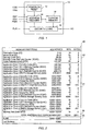
- FIG. 1 A block diagram of the generalized architecture of a secured memory 10 according to the present invention is illustrated in FIG. 1.
- the secured memory 10 there are blocks for a power on reset 12, address decoder 14, security logic 16. and an EEPROM memory 18.
- the secured memory 10 has eight pins, namely, VDD, VSS, RST, CLK, PGM, FUS, and I/O connected to the various blocks in the secured memory 10 as shown.
- the EEPROM memory 18 is partitioned, and authorized access to the various partitions to perform the operations of READ, WRITE, COMPARE, and ERASE is controlled by the security provided according to the present invention.
- the first instance arises because of the transmittal of the secured memory 10 from the manufacturer of the secured memory 10 to the issuer of the secured memory 10.
- a security code determined by the manufacturer and conveyed to the issuer must be used by the issuer to gain access to the secured memory.
- security is provided to prevent unauthorized use by one other than the end user, and to prevent anyone other than the issuer to tamper with or use the memory in a manner not permitted by the issuer.
- FIG. 2 a memory map 20 indicating the various memory partitions made to the EEPROM memory 18 is set forth.
- memory map 20 the address in the EEPROM memory 18 of each memory partition is identified along with the number of bits for each of the memory partitions.
- the partition labelled Fabrication Zone is found at addresses 0 through 15 in the memory map 20 and is allocated 16 bits.
- the bits in the EEPROM memory 18 arc grouped together as 8-bit words.
- the memory map 20 of the EEPROM memory 18 has been divided into four sections 22, 24, 26, and 28 for a more ready understanding of each of the memory partitions.
- Section 22 of memory map 20 contains partitions for the manufacturer and the issuer.
- the partitions in section 22 are the Fabrication Zone, Issuer Zone, Security Code, Security Code Attempts Counter, and Code Protected Zone.
- the Code Protected Zone is also accessible to the end user.
- the Fabrication Zone and Issuer Zone each contain information that is pertinent to the manufacturer and the issuer, respectively.
- the Fabrication Zone is programmed by the secured memory manufacturer, and is not alterable. Access to the Issuer Zone is controlled by a security code flag which is set when a valid security code is recognized by the secured memory 10.
- the partition for the Security Code contains the security code which must be matched by the issuer to access the EEPROM memory 18 and to thereby personalize various partitions in the EEPROM memory 18.
- the security code acts to secure transportation between the manufacturer and the issuer, and as will be explained more fully below, after the EEPROM memory 18 is personalized by the issuer, the security code prevents unauthorized access to the application zones of the EEPROM memory 10. As such, the security code is a global access control for the entire EEPROM memory 18.
- the Security Code Attempts Counter tallies the number of attempts made at presenting a security code.
- the secured memory 10 is locked if the Security Code Attempts Counter records eight non-valid presentations of a security code.
- the Code Protected Zone is a partition that can be used as a scratch pad wherein READ access is permitted, and WRITE/ERASE operations are controlled by the security code flag.
- Section 24 of memory map 20 contains four application zones, that include partitions for both security and memory storage.
- Each of the four application zones illustrated in memory map 20 includes a partition for a Security Code, a Security Code Attempts Counter, an Erase Key, an Erase Key Attempts Counter partition, and a Storage Memory Zone.
- the partitions for the Security Code and Security Code Attempts Counter in each of the application zones control read and write access in combination with other security measures, to their associated Storage Memory Zone
- the partitions for the Erase Key and Erase Key Attempts Counter in each of the application zones control erase access, along with other security measures, to their associated Storage Memory Zone. It should be appreciated that to those of ordinary skill in the art. writing to an EEPROM is the process of placing a logic '0' in an EEPROM memory bit and erasing is the process of placing a logic '1' in an EEPROM memory bit.
- Section 26 is a Memory Test Zone is provided to test all the operations of the secured memory 10 without the need for security access.
- Section 28 is a partition for a Fuse. Once the secured memory 10 is personalized by the issuer, the Fuse partition 28 is permanently "blown" by setting it to logic '0'. It should be appreciated that the bit which is blown is a stand alone bit of EEPROM memory that is set permanently to a logic '0'.
- a security code determined by the manufacturer is conveyed by the manufacturer to the issuer.
- the issuer For the secured memory 10 to be accessed by the issuer to personalize the secured memory 10 for the user, the issuer must input the security code conveyed by the manufacturer for comparison with the security code as programmed by the manufacturer of the secured memory into the Security Code partition in section 22 of the memory map 20.
- the issuer For the issuer to gain access to the EEPROM memory 18 there must be an exact match of the security code input by the issuer with the security code programmed by the manufacturer.
- each attempted access to the secured memory 10 by inputting a security code to be compared with the security code programmed by the manufacturer is tallied by the Security Code Attempts Counter in section 22. If eight unsuccessful attempts are made to match a security code to the programmed security code, the ability to set the security flag is no longer possible. Each time an input security code is compared to the programmed security code, and a match is made, the security code attempts counter is reset to zero.
- FIG. 3 the timing diagram 30 for the successful security code comparison and a setting of the security code flag is shown.
- the operations of RESET. READ, COMPARE, WRITE and ERASE are performed.
- the timing diagrams for the RESET, READ, COMPARE, and ERASE/WRITE operations are set forth in FIGS. 4A through 4D, respectively.
- a reset signal is first provided to the RST (reset) pin of the secured memory 10.
- the address counter in the address decoder 14 is reset to zero and the first hit of the EEPROM memory 18 is available on the I/O pin after the falling edge of the reset signal.
- the address counter is incremented by a signal provided to the CLK (clock) pin while the signal provided to the PGM (program/erase) pin of the secured memory 10 is held low until the address of the security code partition is reached. This is a READ operation.
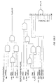
- the address counter for the EEPROM memory 18 is controlled by the address count control circuit 40 is set forth in FIG. 5.
- Two signals, CLKR and R are produced by the address count control circuit 40 to control a multi-stage counter that is used to generate the desired address of the EEPROM memory 18.
- the CLKR signal is an internal clock signal used to increment the address counter, while the R signal is an internal signal used to reset the address counter to zero.
- the address count control circuit 40 has the following input signals: PGMERASEFUNC WRT, CLK, RST, FLGRST, and CPUB.
- the PGMERASEFUNC and WRT signals are both connected to the inputs of a NOR gate 42.
- the output of the NOR gate 42 and the CLK signal are connected to the inputs of an AND gate 44.
- the output of the AND gate 44 and the RST signal are connected to the inputs of a NOR gate 46, and the output of the NOR gate 46 is passed through inverters 48 and 50 to form the CLKR signal.
- the CLK signal and the FLGRST signal are connected to the inputs of an AND gate 52.
- the output of the AND gate 52 and the CPUB signal are connected to the inputs of a NOR gate 54 having an output connected to the negative edge triggered clear input of a D-type flip-flop 56.
- the RST signal is also connected through an inverter 58 to the clock input of the D-type flip-flop 56.
- the data input of the D-type flip-flop 56 is held HIGH through an inverter 60 connected to Vss.
- the data output of the D-type flip-flop 56 and the CPUB signal are connected to the inputs of a NOR gate 62. and the output of the NOR gate 62 is passed through an inverter 64 to form the R signal.
- the PGMERASEFUNC signal is internally generated by a circuit to be described below. It is generated to suspend the address counter by not passing the CLK signal through AND gate 42 as it toggles, as can be appreciated upon inspection of the address count control circuit 40, when an erase or write cycle is being performed.
- the RST signal is generated externally to reset the address counter to zero. When the RST signal makes a transition from HIGH to LOW, D-type flip-flop 56 is clocked, and data output D-type flip-flop 56 goes HIGH. As a result, the R signal goes HIGH and the address counter is reset to zero.
- the FLGRST signal resets the R signal LOW after the address counter has been reset to zero when the R signal went HIGH.
- the FLGRST signal is generated by the address counter when the address in the EEPROM memory 18 is zero either when the EEPROM memory 18 is reset or the address counter has rolled over to zero.
- the CPUB signal is generated when the secured memory 10 is powered up.
- the output of the address counter is fed into a control word identifier that is employed to generate control word signals to indicate when particular addresses in the EEPROM memory 18 have been reached.
- the control word identifier also generates a signal for the first bit, the second bit, and the eighth (last) bit of each word in the EEPROM memory 18.
- the signals generated by the control word identifier are used by the security logic to identify which partition in the EEPROM memory 18 is being accessed, as well as whether the first, second, or last bits of a word are also being addressed.
- a bit by bit comparison of the programmed security code to the security code presented to the I/O pin is then made as the clock signal increments the address of the programmed security code.
- the comparison is made by the compare bit circuit 70 illustrated in FIG. 6.
- data read out from the EEPROM 18 a bit at a time by a sense amplifier on the SAOUT line is compared by XNOR gate 72 with the security code being input on the I/O line as it is clocked through the D-type flip-flop 74.
- the address counter is incremented on the falling edge of the clock, and the input data is latched on the rising edge of the clock. The comparison is done on the next falling edge of the clock.
- a comparison is made at the time D-type flip-flop 82 is clocked. As the comparison is made, the CMPBIT must remain HIGH for the comparison to indicate a match. For the CMPBIT to be HIGH, both of the inputs to NAND gate 80, must be HIGH, if one of the inputs goes LOW, then the CMPBIT signal will stay LOW. Since, one of the inputs to NAND gate 80 is connected to the output of OR gate 78, the output of OR gate 78 must remain HIGH for the CMPBIT signal to remain HIGH.
- the inputs to OR gate 78 are the output of the comparison from XNOR gate 72 and the SC WORD signal fed through inverter 76.
- a validation operation After a match of the programmed security code to the input security code, a validation operation must be performed. In the validation operation, the Security Code Attcmpts Counter is incremented and a READ operation is performed until a logic '1' is found in the Security Code Attempts Counter. During a READ operation, the address counter is incremented. In the READ operation, when the address counter is incremented, the first bit is available on the I/O after the falling edge of the clock. It should be appreciated that a Security Code Attempts Counter that has all logic '1's indicates that no unsuccessful attempted matches have been made since the Security Code Attempts counter was reset. At the address in which the logic '1' is found, a WRITE operation is then performed to place a logic '0' at that address location.
- the write zero verification circuit 90 is illustrated in FIG. 7.
- the input signals to the write zero verification circuit 90 are CPUB, CLK, PGM, and SAOUT.
- the CPUB signal is connected through an inverter 92 to an input of an AND gate 94 and the clear input 'C' of D-type flip-flop 100.
- the CLK signal is connected to the input of a first NAND gate 96, a second NAND gate 98, the clock input of a D-type flip-flop 100, and a third NAND gate 102.
- the PGM signal is connected to the clock input of a D-type flip-flop 104, and through an inverter 106 to the data input of D-type flip-flop 100 and to an input of third NAND gate 102.
- the data output of D-type flip-flop 100 is also connected to an input of third NAND gate 102.
- the output of third NAND gate 102 is connected to an input of AND gate 94.
- the SAOUT signal is connected to the data input of the D-type flip-flop 104.
- Another input of first NAND gate 96 is connected to the data output of D-type flip-flop 104 through an inverter 108.
- the output of first NAND gate 96 is connected to one input of an AND gate 110, while the other input of AND gate 110 is connected to the output of AND gate 94.
- the output of AND gate 94 is also connected to the negative edge triggered clear input'C' of D-type flip-flop 112, and an input of NAND gate 98.
- D-type flip-flop 104 The data output of D-type flip-flop 104 is also connected to NAND gate 98. and the inverted output of D-type flip-flop 104 is connected to the clock input of D-type flip-flop 112. Vss is connected to the data input of D-type flip-flop 112 through an inverter 114, and the data output of D-type flip-flop 112 forms the output of write zero verification circuit 90 after passing through inverters 116 and 118.
- the SAOUT signal should be a logic '1'.
- the PGM signal goes HIGH to start a WRITE '0' to the address in the security code attempts counter from which the logic'1' was read, a logic '1' should be latched at the 'Q' output of D-type flip-flop 104.
- the WROVEN signal is LOW. If a WRITE '0' occurred, the SAOUT signal will be latched on the next rising edge of PGM.
- An ERASE operation is then performed on the Security Code Attempts Counter. This will result in a logic '1' being latched at the output of D-type flip-flop 112 on the rising edge of the clock input of D-type flip-flop 112. It should be appreciated that when a WRITE operation is performed only a single bit is changed, but when an ERASE operation is performed the whole byte is changed. A READ operation is then performed to indicate that the security code flag has been set because an erasure of the Security Code Attempts Counter has been permitted. A READ out of a logic '1' indicates that the security code flag has been set because an erasure of the Security Code Attempts Counter has occurred.
- a READ out of a logic '0' indicates that the security code flag has not been set because no erasure of the Security Code Attempts Counter has occurred.
- D-type flip-flop 100, NAND gate 102 and AND gate 94 ensure that the WR0VEN signal will be forced to a logic '0' if the power is reset or the address is incremented.
- the security code flag will be set by the security flag circuit 120 illustrated in FIG. 8.
- the inputs to the security code flag circuit 120 are ENABLE, CPUB, WR0VEN, ACWORD, and CMPBIT, and the output is SV.
- the ENABLE signal is connected through an inverter 122 to an input of a NOR gate 124, and also to an input of a NAND gate 126. Connected to two other inputs of NAND gate 126 are the signals ACWORD and CMPBIT.
- the CPUB signal is connected to another input of NOR gate 124, and the output of NOR gate 124 is connected to the negative edge triggered clear input 'C' of a D-type flip-flop 128.
- WR0VEN signal is connected to the clock input of D-type flip-flop 128.
- the data input of D-type flip-flop 128 is connected to the output of a NAND gate 130 having a first input connected to the output of NAND gate 126 and a second input connected to the data output of D-type flip-flop 128 through an inverter 132.
- D-type flip-flop 128 will latch a HIGH output SV (Given that ENABLE and AC WORD are also HIGH) SV will remain HIGH as long as power is supplied to the secured memory 10 and ENABLE is HIGH, since the logic '1' on SV feed s though an inverter to NAND gate 130 to input a logic '0' to the NAND gate 130. The input to D-type flip-flop 128 will remain HIGH due to this feedhack.
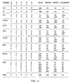
- the issuer of the secured memory 10 has access to personalize the application zones for the end user. After personalizing the desired portions of the secured memory 10 to which the issuer has access, the value in the Fuse in section 28 is written to a logic '0'. Set forth in table 1 in FIG. 9 are the access conditions for personalizing the secured memory 10 prior to the Fuse being set to logic '0'. To personalize the secured memory 10, the issuer writes or erases the desired data into the secured memory 10 as permitted by the access conditions.
- the code SV represents the security code flag which when set is a logic '1'
- 'X' indicates a don't care.
- SAC Security Code Attempts Counter
- the Rn flag is set by the value in the second bit in each of the four Storage Memory Zones. The Rn flag will remain set until the power of the secured memory is disabled even though the second bit in the particular Storage Memory Zone may be written to a logic '0' by a subsequent operation.
- the P and R flag set circuit 140 which sets the Rn flag.
- the P and R flag set circuit 140 also sets a Pn flag to he described below.
- the P and R flag set circuit 140 has input signals CPUB, CLKB, BIT0, SAOUT, WORD, and BIT1.
- the CPUB signal is connected to a reset input 'R' of D-type flip flops 142 and 144.
- the CLKB signal is connected to the clock input or D-type flip flops 142 and 144.
- the SAOUT and WORD signals are connected to the first and second inputs of AND gates 146 and 148, and the BIT0 and BIT1 signals are connected to first inputs of AND gates 146 and 148, respectively.
- the outputs of AND gates 146 and 148 are connected to a first input of NOR gates 150 and 152, respectively.
- the outputs of NOR gates 150 and 152 are connected to the data inputs of D-type flip-flops 142 and 144, respectively.
- the data outputs of D-type flip-flops 142 and 144 are fed back to second inputs of NOR gates 150 and 152, respectively, and also form the Pn and Rn flags.
- the BIT0, BIT1, and WORD signals are set by the control word identifier circuit.
- the address is at the partition in the memory from which the Rn flag is to be read, the WORD signal and BIT1 of that word will be HIGH, and if the value at BIT1 read out on the SAOUT line is also HIGH the RN flag will be set.
- the Rn flag will remain set until the power of the secured memory is disabled by the CPUB signal.
- FIG. 9 which flags must be set to read, write, erase or compare data in the partitions of the secured memory 10. Reading, writing, erasing, and comparing data in the secured memory 10 is accomplished by applying the appropriate sequence of signals to the pins of the secured memory 10 as taught by the timing diagrams in FIGS. 4A through 4D.
- the address of the EEPROM memory 10 is first reset to zero by performing a RESET operation.
- RESET operation may be performed by applying signals to the pins of the secured memory in the order dictated by the timing diagram for the RESET operation set forth in FIG. 4A.
- a READ operation is then performed until the address in the address counter is incremented to the initial address to the partition for the Security Code in the first application zone.
- a WRITE operation is performed to write the desired data to the address of the Security Code in the first application zone.
- the Fuse partition is permanently set to logic '0' to emulate the state of a blown fuse.
- the Sn code is a logic '1'.
- a secure code which matches the security code stored in the Secure Code partition of the particular application zone must be presented.
- the compare and validation operations are performed in the same manner discussed above for the security code found in the Secure Code partition of section 22. The only difference is that the comparison will understandably begin at the address of the Secure Code partition associated with the selected application zone.
- the code Pn is a write flag for each of the four application zones.
- the Pn flag is set by the value in the first bit in each of the four Application Zones.
- the Pn flag when set is a logic '1'.
- the Pn flag will remain set until the power of the secured memory is disabled even though the first bit in the particular Application Zone may be written to a logic '0' by a subsequent operation.
- the setting of the Pn flag is accomplished as described with respect to FIG. 10.
- the code En represents an erase code flag for the four Application Zones.
- the En code is a logic '1'.
- an erase code which matches the erase code stored in the Erase Key partition of the particular application zone must be presented.
- the compare and validation operations are performed in the same manner discussed above for the security code found in the Secure Code partition of section 22. The only difference is that the comparison will understandably begin at the address of the Erase Key partition associated with the selected application zone.
- the correct combinations of the SV, Sn, Pn, Rn, and En flags must be set.
- the required combinations of the SV, Sn, Pn, Rn, and En flags that must be set to read, write, erase, and compare in one of the Storage Memory Zones will be discussed.
- the access provided by different combinations of flags may be readily understood by dividing the different combinations of flags into three groups.
- FIGS. 12A-12C The circuit diagram of the combinatorial logic for generating the enable signals sent to the EEPROM 18 so that a READ, WRITE, or ERASE, of the data in the EEPROM 18 can be made, and the enable signals for blowing the fuses for personalization as described above is illustrated in FIGS. 12A-12C.
- FIGS. 12A -12C One of ordinary skill in the art will readily recognize from FIGS. 12A -12C that the flags must be set as previously described to obtain the desired output enable signals from FIGS. 12A-12C.
- FIG. 12A generates a read enable signal which is HIGH when the PGMERASEFUNC is LOW, the MEM signal is HIGH, and flags for a selected partition being accessed is also HIGH. To avoid overcomplicating the disclosure, each of these flags which have been described above will not be described again herein.
- FIGS. 12B and 12C generate write control (WRT GTRL), fuse write control (FZ WRT CTRL), and clear or erase control (CLR CTRL), respectively, from flags set as described above.
- the WRT CTRL, FZ WRT CTRL, and CLR CTRL signals are then fed into a write and erase control circuit illustrated in FIG. 13 that generates the signals WRTEN, CLREN, and WRT employed by the EEPROM 18 to write and erase data, and also generates the enable signal for controlling the programming signal for the fuses, FZ WRT EN.
- FIGS. 12A- 12C, and 13 will readily appreciate the operation of the circuits set forth in FIGS. 12A- 12C, and 13 to generate the enable signals for read, write, erase, and fuse programming according to the flags described above.
Landscapes
- Engineering & Computer Science (AREA)
- Theoretical Computer Science (AREA)
- General Physics & Mathematics (AREA)
- Physics & Mathematics (AREA)
- Business, Economics & Management (AREA)
- Microelectronics & Electronic Packaging (AREA)
- Computer Networks & Wireless Communication (AREA)
- Accounting & Taxation (AREA)
- Strategic Management (AREA)
- General Business, Economics & Management (AREA)
- General Engineering & Computer Science (AREA)
- Computer Security & Cryptography (AREA)
- Quality & Reliability (AREA)
- Storage Device Security (AREA)
- Credit Cards Or The Like (AREA)
- Inorganic Insulating Materials (AREA)
- Cold Air Circulating Systems And Constructional Details In Refrigerators (AREA)
- Warehouses Or Storage Devices (AREA)
Applications Claiming Priority (3)
| Application Number | Priority Date | Filing Date | Title |
|---|---|---|---|
| US08/943,510 US5991519A (en) | 1997-10-03 | 1997-10-03 | Secure memory having multiple security levels |
| US943510 | 1997-10-03 | ||
| PCT/US1998/019944 WO1999018504A1 (en) | 1997-10-03 | 1998-09-23 | Secure memory having multiple security levels |
Publications (3)
| Publication Number | Publication Date |
|---|---|
| EP1019817A1 EP1019817A1 (en) | 2000-07-19 |
| EP1019817A4 EP1019817A4 (en) | 2001-01-03 |
| EP1019817B1 true EP1019817B1 (en) | 2003-02-05 |
Family
ID=25479792
Family Applications (1)
| Application Number | Title | Priority Date | Filing Date |
|---|---|---|---|
| EP98948495A Expired - Lifetime EP1019817B1 (en) | 1997-10-03 | 1998-09-23 | Secure memory having multiple security levels |
Country Status (12)
| Country | Link |
|---|---|
| US (1) | US5991519A (ko) |
| EP (1) | EP1019817B1 (ko) |
| JP (1) | JP2001519561A (ko) |
| KR (1) | KR100544243B1 (ko) |
| CN (1) | CN1218249C (ko) |
| AU (1) | AU9505698A (ko) |
| CA (1) | CA2303348A1 (ko) |
| DE (1) | DE69811254T2 (ko) |
| HK (1) | HK1031001A1 (ko) |
| NO (1) | NO319811B1 (ko) |
| RU (1) | RU2214008C2 (ko) |
| WO (1) | WO1999018504A1 (ko) |
Cited By (1)
| Publication number | Priority date | Publication date | Assignee | Title |
|---|---|---|---|---|
| EP1467312A1 (en) | 2003-04-09 | 2004-10-13 | Sony Corporation | Data communication apparatus and method for managing memory in the same |
Families Citing this family (50)
| Publication number | Priority date | Publication date | Assignee | Title |
|---|---|---|---|---|
| US10361802B1 (en) | 1999-02-01 | 2019-07-23 | Blanding Hovenweep, Llc | Adaptive pattern recognition based control system and method |
| US6012049A (en) * | 1998-02-04 | 2000-01-04 | Citicorp Development Center, Inc. | System for performing financial transactions using a smartcard |
| EP1113387A3 (en) * | 1999-12-31 | 2001-11-21 | SCHLUMBERGER Systèmes | Smart card having a non-volatile memory with a novel mapping |
| IL149052A0 (en) * | 2000-02-21 | 2002-11-10 | Trek Technology Singapore Pte | A portable data storage device |
| US7350204B2 (en) * | 2000-07-24 | 2008-03-25 | Microsoft Corporation | Policies for secure software execution |
| US7702785B2 (en) * | 2001-01-31 | 2010-04-20 | International Business Machines Corporation | Methods, systems and computer program products for selectively allowing users of a multi-user system access to network resources |
| US7181017B1 (en) | 2001-03-23 | 2007-02-20 | David Felsher | System and method for secure three-party communications |
| CA2350029A1 (en) * | 2001-06-08 | 2002-12-08 | Cloakware Corporation | Sustainable digital watermarking via tamper-resistant software |
| GB2376540B (en) * | 2001-06-12 | 2005-05-04 | Hewlett Packard Co | Upgrade of licensed capacity on computer entity |
| US7243853B1 (en) | 2001-12-04 | 2007-07-17 | Visa U.S.A. Inc. | Method and system for facilitating memory and application management on a secured token |
| DE10162307A1 (de) * | 2001-12-19 | 2003-07-03 | Philips Intellectual Property | Verfahren und Anordnung zur Herstellung von maskenprogrammierten ROMs unter Verwendung einer mehrere Systeme umfassenden Maske sowie ein entsprechendes Computerprogrammprodukt und ein entsprechendes computerlesbares Speichermedium |
| DE10218795B4 (de) * | 2002-04-22 | 2009-03-19 | Deutscher Sparkassen Verlag Gmbh | Verfahren zum Herstellen eines elektronischen Sicherheitsmoduls |
| JP3979195B2 (ja) * | 2002-06-25 | 2007-09-19 | ソニー株式会社 | 情報記憶装置、およびメモリアクセス制御方法、並びにコンピュータ・プログラム |
| US7444682B2 (en) * | 2002-07-03 | 2008-10-28 | Macronix International Co., Ltd. | Security memory device and method for making same |
| US7395435B2 (en) * | 2002-09-20 | 2008-07-01 | Atmel Corporation | Secure memory device for smart cards |
| US20040139021A1 (en) | 2002-10-07 | 2004-07-15 | Visa International Service Association | Method and system for facilitating data access and management on a secure token |
| US20040128528A1 (en) * | 2002-12-31 | 2004-07-01 | Poisner David I. | Trusted real time clock |
| US9818136B1 (en) | 2003-02-05 | 2017-11-14 | Steven M. Hoffberg | System and method for determining contingent relevance |
| US20050005105A1 (en) * | 2003-06-24 | 2005-01-06 | Brown Larry Cecil | Remote access control feature for limiting access to configuration file components |
| US20050257016A1 (en) * | 2004-05-17 | 2005-11-17 | Brian Boles | Digital signal controller secure memory partitioning |
| JP4717381B2 (ja) | 2004-06-11 | 2011-07-06 | 株式会社エヌ・ティ・ティ・ドコモ | 移動機、及び、アクセス制御方法 |
| US8447975B2 (en) * | 2005-07-07 | 2013-05-21 | International Business Machines Corporation | Workstation application server programming protection via classloader policy based visibility control |
| US20070011723A1 (en) * | 2005-07-07 | 2007-01-11 | Ching-Yun Chao | Method for maintaining application compatibility within an application isolation policy |
| US7395964B2 (en) * | 2005-09-06 | 2008-07-08 | International Business Machines Corporation | Secure voting system |
| JP4361894B2 (ja) | 2005-09-15 | 2009-11-11 | 株式会社エヌ・ティ・ティ・ドコモ | 外部メモリ管理装置、及び外部メモリ管理方法 |
| US8874477B2 (en) | 2005-10-04 | 2014-10-28 | Steven Mark Hoffberg | Multifactorial optimization system and method |
| KR100652017B1 (ko) * | 2005-12-08 | 2006-12-01 | 한국전자통신연구원 | 물리보안공격에 대한 닥시스 케이블 모뎀의 보안 방법 |
| US8997255B2 (en) | 2006-07-31 | 2015-03-31 | Inside Secure | Verifying data integrity in a data storage device |
| US8301890B2 (en) * | 2006-08-10 | 2012-10-30 | Inside Secure | Software execution randomization |
| US7613907B2 (en) * | 2006-08-11 | 2009-11-03 | Atmel Corporation | Embedded software camouflage against code reverse engineering |
| US7984301B2 (en) * | 2006-08-17 | 2011-07-19 | Inside Contactless S.A. | Bi-processor architecture for secure systems |
| US8352752B2 (en) * | 2006-09-01 | 2013-01-08 | Inside Secure | Detecting radiation-based attacks |
| US7554865B2 (en) * | 2006-09-21 | 2009-06-30 | Atmel Corporation | Randomizing current consumption in memory devices |
| US7882365B2 (en) * | 2006-12-22 | 2011-02-01 | Spansion Llc | Systems and methods for distinguishing between actual data and erased/blank memory with regard to encrypted data |
| US9137203B2 (en) * | 2007-01-24 | 2015-09-15 | International Business Machines Corporation | Centralized secure offload of cryptographic security services for distributed security enforcement points |
| US8423789B1 (en) | 2007-05-22 | 2013-04-16 | Marvell International Ltd. | Key generation techniques |
| US8392983B2 (en) * | 2007-07-31 | 2013-03-05 | Viasat, Inc. | Trusted labeler |
| US8510560B1 (en) | 2008-08-20 | 2013-08-13 | Marvell International Ltd. | Efficient key establishment for wireless networks |
| KR101595043B1 (ko) | 2008-09-18 | 2016-02-17 | 마벨 월드 트레이드 리미티드 | 적어도 부분적으로 부팅 동안에 어플리케이션들을 메모리에 프리로딩하는 방법 |
| US8645716B1 (en) * | 2010-10-08 | 2014-02-04 | Marvell International Ltd. | Method and apparatus for overwriting an encryption key of a media drive |
| US9436629B2 (en) | 2011-11-15 | 2016-09-06 | Marvell World Trade Ltd. | Dynamic boot image streaming |
| US9575768B1 (en) | 2013-01-08 | 2017-02-21 | Marvell International Ltd. | Loading boot code from multiple memories |
| US9736801B1 (en) | 2013-05-20 | 2017-08-15 | Marvell International Ltd. | Methods and apparatus for synchronizing devices in a wireless data communication system |
| US9521635B1 (en) | 2013-05-21 | 2016-12-13 | Marvell International Ltd. | Methods and apparatus for selecting a device to perform shared functionality in a deterministic and fair manner in a wireless data communication system |
| EP3028145A1 (en) | 2013-07-31 | 2016-06-08 | Marvell World Trade Ltd. | Parallelizing boot operations |
| US11809610B2 (en) * | 2014-06-16 | 2023-11-07 | Texas Instruments Incorporated | Hardware protection of inline cryptographic processor |
| DE102015223335A1 (de) * | 2015-11-25 | 2017-06-01 | Robert Bosch Gmbh | Verfahren zum Betreiben eines Mikrocontrollers |
| US20170262180A1 (en) * | 2016-03-08 | 2017-09-14 | Burlywood, LLC | Integrated control of write-once data storage devices |
| CN109075968A (zh) | 2016-03-08 | 2018-12-21 | 马维尔国际贸易有限公司 | 用于安全设备认证的方法和装置 |
| US11050569B2 (en) * | 2019-08-14 | 2021-06-29 | Macronix International Co., Ltd. | Security memory scheme |
Family Cites Families (8)
| Publication number | Priority date | Publication date | Assignee | Title |
|---|---|---|---|---|
| DE3318083A1 (de) * | 1983-05-18 | 1984-11-22 | Siemens AG, 1000 Berlin und 8000 München | Schaltungsanordnung mit einem speicher und einer zugriffskontrolleinheit |
| JPH0734215B2 (ja) * | 1985-02-27 | 1995-04-12 | 株式会社日立製作所 | Icカ−ド |
| FR2626095B1 (fr) * | 1988-01-20 | 1991-08-30 | Sgs Thomson Microelectronics | Systeme de securite pour proteger des zones de programmation d'une carte a puce |
| FR2673476B1 (fr) * | 1991-01-18 | 1996-04-12 | Gemplus Card Int | Procede securise de chargement de plusieurs applications dans une carte a memoire a microprocesseur. |
| US5508691A (en) * | 1992-06-22 | 1996-04-16 | Lynx Systems, Inc. | Self-contained electronic lock with changeable master and slave codes |
| IL111151A (en) * | 1994-10-03 | 1998-09-24 | News Datacom Ltd | Secure access systems |
| US5606315A (en) * | 1994-12-12 | 1997-02-25 | Delco Electronics Corp. | Security method for protecting electronically stored data |
| US5699514A (en) * | 1995-12-26 | 1997-12-16 | Lucent Technologies Inc. | Access control system with lockout |
-
1997
- 1997-10-03 US US08/943,510 patent/US5991519A/en not_active Expired - Lifetime
-
1998
- 1998-09-23 KR KR1020007003576A patent/KR100544243B1/ko not_active IP Right Cessation
- 1998-09-23 WO PCT/US1998/019944 patent/WO1999018504A1/en active IP Right Grant
- 1998-09-23 EP EP98948495A patent/EP1019817B1/en not_active Expired - Lifetime
- 1998-09-23 JP JP2000515226A patent/JP2001519561A/ja not_active Withdrawn
- 1998-09-23 CA CA002303348A patent/CA2303348A1/en not_active Abandoned
- 1998-09-23 DE DE69811254T patent/DE69811254T2/de not_active Expired - Lifetime
- 1998-09-23 RU RU2000111507/09A patent/RU2214008C2/ru not_active IP Right Cessation
- 1998-09-23 CN CN988098423A patent/CN1218249C/zh not_active Expired - Fee Related
- 1998-09-23 AU AU95056/98A patent/AU9505698A/en not_active Abandoned
-
2000
- 2000-03-30 NO NO20001665A patent/NO319811B1/no unknown
-
2001
- 2001-03-08 HK HK01101682A patent/HK1031001A1/xx not_active IP Right Cessation
Cited By (1)
| Publication number | Priority date | Publication date | Assignee | Title |
|---|---|---|---|---|
| EP1467312A1 (en) | 2003-04-09 | 2004-10-13 | Sony Corporation | Data communication apparatus and method for managing memory in the same |
Also Published As
| Publication number | Publication date |
|---|---|
| AU9505698A (en) | 1999-04-27 |
| US5991519A (en) | 1999-11-23 |
| CN1276891A (zh) | 2000-12-13 |
| NO20001665D0 (no) | 2000-03-30 |
| CN1218249C (zh) | 2005-09-07 |
| KR20010030883A (ko) | 2001-04-16 |
| RU2214008C2 (ru) | 2003-10-10 |
| NO319811B1 (no) | 2005-09-19 |
| JP2001519561A (ja) | 2001-10-23 |
| HK1031001A1 (en) | 2001-05-25 |
| WO1999018504A1 (en) | 1999-04-15 |
| EP1019817A1 (en) | 2000-07-19 |
| CA2303348A1 (en) | 1999-04-15 |
| NO20001665L (no) | 2000-03-30 |
| DE69811254T2 (de) | 2003-09-25 |
| KR100544243B1 (ko) | 2006-01-23 |
| DE69811254D1 (de) | 2003-03-13 |
| EP1019817A4 (en) | 2001-01-03 |
Similar Documents
| Publication | Publication Date | Title |
|---|---|---|
| EP1019817B1 (en) | Secure memory having multiple security levels | |
| US6094724A (en) | Secure memory having anti-wire tapping | |
| US4102493A (en) | Systems for storing and transferring data | |
| US4442345A (en) | Apparatus for and method of recycling recording carriers, such as credit cards, including non-volatile erasable memories for identification data | |
| US5504701A (en) | Memory card | |
| US5101121A (en) | Security locks for integrated circuit | |
| JPH0682405B2 (ja) | テストプログラム起動方式 | |
| JPH06208515A (ja) | メモリー・カード | |
| US5442165A (en) | Secure IC card system with reusable prototype IC card | |
| JPS62190584A (ja) | 携帯可能電子装置 | |
| US5978915A (en) | Device for the protection of the access to memory words | |
| EP3091468B1 (en) | Integrated circuit access | |
| JP2005524915A (ja) | システムおよび認証方法 | |
| US6212105B1 (en) | Method for recording a binary word by means of electrically erasable and programmable type memory cells | |
| US7436702B2 (en) | Integrated circuit with a data memory protected against UV erasure | |
| US20060282683A1 (en) | Flash array read, erase, and program security | |
| JPH07105335A (ja) | 情報カード | |
| JPH09231329A (ja) | メモリカード | |
| JP2000259801A (ja) | 初期化機能付きicカード用メモリ装置 | |
| JPH02259893A (ja) | 携帯型半導体記憶装置 | |
| JPH04367045A (ja) | 半導体記憶装置 | |
| JPH07105336A (ja) | 情報カード | |
| JPH01177184A (ja) | 携帯可能電子装置 | |
| JPH07105334A (ja) | 情報カード | |
| JPS63123182A (ja) | デ−タ書込み方式 |
Legal Events
| Date | Code | Title | Description |
|---|---|---|---|
| PUAI | Public reference made under article 153(3) epc to a published international application that has entered the european phase |
Free format text: ORIGINAL CODE: 0009012 |
|
| 17P | Request for examination filed |
Effective date: 20000503 |
|
| AK | Designated contracting states |
Kind code of ref document: A1 Designated state(s): DE FI FR GB IT NL SE |
|
| A4 | Supplementary search report drawn up and despatched |
Effective date: 20001122 |
|
| AK | Designated contracting states |
Kind code of ref document: A4 Designated state(s): DE FI FR GB IT NL SE |
|
| RIC1 | Information provided on ipc code assigned before grant |
Free format text: 7G 06F 11/00 A, 7G 06F 7/04 B, 7G 07D 7/00 B, 7G 07F 7/10 B, 7G 06F 12/14 B, 7G 06F 1/00 B |
|
| 17Q | First examination report despatched |
Effective date: 20020506 |
|
| GRAH | Despatch of communication of intention to grant a patent |
Free format text: ORIGINAL CODE: EPIDOS IGRA |
|
| GRAH | Despatch of communication of intention to grant a patent |
Free format text: ORIGINAL CODE: EPIDOS IGRA |
|
| GRAA | (expected) grant |
Free format text: ORIGINAL CODE: 0009210 |
|
| AK | Designated contracting states |
Designated state(s): DE FI FR GB IT NL SE |
|
| REG | Reference to a national code |
Ref country code: GB Ref legal event code: FG4D |
|
| REF | Corresponds to: |
Ref document number: 69811254 Country of ref document: DE Date of ref document: 20030313 Kind code of ref document: P |
|
| REG | Reference to a national code |
Ref country code: SE Ref legal event code: TRGR |
|
| ET | Fr: translation filed | ||
| PLBE | No opposition filed within time limit |
Free format text: ORIGINAL CODE: 0009261 |
|
| STAA | Information on the status of an ep patent application or granted ep patent |
Free format text: STATUS: NO OPPOSITION FILED WITHIN TIME LIMIT |
|
| 26N | No opposition filed |
Effective date: 20031106 |
|
| PGFP | Annual fee paid to national office [announced via postgrant information from national office to epo] |
Ref country code: NL Payment date: 20050916 Year of fee payment: 8 |
|
| PGFP | Annual fee paid to national office [announced via postgrant information from national office to epo] |
Ref country code: SE Payment date: 20050921 Year of fee payment: 8 |
|
| PGFP | Annual fee paid to national office [announced via postgrant information from national office to epo] |
Ref country code: FI Payment date: 20050922 Year of fee payment: 8 |
|
| PG25 | Lapsed in a contracting state [announced via postgrant information from national office to epo] |
Ref country code: FI Free format text: LAPSE BECAUSE OF NON-PAYMENT OF DUE FEES Effective date: 20060923 |
|
| PG25 | Lapsed in a contracting state [announced via postgrant information from national office to epo] |
Ref country code: SE Free format text: LAPSE BECAUSE OF NON-PAYMENT OF DUE FEES Effective date: 20060924 |
|
| PG25 | Lapsed in a contracting state [announced via postgrant information from national office to epo] |
Ref country code: NL Free format text: LAPSE BECAUSE OF NON-PAYMENT OF DUE FEES Effective date: 20070401 |
|
| EUG | Se: european patent has lapsed | ||
| NLV4 | Nl: lapsed or anulled due to non-payment of the annual fee |
Effective date: 20070401 |
|
| PGFP | Annual fee paid to national office [announced via postgrant information from national office to epo] |
Ref country code: IT Payment date: 20080926 Year of fee payment: 11 |
|
| PGFP | Annual fee paid to national office [announced via postgrant information from national office to epo] |
Ref country code: GB Payment date: 20090929 Year of fee payment: 12 |
|
| PG25 | Lapsed in a contracting state [announced via postgrant information from national office to epo] |
Ref country code: IT Free format text: LAPSE BECAUSE OF NON-PAYMENT OF DUE FEES Effective date: 20090923 |
|
| GBPC | Gb: european patent ceased through non-payment of renewal fee |
Effective date: 20100923 |
|
| REG | Reference to a national code |
Ref country code: FR Ref legal event code: ST Effective date: 20110531 |
|
| PG25 | Lapsed in a contracting state [announced via postgrant information from national office to epo] |
Ref country code: FR Free format text: LAPSE BECAUSE OF NON-PAYMENT OF DUE FEES Effective date: 20100930 |
|
| PG25 | Lapsed in a contracting state [announced via postgrant information from national office to epo] |
Ref country code: GB Free format text: LAPSE BECAUSE OF NON-PAYMENT OF DUE FEES Effective date: 20100923 |
|
| PGFP | Annual fee paid to national office [announced via postgrant information from national office to epo] |
Ref country code: FR Payment date: 20091006 Year of fee payment: 12 |
|
| PGFP | Annual fee paid to national office [announced via postgrant information from national office to epo] |
Ref country code: DE Payment date: 20120927 Year of fee payment: 15 |
|
| REG | Reference to a national code |
Ref country code: DE Ref legal event code: R082 Ref document number: 69811254 Country of ref document: DE Representative=s name: GRUENECKER, KINKELDEY, STOCKMAIR & SCHWANHAEUS, DE |
|
| REG | Reference to a national code |
Ref country code: DE Ref legal event code: R119 Ref document number: 69811254 Country of ref document: DE Effective date: 20140401 |
|
| PG25 | Lapsed in a contracting state [announced via postgrant information from national office to epo] |
Ref country code: DE Free format text: LAPSE BECAUSE OF NON-PAYMENT OF DUE FEES Effective date: 20140401 |