EP1017942B1 - Regulating device for an adjustable hydraulic pump with several consumers - Google Patents
Regulating device for an adjustable hydraulic pump with several consumers Download PDFInfo
- Publication number
- EP1017942B1 EP1017942B1 EP98951462A EP98951462A EP1017942B1 EP 1017942 B1 EP1017942 B1 EP 1017942B1 EP 98951462 A EP98951462 A EP 98951462A EP 98951462 A EP98951462 A EP 98951462A EP 1017942 B1 EP1017942 B1 EP 1017942B1
- Authority
- EP
- European Patent Office
- Prior art keywords
- control
- pressure
- line
- output
- delivery
- Prior art date
- Legal status (The legal status is an assumption and is not a legal conclusion. Google has not performed a legal analysis and makes no representation as to the accuracy of the status listed.)
- Expired - Lifetime
Links
- 230000001105 regulatory effect Effects 0.000 title claims abstract description 29
- 238000011144 upstream manufacturing Methods 0.000 claims abstract description 8
- 238000010276 construction Methods 0.000 claims description 9
- 238000005259 measurement Methods 0.000 abstract 1
- 238000006073 displacement reaction Methods 0.000 description 2
- 230000001419 dependent effect Effects 0.000 description 1
- 238000011161 development Methods 0.000 description 1
- 230000018109 developmental process Effects 0.000 description 1
- 238000009499 grossing Methods 0.000 description 1
- 238000004519 manufacturing process Methods 0.000 description 1
- 238000012986 modification Methods 0.000 description 1
- 230000004048 modification Effects 0.000 description 1
- 230000003252 repetitive effect Effects 0.000 description 1
- 230000000284 resting effect Effects 0.000 description 1
Images
Classifications
-
- F—MECHANICAL ENGINEERING; LIGHTING; HEATING; WEAPONS; BLASTING
- F04—POSITIVE - DISPLACEMENT MACHINES FOR LIQUIDS; PUMPS FOR LIQUIDS OR ELASTIC FLUIDS
- F04B—POSITIVE-DISPLACEMENT MACHINES FOR LIQUIDS; PUMPS
- F04B49/00—Control, e.g. of pump delivery, or pump pressure of, or safety measures for, machines, pumps, or pumping installations, not otherwise provided for, or of interest apart from, groups F04B1/00 - F04B47/00
- F04B49/08—Regulating by delivery pressure
-
- F—MECHANICAL ENGINEERING; LIGHTING; HEATING; WEAPONS; BLASTING
- F04—POSITIVE - DISPLACEMENT MACHINES FOR LIQUIDS; PUMPS FOR LIQUIDS OR ELASTIC FLUIDS
- F04B—POSITIVE-DISPLACEMENT MACHINES FOR LIQUIDS; PUMPS
- F04B2205/00—Fluid parameters
- F04B2205/06—Pressure in a (hydraulic) circuit
- F04B2205/061—Pressure in a (hydraulic) circuit after a throttle
Definitions
- the invention relates to a control device for a hydraulic pump, in particular for Control of a construction machine, e.g. B. a backhoe loader.
- a control device is known from the DE 195 17 974 A1 known.
- a similar control device is known from DE 33 45 264 A1 out.
- an adjustable hydraulic pump delivers in a delivery line leading to a consumer.
- a flow control valve is provided that via a first control line with the delivery line downstream of the metering throttle and via a second control line with the delivery line upstream of the metering throttle connected is.
- the pressure drop occurring at the metering throttle therefore serves Control of the flow control valve, which the signal pressure for the Controls the delivery volume of the hydraulic pump acting adjustment device.
- a Power control valve which between the first control line and a Pressure medium tank is arranged.
- the capacity control valve opens in the opening direction acted upon by the control pressure in the first control line while it is in Closing direction via a measuring spring arrangement from the adjusting device in Dependence on the delivery volume predetermined by the adjusting device Hydraulic pump is applied.
- a suitable choice of the measuring spring arrangement the hyperbolic characteristic of a given maximum power at least approximate.
- the control characteristic of the control device is maximized by the Flow control valve determines which the flow of the hydraulic pump on the adjusted by the opening cross section of the metering throttle predetermined value.
- the capacity control valve speaks if the specified maximum capacity is exceeded on and limits the pressure in the first control line, so that the hydraulic pump swung back and an overload is avoided.
- the known control devices are also used to control several Suitable for consumers.
- a power control is required.
- a power control is required to to avoid overloading the drive motor for the hydraulic pump while it is other consumers, where a power limit becomes an undesirable one Lack of performance leads.
- a backhoe loader one or more hydraulic tools and a hydraulic travel drive.
- a hydraulic system for commercial vehicles, in particular for road vehicles known.
- This includes at least one adjustable Hydraulic pump to supply a consumer.
- the Hydraulic system includes a flow regulator, through which as a function of a pressure difference signal, which at a measuring orifice in the pressure line to the consumer is tapped, the flow rate is regulated.
- an adjustable hydraulic pump for Care of at least two in different Flow rates and different operating pressures working consumer is provided that in each of of the hydraulic pump leading to a consumer Delivery line an orifice with delivery dependent Cross-section and at consumers with lower Load pressure a pressure compensator is arranged, according to the respective orifices outgoing control pressure lines to the Feed rate controller.
- the invention is therefore based on the object of a control device for a to create an adjustable hydraulic pump with which the control of several consumers it is possible to achieve the best possible distribution of power.
- the object is in connection with the characterizing features of claim 1 solved with the smoothing features.
- the invention is based on the knowledge that an optimal power distribution can be achieved in that only selected, power-controlled consumers with communicate with the power control valve, while the power control valve from the other consumers are not addressed.
- the flow control valve is via a pressure change device with all consumers including not power-controlled consumers connected.
- the highest control pressure the control pressures prevailing in the first control lines are selected and the Flow control valve supplied.
- On the power control therefore have the solution according to the invention influence only those consumers who actually become one Overload of the drive motor driving the hydraulic pump can lead. For the other consumers will experience a lack of performance due to an unnecessary limit on performance avoided.
- the first control line via a connecting line with the Power control valve is connected.
- the connecting line opens into the first Control line of this power-controlled consumer upstream of the first Pressure change device for selecting the control pressure for the flow control valve on.
- the power-controlled consumer in a construction machine e.g. B. a backhoe loader, can e.g. B. be the drive.
- each can highest control pressure in the first control lines of the group of power-controlled Consumers are selected by a second pressure change device and one too the power control valve leading connecting line according to claim 3 are fed.
- a throttle to limit the flow through the power control valve can accordingly Claim 4 .
- this choke can also be used in each one power-controlled consumer assigned first control line according to claim 5 be arranged.
- the first and the second pressure change device can consist of a pressure change valve or several pressure exchange valves, nested one behind the other according to claim 6 exist.
- the second can be particularly advantageous Pressure change device according to claim 7 part of the first Pressure change device.
- a pressure control valve may be arranged that of the control pressure is controlled in the second control line.
- the control pressure in the second control line corresponds to the pressure in the delivery line at the outlet of the hydraulic pump upstream the metering chokes. If the output pressure of the hydraulic pump is a predetermined one Exceeds the limit value, the pressure control valve responds and swivels the hydraulic pump back.
- control device can be used in a particularly advantageous manner Control of a construction machine, in particular a backhoe loader according to claim 9 Finding use. At least the drive of the backhoe loader is on power-controlled consumer.
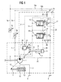
- Fig. 1 shows a first embodiment of the control device according to the invention.
- a adjustable hydraulic pump 1 is driven by a drive unit via a drive shaft 2, z. B. a diesel engine.
- the hydraulic pump 1 draws over the pressure medium a tank line 3 from a pressure medium tank 4 and promotes the pressure medium in a delivery line 5.
- the delivery line 5 branches into two separate delivery lines 5a and 5b, which each lead to separate consumers.
- Delivery lines 5a and 5b each have a metering throttle 6a and 6b.
- the Metering throttles 6a and 6b are used to set the flow rate for the consumer adjustable.
- the metering chokes 6a and 6b can, for. B. designed as a hand control be and be arranged in the cab of a construction machine.
- a generally 7 is used to adjust the delivery volume of the hydraulic pump 1 designated adjusting device.
- Adjusting device 7 from a first actuating cylinder 8, in which a first actuating piston 9 is arranged movably, in connection with the adjusting unit 10 of the hydraulic motor stands.
- a second actuating piston 11 in connection, which is arranged movably in a second actuating cylinder 12 and by means of a swing-out spring 13 is acted on so that the hydraulic pump 1 by the Swinging spring 13 is pivoted in the direction of maximum delivery volume.
- the Hydraulic pump 1 pivoted back towards the minimum displacement.
- the first actuating cylinder 8 and the second actuating cylinder 12 as well as the first actuating piston 9 and the second actuating pistons 11 can also be structurally combined.
- a flow control valve 15 is provided to control the flow rate.
- a first one Control input of the flow control valve 15 is connected via a connecting line 16 a pressure change valve 17 connected.
- the pressure change valve 17 selects the highest control pressure in two first control lines 18a and 18b, each of one assigned delivery line 5a or 5b downstream of that in the delivery lines 5a and 5b provided metering throttle 6a or 6b via a control input X1 or X2 to the Guide pressure change valve 17.
- the flow control valve 15 is also a second Control line 19 with the delivery line 5 upstream of the metering throttles 6a and 6b connected.
- the flow control valve 15 is therefore from the pressure difference of the metering throttle 6a and 6b, which is downstream of the metering valve 6a or 6b have the greatest delivery pressure in each case.
- the flow control valve 15 is in illustrated embodiment formed as a 3/2-way valve.
- the two inputs of the Flow control valve 15 are on the one hand via the first control line 19 with the Delivery line 5 and on the other hand via the tank line 20 with the pressure medium tank 4 connected.
- the Flow control valve 15 sets a control pressure in the connecting line 21, the acts on the cylinder space 14 of the first actuating cylinder 8.
- the valve body of the flow control valve 15 through the Return spring 22 moved so that the connecting line 21 to the pressure medium tank 4 is ventilated.
- adjusting device 7 is a pressure control valve 23 arranged, which serves to limit the pressure in the delivery line 5. Once the Delivery pressure in the delivery line 5 at the outlet of the hydraulic pump 1 through Return spring 24 exceeds the maximum pressure that can be specified Adjusting device 7 leading signal pressure line 25 with an increased signal pressure acted upon by the 3/2-way valve formed in the embodiment Pressure control valve 23 is moved to a control position in which the Second control line 19 acted upon delivery pressure directly with the control pressure line 25 connected is. As a result, the hydraulic pump 1 is pivoted back and an overpressure in the delivery line 5 avoided.
- a throttle chain 26 to the return flow of the pressure medium from the To facilitate cylinder chamber 14 to the pressure medium tank 4.
- a power control valve 27 is provided.
- the power control valve 27 is between the first control line 18b connected to the delivery line 5b and the to the pressure medium tank 4 leading tank line 20 is arranged.
- the power control valve 27 is, on the one hand, due to the control pressure prevailing in the first control line 18b the detour line 28 is acted upon in the opening direction.
- it will Power control valve 27 via a measuring spring arrangement 29 from the adjusting device 7 in Closing direction applied.
- the measuring spring arrangement 29 is between the actuating piston 9 and a valve piston of the power control valve 27, not shown in detail. With increasing pressure in the delivery line 5b downstream of the associated Metering throttle 6b, the power control valve 27 is acted upon in the opening direction.
- the power control valve 27 via the measuring spring arrangement 29 by the Adjustment device 7 is increasingly applied in the closing direction when that Delivery volume of the hydraulic pump 1 reduced.
- a suitable measuring spring arrangement 29 in particular by nesting several springs with different ones Spring constant, a hyperbolic control characteristic can be almost constant Maximum performance can be simulated.
- a power-controlled consumer is connected to the delivery line 5b, while the delivery line 5a is connected to a non-power-controlled second consumer. If only the metering throttle 6a is open, however, the metering throttle 6b is closed, the input X2 is depressurized, while the control input X1 first control line 18a sets a control pressure.
- the pressure change valve 17 connects therefore the first control line 18 with the corresponding control input of the Flow control valve 15 so that the pressure drop in the metering throttle 6a to one constant value is adjusted by the flow control valve 15.
- the control input X2 and thus the first control line 18b are of the corresponding one Control input of the flow control valve separated. The pressure drop at the metering throttle 6b is therefore without influence on the flow control.
- the power control valve 27 via the detour line 28 is also not in A control pressure is applied to the opening direction.
- the power regulation is therefore in not active in this operating state.
- an implement such. B. in Form a hydraulically actuated excavator bucket. During the pure The power control is therefore switched off in excavator operation and an undesirable one Lack of performance does not occur.
- control input X1 is depressurized and control input X2 is above the first Control line 18b is acted upon by the delivery pressure in delivery line 5b.
- the pressure change valve 17 passes the control pressure in the first control line 18b to the Flow control valve 15 during the first connected to the delivery line 5a Control line 18a through the pressure change valve 17 from the flow control valve 15 is separated.
- the flow rate is controlled by means of the flow rate control valve 15. At If the predetermined maximum power is exceeded, the power control valve 27 responds and connects the first control line 18b to the pressure medium tank via the tank line 20 4.
- a hydraulic implement can be on the delivery line 5a Construction machine, e.g. B. the hydraulic actuator for the excavator bucket Backhoe loader, be connected, while on the delivery line 5b of the hydraulic Travel drive of the construction machine can be connected.
- the works Control device according to the invention without power limitation, since the control input X2 is depressurized. Only when the hydraulic travel drive is switched on by opening the Metering throttle 6b, the power control valve 27 is activated and monitors the Power output to the hydraulic travel drive.
- the hydraulic pump 1 is pivoted back to overload the Hydraulic pump 1 via the shaft 2 driving motor, e.g. B. a diesel engine avoid.
- the regulation according to the invention therefore makes an optimal one Power distribution to the working device connected to the delivery line 5a and the achieved at the conveyor line 5b connected drive.
- The is advantageously constructive effort for the control device according to the invention is relatively low. It can the control device known from DE 195 17 974 A1 with minor constructive Modifications are used, so that a special design for the control task according to the invention is not necessary. This will make the Manufacturing costs significantly reduced.
- a choke 30 in the first control line 18b of the power-controlled consumer be provided.
- the throttle can also be connected to the power control valve 27 leading connecting line 31 may be arranged.
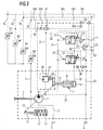
- FIG. 2 shows a second exemplary embodiment of the control device according to the invention shown. While the control device shown in FIG. 1 and already described for connecting a power-controlled consumer and a non-power-controlled one Consumer is provided, two can on the control device shown in Fig. 2 power-controlled consumers and two non-power-controlled consumers be connected. Elements already described are the same Provide reference numerals, so that a repetitive description is unnecessary.
- the delivery line 5 branches in the embodiment shown in FIG a total of four separate delivery lines 5a to 5d.
- Each conveyor line is 5a to 5d
- a respective first control line 18a to 18d is assigned, which via control connections X1 to X4 of the control device according to the invention are supplied.
- power-controlled consumers can be connected, while to the Delivery lines 5a and 5c non-power-controlled consumers can be connected.
- the first pressure change device becomes the highest control pressure in the first Control lines 18a to 18d are selected.
- the first pressure change device consists of the pressure swing valve 17 and the two further pressure swing valves 40 and 41.
- the pressure control valve 41 is the highest control pressure of the two Control lines 18b and 18d selected, which with the delivery lines 5b and 5d are connected to which power-controlled consumers are connected. The on this way, control pressure is preselected via the connecting line 42 Pressure change valve 17 supplied.
- the pressure change valve 40 By means of the pressure change valve 40, the highest in control pressure prevailing between the two control lines 18a and 18c.
- the Control lines 18a and 18c are connected to conveyor lines 5a and 5c, on which non-regulated consumers are connected.
- preselected control pressure is the via a connecting line 43 Pressure change valve 17 supplied, the highest overall control pressure of all first control lines 18a to 18d selects and via the connecting line 16 Flow control valve 15 supplies.
- the flow control follows on the basis all control pressures in all first control lines 18a to 18d.
- the pressure change valve 41 also serves as a second pressure change device to the to select the highest control pressure of those first control lines 18b and 18d with the delivery lines 5b and 5d are connected to which power-controlled consumers are connected.
- the second pressure change device is therefore part of the first Pressure-change device.
- the highest control pressure of the first control lines 18b and 18d is supplied via the connecting line 31 to the power control valve 27, so that the Power control is only based on the control pressures that Delivery lines 5b and 5d come from which power-controlled consumers are connected.
- control device can also be used for others power-controlled or non-power-controlled consumers are expanded.
- control device can also be used for others power-controlled or non-power-controlled consumers are expanded.
- pressure swing valves in the pressure swing devices are each nested in series, so that a corresponding number of connections are available for a corresponding number of consumers.
- the power control valve 27 could also in other ways, for. B. as a hyperbola regulator, be trained.
Landscapes
- Engineering & Computer Science (AREA)
- Mechanical Engineering (AREA)
- General Engineering & Computer Science (AREA)
- Fluid-Pressure Circuits (AREA)
- Operation Control Of Excavators (AREA)
- Control Of Positive-Displacement Pumps (AREA)
Abstract
Description
Die Erfindung betrifft eine Regeleinrichtung für eine Hydropumpe, insbesondere zur Ansteuerung einer Baumaschine, z. B. eines Baggerladers.The invention relates to a control device for a hydraulic pump, in particular for Control of a construction machine, e.g. B. a backhoe loader.
Eine Regeleinrichtung nach dem Oberbegriff des Anspruchs 1 ist aus der
DE 195 17 974 A1 bekannt. Eine ähnlich Regeleinrichtung geht aus der DE 33 45 264 A1
hervor. Bei den bekannten Regelvorrichtungen fördert eine verstellbare Hydropumpe in
eine Förderleitung, die zu einem Verbraucher führt. In der Förderleitung ist eine
verstellbare Förderstromdrossel bzw. Zumeßdrossel vorgesehen, mit welcher der
Förderstrom fiir den Verbraucher vorgegeben wird. Zur Regelung des von der
Hydropumpe geförderten Förderstroms ist ein Förderstromregelventil vorgesehen, daß
über eine erste Steuerleitung mit der Förderleitung stromabwärts der Zumeßdrossel und
über eine zweite Steuerleitung mit der Förderleitung stromaufwärts der Zumeßdrossel
verbunden ist. Der an der Zumeßdrossel auftretende Druckabfall dient daher zur
Ansteuerung des Förderstromregelventils, welches den Stelldruck für eine auf das
Fördervolumen der Hydropumpe einwirkende Verstellvorrichtung regelt. Zusätzlich ist ein
Leistungsregelventil vorgesehen, welches zwischen der ersten Steuerleitung und einem
Druckmedium-Tank angeordnet ist. Das Leistungsregelventil wird in Öffnungsrichtung
von dem Steuerdruck in der ersten Steuerleitung beaufschlagt, während es in
Schließrichtung über eine Meßfederanordnung von der Verstellvorrichtung in
Abhängigkeit von dem durch die Verstellvorrichtung vorgegebenen Fördervolumen der
Hydropumpe beaufschlagt wird. Durch eine geeignete Wahl der Meßfederanordnung läßt
sich die hyperbolische Kennlinie einer vorgegebenen Maximalleistung zumindest
näherungsweise nachbilden. In einem Regelbereich unterhalb der vorgegebenen
Maximalleistung wird die Regelcharakteristik der Regeleinrichtung durch das
Förderstromregelventil bestimmt, welches den Förderstrom der Hydropumpe auf den
durch den Öffnungsquerschnitt der Zumeßdrossel vorgegebenen Wert einregelt. Bei
Überschreiten der vorgegebenen Maximalleistung jedoch spricht das Leistungsregelventil
an und begrenzt den Druck in der ersten Steuerleitung, so daß die Hydropumpe
zurückgeschwenkt und eine Überlastung vermieden wird.A control device according to the preamble of
Grundsätzlich sind die bekannten Regeleinrichtungen auch zur Ansteuerung mehrerer Verbraucher geeignet. In der Praxis stellt sich jedoch das Problem, daß nicht in sämtlichen Betriebszuständen eine Leistungsregelung erforderlich ist. Insbesondere bei Baumaschinen gibt es hydraulische Verbraucher, für welche eine Leistungsregelung erforderlich ist, um eine Überlastung des Antriebsmotors für die Hydropumpe zu vermeiden, während es andere Verbraucher gibt, bei welchen eine Leistungsbegrenzung zu einem unerwünschten Leistungsmangel führt. Z. B. werden bei einem Baggerlader eines oder mehrere hydraulische Arbeitsgeräte sowie ein hydraulischer Fahrantrieb angetrieben. In dem Baggerbetrieb des Baggerladers, in welchem das Fahrzeug an einem festen Standort steht, steht die Antriebsleistung für die Baggerschaufel unbegrenzt zur Verfügung und eine Leistungsbegrenzung würde zu einem unerwünschten Leistungsmangel führen. In einem Laderbetrieb hingegen, bei welchem der Baggerlader durch einen hydraulischen Fahrantrieb fortwährend bewegt wird, muß die zur Verfügung stehende Pumpenleistung auf das oder die Arbeitsgeräte und den Fahrantrieb verteilt werden. Hierbei ist eine Leistungsbegrenzung für den Fahrantrieb erforderlich, um eine Überlastung des die Hydropumpe antreibenden Motors zu vermeiden. Ähnliche Problemstellungen ergeben sich in der Praxis auch für andere Baumaschinen. Basically, the known control devices are also used to control several Suitable for consumers. In practice, however, the problem arises that not all Operating conditions, a power control is required. Especially with construction machines there are hydraulic consumers for which a power control is required to to avoid overloading the drive motor for the hydraulic pump while it is other consumers, where a power limit becomes an undesirable one Lack of performance leads. For example, in a backhoe loader, one or more hydraulic tools and a hydraulic travel drive. By doing Excavator operation of the backhoe loader, in which the vehicle is at a fixed location, there is unlimited drive power for the excavator bucket and one Limiting performance would lead to an undesirable lack of performance. In one Loader operation, however, in which the backhoe loader is operated by a hydraulic Travel drive is constantly moved, the available pump power be distributed to the implement (s) and the drive system. Here is one Power limitation for the travel drive required to overload the the Avoid the hydraulic pump driving motor. Similar problems arise in practice also for other construction machines.
Weiterhin ist aus der DE 36 28 370 A1 eine Hydraulikanlage für Nutzfahrzeuge, insbesondere für Straßenfahrzeuge, bekannt. Diese umfaßt zumindest eine verstellbare Hydropumpe zur Versorgung eines Verbrauchers. Die Hydraulikanlage umfaßt einen Förderstromregler, über den in Abhängigkeit eines Druckdifferenzsignals, welches an einer Meßblende in der Druckleitung zum Verbraucher abgegriffen wird, der Förderstrom geregelt wird. Dabei ist vorgesehen, daß eine verstellbare Hydropumpe zur Versorgung zumindest zweier bei unterschiedlichen Fördermengen und unterschiedlichen Betriebsdrücken arbeitender Verbraucher vorgesehen ist, daß in jeder von der Hydropumpe zu einem Verbraucher führenden Förderleitung eine Blende mit fördermengenabhängigem Querschnitt und bei dem Verbrauchern mit niedrigerem Lastdruck eine Druckwaage angeordnet ist, wobei nach den jeweiligen Blenden ausgehende Steuerdruckleitungen zu dem Fördermengenregler führen.Furthermore, from DE 36 28 370 A1 is a hydraulic system for commercial vehicles, in particular for road vehicles, known. This includes at least one adjustable Hydraulic pump to supply a consumer. The Hydraulic system includes a flow regulator, through which as a function of a pressure difference signal, which at a measuring orifice in the pressure line to the consumer is tapped, the flow rate is regulated. It is provided that an adjustable hydraulic pump for Care of at least two in different Flow rates and different operating pressures working consumer is provided that in each of of the hydraulic pump leading to a consumer Delivery line an orifice with delivery dependent Cross-section and at consumers with lower Load pressure a pressure compensator is arranged, according to the respective orifices outgoing control pressure lines to the Feed rate controller.
Nachteilig bei dem aus der DE 36 28 370 A1 bekannten Hydraulikanlage ist dabei insbesondere, daß keine Leistungsregelung erfolgt. Somit ist es nicht möglich, eine optimale Leistungsverteilung zwischen den verschiedenen Verbrauchern zu erzielen. A disadvantage of that known from DE 36 28 370 A1 Hydraulic system is in particular that none Power regulation takes place. So it is not possible an optimal power distribution between the to reach different consumers.
Der Erfindung liegt daher die Aufgabe zugrunde, eine Regeleinrichtung für eine verstellbare Hydropumpe zu schaffen, mit welcher die Ansteuerung mehrerer Verbraucher so möglich ist, das eine möglichst optimale Leistungsverteilung erzielt wird.The invention is therefore based on the object of a control device for a to create an adjustable hydraulic pump with which the control of several consumers it is possible to achieve the best possible distribution of power.
Die Aufgabe wird durch die kennzeichnenden Merkmale des Anspruchs 1 in Verbindung
mit den gättungsbildenden Merkmalen gelöst.The object is in connection with the characterizing features of
Dabei liegt der Erfindung die Erkenntnis zugrunde, daß eine optimale Leistungsverteilung dadurch erzielt werden kann, daß nur ausgewählte, leistungsgeregelte Verbraucher mit dem Leistungsregelventil in Verbindung stehen, während das Leistungsregelventil von den übrigen Verbrauchern nicht angesprochen wird. Das Förderstromregelventil hingegen ist über eine Druckwechseleinrichtung mit sämtlichen Verbrauchern einschließlich der nicht leistungsgeregelten Verbraucher verbunden. Dabei wird jeweils der höchste Steuerdruck der in den ersten Steuerleitungen herrschenden Steuerdrücke ausgewählt und dem Förderstromregelventil zugeführt. Auf die Leistungsregelung haben daher entsprechend der erfindungsgemäßen Lösung nur diejenigen Verbraucher Einfluß, die tatsächlich zu einer Überlastung des die Hydropumpe antreibenden Antriebsmotors führen können. Für die übrigen Verbraucher wird ein Leistungsmangel durch eine unnötige Leistungsbegrenzung vermieden.The invention is based on the knowledge that an optimal power distribution can be achieved in that only selected, power-controlled consumers with communicate with the power control valve, while the power control valve from the other consumers are not addressed. The flow control valve, however, is via a pressure change device with all consumers including not power-controlled consumers connected. The highest control pressure the control pressures prevailing in the first control lines are selected and the Flow control valve supplied. On the power control therefore have the solution according to the invention influence only those consumers who actually become one Overload of the drive motor driving the hydraulic pump can lead. For the other consumers will experience a lack of performance due to an unnecessary limit on performance avoided.
Die Ansprüche 2 bis 9 beinhalten vorteilhafte Weiterbildungen der Erfindung.
Im einfachsten Fall kann nach Anspruch 2 nur ein einziger leistungsgeregelter Verbraucher vorgesehen sein, dessen erste Steuerleitung. über eine Verbindungsleitung mit dem Leistungsregelventil verbunden ist. Die Verbindungsleitung mündet in die erste Steuerleitung dieses leistungsgeregelten Verbrauchers stromaufwärts der ersten Druckwechseleinrichtung zur Auswahl des Steuerdrucks für das Förderstromregelventil ein. Der leistungsgeregelte Verbraucher bei einer Baumaschine, z. B. einem Baggerlader, kann z. B. der Fahrantrieb sein.In the simplest case, only a single power-controlled consumer can be provided, the first control line. via a connecting line with the Power control valve is connected. The connecting line opens into the first Control line of this power-controlled consumer upstream of the first Pressure change device for selecting the control pressure for the flow control valve on. The power-controlled consumer in a construction machine, e.g. B. a backhoe loader, can e.g. B. be the drive.
Wenn eine Leistungsregelung für mehrere Verbraucher vorzusehen ist, kann der jeweils
höchste Steuerdruck in den ersten Steuerleitungen der Gruppe der leistungsgeregelten
Verbraucher durch eine zweite Druckwechseleinrichtung ausgewählt werden und einer zu
dem Leistungsregelventil führenden Verbindungsleitung entsprechend Anspruch 3
zugeführt werden.If a power regulation is to be provided for several consumers, each can
highest control pressure in the first control lines of the group of power-controlled
Consumers are selected by a second pressure change device and one too
the power control valve leading connecting line according to
In die zu dem Leistungsregelventil führenden Verbindungsleitung kann entsprechend
Anspruch 4 eine Drossel zur Begrenzung der Strömung durch das Leistungsregelventil
vorgesehen sein. Alternativ oder zusätzlich kann diese Drossel auch in jeder einem
leistungsgeregelten Verbraucher zugeordneten ersten Steuerleitung entsprechend Anspruch
5 angeordnet sein.In the connecting line leading to the power control valve can accordingly
Claim 4 a throttle to limit the flow through the power control valve
be provided. Alternatively or additionally, this choke can also be used in each one
power-controlled consumer assigned first control line according to
Die erste und die zweite Druckwechseleinrichtung kann aus einem Druckwechselventil oder mehreren, verschachtelt hintereinander angeordneten Druckwechselventilen entsprechend Anspruch 6 bestehen. Besonders vorteilhaft kann die zweite Druckwechseleinrichtung entsprechend Anspruch 7 Teil der ersten Druckwechseleinrichtung sein. Durch ein letztes Druckwechselventil wird der jeweils höchste Steuerdruck der leistungsgeregelten Verbraucher mit dem jeweils höchsten Steuerdruck der nicht leistungsgeregelten Verbraucher verglichen und für die Ansteuerung des Förderstromregelventils der jeweils insgesamt höchste Steuerdruck ausgewählt. Zwischen den Förderstromregelventilen der Verstellvorrichtung kann zusätzlich entsprechend Anspruch 8 ein Druckregelventil angeordnet sein, daß von dem Steuerdruck in der zweiten Steuerleitung angesteuert ist. Der Steuerdruck in der zweiten Steuerleitung entspricht dem Druck in der Förderleitung am Ausgang der Hydropumpe stromaufwärts der Zumeßdrosseln. Wenn der Ausgangsdruck der Hydropumpe einen vorgegebenen Grenzwert überschreitet, spricht das Druckregelventil an und schwenkt die Hydropumpe zurück.The first and the second pressure change device can consist of a pressure change valve or several pressure exchange valves, nested one behind the other according to claim 6 exist. The second can be particularly advantageous Pressure change device according to claim 7 part of the first Pressure change device. Through a last pressure change valve the highest control pressure of the power-controlled consumers with the highest in each case Control pressure of the non-power-controlled consumers compared and for control the maximum control pressure selected for the flow control valve. In addition, between the flow control valves of the adjustment device According to claim 8, a pressure control valve may be arranged that of the control pressure is controlled in the second control line. The control pressure in the second control line corresponds to the pressure in the delivery line at the outlet of the hydraulic pump upstream the metering chokes. If the output pressure of the hydraulic pump is a predetermined one Exceeds the limit value, the pressure control valve responds and swivels the hydraulic pump back.
Die erfindungsgemäße Regeleinrichtung kann in besonders vorteilhafter Weise zur Ansteuerung einer Baumaschine, insbesondere eines Baggerladers entsprechend Anspruch 9 Verwendung finden. Dabei ist zumindest der Fahrantrieb des Baggerladers ein leistungsgeregelter Verbraucher. The control device according to the invention can be used in a particularly advantageous manner Control of a construction machine, in particular a backhoe loader according to claim 9 Finding use. At least the drive of the backhoe loader is on power-controlled consumer.
Die Erfindung wird nachfolgend unter Bezugnahme auf die Zeichnung näher beschrieben. In der Zeichnung zeigen:
- Fig. 1
- ein erstes Ausführungsbeispiel der erfindungsgemäßen Regeleinrichtung; und
- Fig. 2
- ein zweites Ausführungsbeispiel der erfindungsgemäßen Regeleinrichtung.
- Fig. 1
- a first embodiment of the control device according to the invention; and
- Fig. 2
- a second embodiment of the control device according to the invention.
Fig. 1 zeigt ein erstes Ausführungsbeispiel der erfindungsgemäßen Regeleinrichtung. Eine
verstellbare Hydropumpe 1 wird über eine Antriebswelle 2 von einem Antriebsaggregat,
z. B. einem Dieselmotor, angetrieben. Die Hydropumpe 1 saugt das Druckmedium über
eine Tankleitung 3 aus einem Druckmedium-Tank 4 an und fördert das Druckmedium in
eine Förderleitung 5. Die Förderleitung 5 verzweigt sich in zwei separate Förderleitungen
5a und 5b, die jeweils zu getrennten Verbrauchern führen. In jeder der separaten
Förderleitungen 5a und 5b ist jeweils eine Zumeßdrossel 6a und 6b vorgesehen. Die
Zumeßdrosseln 6a und 6b sind zur Einstellung des Förderstroms für die Verbraucher
einstellbar. Die Zumeßdrosseln 6a und 6b können z. B. als Handsteuergeber ausgebildet
sein und in dem Führerhaus einer Baumaschine angeordnet sein.Fig. 1 shows a first embodiment of the control device according to the invention. A
adjustable
Zur Verstellung des Fördervolumens der Hydropumpe 1 dient eine allgemein mit 7
bezeichnete Verstellvorrichtung. Im in Fig. 1 dargestellten Ausführungsbeispiel besteht die
Verstellvorrichtung 7 aus einem ersten Stellzylinder 8, in welchem ein erster Stellkolben 9
bewegbar angeordnet ist, der mit der Verstelleinheit 10 des Hydromotors in Verbindung
steht. Mit der Verstelleinheit 10 des Hydromotors 1 steht ferner ein zweiter Stellkolben 11
in Verbindung, der in einem zweiten Stellzylinder 12 bewegbar angeordnet ist und mittels
einer Ausschwenkfeder 13 so beaufschlagt wird, daß die Hydropumpe 1 durch die
Ausschwenkfeder 13 in Richtung auf maximales Fördervolumen ausgeschwenkt wird.
Durch Druckbeaufschlagung des Zylinderraumes 14 in dem ersten Stellzylinder 8 wird die
Hydropumpe 1 in Richtung auf minimales Verdrängungsvolumen zurückgeschwenkt. Der
erste Stellzylinder 8 und der zweite Stellzylinder 12 sowie der erste Stellkolben 9 und der
zweite Stellkolben 11 können baulich auch vereinigt sein.A generally 7 is used to adjust the delivery volume of the
Zur Regelung des Förderstroms ist ein Förderstromregelventil 15 vorgesehen. Ein erster
Steuereingang des Förderstromregelventils 15 ist über eine Verbindungsleitung 16 mit
einem Druckwechselventil 17 verbunden. Das Druckwechselventil 17 wählt jeweils den
höchsten Steuerdruck in zwei ersten Steuerleitungen 18a und 18b aus, die jeweils von einer
zugeordneten Förderleitung 5a bzw. 5b stromabwärts der in den Förderleitungen 5a und 5b
vorgesehenen Zumeßdrossel 6a bzw. 6b über einen Steuereingang X1 bzw. X2 zu dem
Druckwechselventil 17 führen. Das Förderstromregelventil 15 ist ferner über eine zweite
Steuerleitung 19 mit der Förderleitung 5 stromaufwärts der Zumeßdrosseln 6a und 6b
verbunden. Das Förderstromregelventil 15 wird daher von der Druckdifferenz an
derjenigen Zumeßdrossel 6a und 6b angesteuert, die stromabwärts des Zumeßventils 6a
bzw. 6b den jeweils größten Förderdruck aufweisen. Das Förderstromregelventil 15 ist im
dargestellten Ausführungsbeispiel als 3/2-Wegeventil ausgebildet. Die beiden Eingänge des
Förderstromregelventils 15 sind über die erste Steuerleitung 19 einerseits mit der
Förderleitung 5 und andererseits über die Tankleitung 20 mit dem Druckmedium-Tank 4
verbunden. Je nach Druckdifferenz zwischen den beiden Steuereingängen des
Förderstromregelventils 15 stellt sich in der Verbindungsleitung 21 ein Stelldruck ein, der
den Zylinderraum 14 des ersten Stellzylinders 8 beaufschlagt. In der Ruhestellung des
Förderstromregelventils 15 wird der Ventilkörper des Förderstromregelventils 15 durch die
Rückstellfeder 22 so verschoben, daß die Verbindungsleitung 21 zum Druckmedium-Tank
4 hin belüftet ist.A
Zwischen dem Förderstromregelventil 15 und dem Zylinderraum 14 der
Verstellvorrichtung 7 ist im dargestellten Ausführungsbeispiel ein Druckregelventil 23
angeordnet, das der Druckbegrenzung in der Förderleitung 5 dient. Sobald der
Förderdruck in der Förderleitung 5 am Ausgang der Hydropumpe 1 einen durch die
Rückstellfeder 24 vorgebbaren Maximaldruck überschreitet wird die zu der
Verstellvorrichtung 7 führende Stelldruckleitung 25 mit einem erhöhten Stelldruck
beaufschlagt, indem das im Ausführungsbeispiel als 3/2-Wegeventil ausgebildete
Druckregelventil 23 in eine Regelstellung verschoben wird, in welchem die mit dem
Förderdruck beaufschlagte zweite Steuerleitung 19 direkt mit der Stelldruckleitung 25
verbunden ist. Dadurch wird die Hydropumpe 1 zurückgeschwenkt und ein Überdruck in
der Förderleitung 5 vermieden.Between the
Im dargestellten Ausführungsbeispiel befindet sich zwischen der Stelldruckleitung 25 und
der Tankleitung 20 eine Drosselkette 26, um den Rückfluß des Druckmediums aus der
Zylinderkammer 14 zum Druckmedium-Tank 4 hin zu erleichtern.In the illustrated embodiment is between the
Zusätzlich ist ein Leistungsregelventil 27 vorgesehen. Das Leistungsregelventil 27 ist
zwischen der mit der Förderleitung 5b verbundenen ersten Steuerleitung 18b und der zu
dem Druckmedium-Tank 4 führende Tankleitung 20 angeordnet. Das Leistungsregelventil
27 wird einerseits durch den in der ersten Steuerleitung 18b herrschenden Steuerdruck über
die Umwegleitung 28 in Öffnungsrichtung beaufschlagt. Andererseits wird das
Leistungsregelventil 27 über eine Meßfederanordnung 29 von der Verstellvorrichtung 7 in
Schließrichtung beaufschlagt. Die Meßfederanordnung 29 ist zwischen dem Stellkolben 9
und einem nicht näher dargestellten Ventilkolben des Leistungsregelventils 27 angeordnet.
Mit zunehmenden Druck in der Förderleitung 5b stromabwärts der zugeordneten
Zumeßdrossel 6b wird das Leistungsregelventil 27 in Öffnungsrichtung beaufschlagt.
Hingegen wird das Leistungsregelventil 27 über die Meßfederanordnung 29 durch die
Verstellvorrichtung 7 zunehmend in Schließrichtung beaufschlagt, wenn sich das
Fördervolumen der Hydropumpe 1 verringert. Durch eine geeignete Meßfederanordnung
29, insbesondere durch die Verschachtelung mehrerer Federn mit unterschiedlicher
Federkonstante, kann eine hyperbolische Regelcharakteristik nahezu konstanter
Maximalleistung nachgebildet werden.In addition, a
Nachfolgend wird die Funktionsweise der erfindungsgemäßen Regeleinrichtung näher beschrieben.The mode of operation of the control device according to the invention is described in more detail below described.
An der Förderleitung 5b ist ein leistungsgeregelter Verbraucher angeschlossen, während an
der Förderleitung 5a ein nicht leistungsgeregelter zweiter Verbraucher angeschlossen ist.
Wenn lediglich die Zumeßdrossel 6a geöffnet ist, die Zumeßdrossel 6b hingegen
geschlossen ist, ist der Eingang X2 drucklos, während sich an dem Steuereingang X1 der
ersten Steuerleitung 18a ein Steuerdruck einstellt. Das Druckwechselventil 17 verbindet
daher die erste Steuerleitung 18 mit dem entsprechenden Steuereingang des
Förderstromregelventils 15, so daß der Druckabfall in der Zumeßdrossel 6a auf einen
konstanten Wert durch das Förderstromregelventil 15 eingeregelt wird. Der Steuereingang
X2 und somit die erste Steuerleitung 18b hingegen sind von dem entsprechenden
Steuereingang des Förderstromregelventils getrennt. Der Druckabfall an der Zumeßdrossel
6b ist daher ohne Einfluß auf die Förderstromregelung. Da der Steuereingang X2 drucklos
ist, wird das Leistungsregelventil 27 über die Umwegleitung 28 ebenfalls nicht in
Öffnungsrichtung mit einem Steuerdruck beaufschlagt. Die Leistungsregelung ist daher in
diesem Betriebszustand nicht aktiv. An der Förderleitung 5a kann ein Arbeitsgerät z. B. in
Form einer hydraulisch betätigbaren Baggerschaufel angeordnet sein. Während des reinen
Baggerbetriebs ist daher die Leistungsregelung abgeschaltet und ein unerwünschter
Leistungsmangel tritt nicht auf.A power-controlled consumer is connected to the
Wenn umgekehrt die Zumeßdrossel 6a geschlossen ist und die Zumeßdrossel 6b geöffnet
ist, ist der Steuereingang X1 drucklos und der Steuereingang X2 ist über die erste
Steuerleitung 18b mit dem Förderdruck in der Förderleitung 5b beaufschlagt. Über das
Druckwechselventil 17 gelangt der Steuerdruck in der ersten Steuerleitung 18b zu dem
Förderstromregelventil 15 während die mit der Förderleitung 5a verbundene erste
Steuerleitung 18a durch das Druckwechselventil 17 von dem Förderstromregelventil 15
getrennt ist. Unterhalb der durch das Leistungsregelventil 27 vorgegebene Maximalleistung
erfolgt eine Förderstromregelung mittels des Förderstromregelventils 15. Bei
Überschreiten der vorgegebenen Maximalleistung spricht das Leistungsregelventil 27 an
und verbindet die erste Steuerleitung 18b über die Tankleitung 20 mit dem Druckmedium-Tank
4. Durch den Druckabfall in der ersten Steuerleitung 18b wird das
Förderstromregelventil 15 im wesentlichen durch den Druck in der zweiten Steuerleitung
19 beaufschlagt, so daß der Stelldruck in der Stelldruckleitung 25 erhöht wird und die
Verstellvorrichtung 7 die Hydropumpe 1 in Richtung auf geringeres Verdrängungsvolumen
zurückschwenkt bis die vorgegebene Maximalleistung wieder unterschritten wird.Conversely, when the
Wie bereits erwähnt, kann an der Förderleitung 5a ein hydraulisches Arbeitsgerät einer
Baumaschine, z. B. die hydraulische Betätigungsvorrichtung für die Baggerschaufel eines
Baggerladers, angeschlossen sein, während an der Förderleitung 5b der hydraulische
Fahrantrieb der Baumaschine angeschlossen sein kann. Solange der Fahrantrieb nicht in
Betrieb gesetzt wird, d. h. solange die Zumeßdrossel 6b geschlossen ist, arbeitet die
erfindungsgemäße Regeleinrichtung ohne Leistungsbegrenzung, da der Steuereingang X2
drucklos ist. Erst bei Zuschalten des hydraulischen Fahrantriebs durch Öffnen der
Zumeßdrossel 6b wird das Leistungsregelventil 27 aktiviert und überwacht die
Leistungsabgabe an den hydraulischen Fahrantrieb. Bei Überschreiten der vorgegebenen
Maximalleistung wird die Hydropumpe 1 zurückgeschwenkt, um eine Überlastung des die
Hydropumpe 1 über die Welle 2 antreibenden Motors, z. B. eines Dieselmotors, zu
vermeiden. Durch die erfindungsgemäße Regelung wird daher eine optimale
Leistungsverteilung auf das an der Förderleitung 5a angeschlossene Arbeitsgerät und den
an der Förderleitung 5b angeschlossenen Fahrantrieb erzielt. Vorteilhafterweise ist der
konstruktive Aufwand für die erfindungsgemäße Regeleinrichtung relativ gering. Es kann
die aus der DE 195 17 974 A1 bekannte Regeleinrichtung mit geringfügigen konstruktiven
Modifikationen verwendet werden, so daß eine Sonderkonstruktion für die
erfindungsgemäße Regelaufgabe nicht notwendig ist. Dadurch werden die
Fertigungskosten erheblich reduziert.As already mentioned, a hydraulic implement can be on the
Um den Strom des Druckmediums durch das Leistungsregelventil 27 zu begrenzen, kann
in der ersten Steuerleitung 18b des leistungsgeregelten Verbrauchers eine Drossel 30
vorgesehen sein. Alternativ kann die Drossel auch in der zu dem Leistungsregelventil 27
führenden Verbindungsleitung 31 angeordnet sein.In order to limit the flow of the pressure medium through the
In Fig. 2 ist ein zweites Ausführungsbeispiel der erfindungsgemäßen Regeleinrichtung dargestellt. Während die in Fig. 1 dargestellte und bereits beschriebenen Regeleinrichtung zum Anschluß eines leistungsgeregelten Verbrauchers und eines nicht leistungsgeregelten Verbrauchers vorgesehen ist, können an der in Fig. 2 dargestellten Regeleinrichtung zwei leistungsgeregelte Verbraucher und zwei nicht leistungsgeregelte Verbraucher angeschlossen werden. Bereits beschriebene Elemente sind mit übereinstimmenden Bezugszeichen versehen, so daß sich insoweit eine wiederholende Beschreibung erübrigt.2 shows a second exemplary embodiment of the control device according to the invention shown. While the control device shown in FIG. 1 and already described for connecting a power-controlled consumer and a non-power-controlled one Consumer is provided, two can on the control device shown in Fig. 2 power-controlled consumers and two non-power-controlled consumers be connected. Elements already described are the same Provide reference numerals, so that a repetitive description is unnecessary.
Die Förderleitung 5 verzweigt sich bei dem in Fig. 2 dargestellten Ausführungsbeispiel in
insgesamt vier separate Förderleitungen 5a bis 5d. Jeder der separaten Förderleitungen 5a
bis 5b ist jeweils eine separate Zumeßdrossel 6a bis 6d zugeordnet, so daß die Zumessung
des Förderstroms für die an den Förderleitungen 5a bis 5d angeschlossenen Verbraucher
von der Bedienperson individuell bemessen werden kann. Jeder Förderleitung 5a bis 5d ist
jeweils eine erste Steuerleitung 18a bis 18d zugeordnet, die über Steueranschlüsse X1 bis
X4 der erfindungsgemäßen Regeleinrichtung zugeführt werden. An die Förderleitungen 5b
und 5d sind jeweils leistungsgeregelte Verbraucher anschließbar, während an die
Förderleitungen 5a und 5c nicht leistungsgeregelte Verbraucher anschließbar sind. In einer
ersten Druckwechseleinrichtung wird der höchste Steuerdruck, der in den ersten
Steuerleitungen 18a bis 18d herrscht, ausgewählt. Die erste Druckwechseleinrichtung
besteht aus dem Druckwechselventil 17 und den beiden weiteren Druckwechselventilen 40
und 41. Mit dem Druckwechselventil 41 wird der jeweils höchste Steuerdruck der beiden
Steuerleitungen 18b und 18d ausgewählt, die mit den Förderleitungen 5b und 5d
verbunden sind, an welchen leistungsgeregelte Verbraucher angeschlossen sind. Der auf
diese Weise vorausgewählt Steuerdruck wird über die Verbindungsleitung 42 dem
Druckwechselventil 17 zugeführt. Mittels des Druckwechselventils 40 wird der höchste in
den beiden Steuerleitungen 18a und 18c herrschende Steuerdruck ausgewählt. Die
Steuerleitungen 18a und 18c sind mit Förderleitungen 5a und 5c verbunden, an welchen
nicht leistungsgeregelte Verbraucher angeschlossen sind. Der auf diese Weise
vorausgewählte Steuerdruck wird über eine Verbindungsleitung 43 dem
Druckwechselventil 17 zugeführt, das den insgesamt höchsten Steuerdruck sämtlicher
erster Steuerleitungen 18a bis 18d auswählt und über die Verbindungsleitung 16 dem
Förderstromregelventil 15 zuführt. Die Förderstromregelung folgt daher auf der Basis
sämtlicher Steuerdrücke in sämtlichen ersten Steuerleitungen 18a bis 18d.The
Das Druckwechselventil 41 dient gleichzeitig als zweite Druckwechseleinrichtung, um den
höchsten Steuerdruck derjenigen ersten Steuerleitungen 18b und 18d auszuwählen, die mit
den Förderleitungen 5b und 5d verbunden sind, an welchen leistungsgeregelte Verbraucher
angeschlossen sind. Die zweite Druckwechseleinrichtung ist somit Teil der ersten
Druckwechseleinrichtung. Der höchste Steuerdruck der ersten Steuerleitungen 18b und 18d
wird über die Verbindungsleitung 31 dem Leistungsregelventil 27 zugeführt, so daß die
Leistungsregelung lediglich auf der Basis derjenigen Steuerdrücke erfolgt, die von
Förderleitungen 5b und 5d stammen, an welchen leistungsgeregelte Verbraucher
angeschlossen sind.The
In entsprechender Weise kann die erfindungsgemäße Regeleinrichtung auch für weitere leistungsgeregelte oder nicht leistungsgeregelte Verbraucher ausgebaut werden. Es sind dazu entsprechend weitere Druckwechselventile in den Druckwechseleinrichtungen vorzusehen, die jeweils verschachtelt seriell hintereinander geschaltet sind, so daß entsprechend viele Anschlüsse für entsprechend viele Verbraucher zur Verfügung stehen.In a corresponding manner, the control device according to the invention can also be used for others power-controlled or non-power-controlled consumers are expanded. There are correspondingly further pressure swing valves in the pressure swing devices to be provided, which are each nested in series, so that a corresponding number of connections are available for a corresponding number of consumers.
Das Leistungsregelventil 27 könnte auch in anderer Weise, z. B. als Hyperbelregler,
ausgebildet sein.The
Claims (9)
- Regulating apparatus for an adjustable hydraulic pump (1), the said apparatus having:characterised in thata delivery flow regulating valve (15) which regulates the delivery flow delivered by the hydraulic pump (1) in dependence upon the pressure medium flowing through a proportioning throttle (6b) in a delivery line (5b) leading to a consuming device, through the fact that the said valve is acted upon by the pressure difference between a first control line (18b) connected to the delivery line (5b) downstream of the proportioning throttle (6b), and a second control line (19) connected to the said delivery line (5b) upstream of the said proportioning throttle (6b), and regulates, in dependence upon this pressure difference, the setting pressure for an adjusting device (7) for adjusting the delivery volume of the hydraulic pump (1); andan output-regulating valve (27) which is disposed between the first control line (18b) and a pressure medium tank (4), the control pressure in the first control line (18b) acting upon the output-regulating valve (27) in the direction of opening, and the adjusting device (7) acting upon the output-regulating valve (27) via a measuring spring arrangement (29) in the direction of closing;
a number of consuming devices, which are each connected to the hydraulic pump (1) via a separate delivery line (5a-5d) in each of which an adjustable proportioning throttle (6a-6d) is disposed, can be activated by the regulating apparatus;
that a first control line (18a-18d) is, in each case, connected, downstream of the associated proportioning throttle (6a-6d), to the delivery line (5a-5d) leading to the associated consuming device;
that a first pressure-changing apparatus (17, 40, 41) selects, in each case, the highest of the control pressures prevailing in the first control lines (18a-18d) and feeds it to the delivery flow regulating valve (15); and
that the output-regulating valve (27) is connected only to the first control lines (18b, 18d) of selected, output-regulated consuming devices, and the first control lines (18a, 18c) of the remaining consuming devices, which are not output-regulated, are separated from the output-regulating valve (27). - Regulating apparatus according to claim 1
characterised in that
the output-regulating valve (27) is connected to the first control line (18b) of a single output-regulated consuming device via a connecting line (31) which opens into the said first control line (18b) of this output-regulated consuming device, upstream of the first pressure-changing apparatus (17). - Regulating apparatus according to claim 1,
characterised in that
the output-regulating valve (27) is connected to the first control lines (18b, 18d) of a group of a number of output-regulated consuming devices via a connecting line (31); and that there is provided, between a connecting line (31) leading to the output-regulating valve (27) and the first control lines (18b, 18d) of the output-regulated consuming devices, a second pressure-changing apparatus (41) which selects, in each case, the highest of the control pressures prevailing in the first control lines (18b, 18d) of the group of output-regulated consuming devices, and feeds it to the connecting line (31). - Regulating apparatus according to one of claims 2 or 3,
characterised in that
a throttle is disposed in the connecting line (31) leading to the output-regulating valve (27). - Regulating apparatus according to one of claims 1 to 4,
characterised in that
a throttle (30; 30a, 30b) is disposed in each first control line (18b, 18d) associated with an output-regulated consuming device. - Regulating apparatus according to one of claims 1 to 5,
characterised in that
the first and second pressure-changing apparatus (17, 40, 41; 41) consists of a pressure-changing valve or a number of pressure-changing valves disposed in an interlaced manner one behind another. - Regulating apparatus according to claim 6,
characterised in that
the second pressure-changing apparatus (41) is part of the first pressure-changing apparatus (17, 40, 41). - Regulating apparatus according to one of claims 1 to 7,
characterised in that
a pressure-regulating valve (23), which is activated by the control pressure in the second control line (19), is disposed between the delivery flow regulating valve (15) and the adjusting device (7). - Regulating apparatus according to one of claims 1 to 8,
characterised in that
the said regulating device serves to activate a construction machine, in particular a backhoe loader, having at least one hydraulic working implement and a travelling mechanism, the working implement being connected to a delivery line (5a) for a consuming device which is not output-regulated, and the travelling mechanism being connected to a delivery line (5b) for an output-regulated consuming device.
Applications Claiming Priority (3)
| Application Number | Priority Date | Filing Date | Title |
|---|---|---|---|
| DE19742157A DE19742157C2 (en) | 1997-09-24 | 1997-09-24 | Control device for an adjustable hydraulic pump with several consumers |
| DE19742157 | 1997-09-24 | ||
| PCT/EP1998/006083 WO1999015792A1 (en) | 1997-09-24 | 1998-09-24 | Regulating device for an adjustable hydraulic pump with several consumers |
Publications (2)
| Publication Number | Publication Date |
|---|---|
| EP1017942A1 EP1017942A1 (en) | 2000-07-12 |
| EP1017942B1 true EP1017942B1 (en) | 2003-06-11 |
Family
ID=7843480
Family Applications (1)
| Application Number | Title | Priority Date | Filing Date |
|---|---|---|---|
| EP98951462A Expired - Lifetime EP1017942B1 (en) | 1997-09-24 | 1998-09-24 | Regulating device for an adjustable hydraulic pump with several consumers |
Country Status (5)
| Country | Link |
|---|---|
| US (1) | US6311489B1 (en) |
| EP (1) | EP1017942B1 (en) |
| CA (1) | CA2292417C (en) |
| DE (2) | DE19742157C2 (en) |
| WO (1) | WO1999015792A1 (en) |
Families Citing this family (8)
| Publication number | Priority date | Publication date | Assignee | Title |
|---|---|---|---|---|
| DE19953170B4 (en) * | 1999-11-04 | 2004-08-12 | Brueninghaus Hydromatik Gmbh | Power control device and valve block for a power control device |
| DE10219850B3 (en) * | 2002-05-03 | 2004-02-05 | Brueninghaus Hydromatik Gmbh | Control device with limit control valve |
| DE10343016B4 (en) * | 2003-09-17 | 2010-08-26 | Brueninghaus Hydromatik Gmbh | Hydraulic control and positioning system with volume compensation |
| KR100752115B1 (en) * | 2004-12-30 | 2007-08-24 | 두산인프라코어 주식회사 | Hydraulic pump control system for an excavator |
| WO2008022672A1 (en) * | 2006-08-21 | 2008-02-28 | Joma-Hydromechanic Gmbh | Feed pump |
| US8621860B2 (en) | 2010-10-22 | 2014-01-07 | Cnh America Llc | Control system for work vehicle |
| DE102018210720A1 (en) * | 2018-06-29 | 2020-01-02 | Robert Bosch Gmbh | Hydrostatic drive with pressure cut-off and method for calibrating the pressure cut-off |
| DE102018210685A1 (en) | 2018-06-29 | 2020-01-02 | Robert Bosch Gmbh | Hydrostatic drive and method for controlling the hydrostatic drive |
Family Cites Families (6)
| Publication number | Priority date | Publication date | Assignee | Title |
|---|---|---|---|---|
| DE3345264A1 (en) * | 1983-12-14 | 1985-06-27 | Brueninghaus Hydraulik Gmbh, 7240 Horb | TORQUE CONTROL UNIT FOR AN ADJUSTABLE HYDROPUMP |
| DE3410071C2 (en) | 1984-03-20 | 1994-06-01 | Bosch Gmbh Robert | Hydraulic system |
| DE3628370A1 (en) * | 1986-08-21 | 1988-02-25 | Beilhack Maschf Martin | Hydraulic system for commercial vehicles especially road vehicles |
| JPH04173433A (en) * | 1990-11-06 | 1992-06-22 | Toyota Autom Loom Works Ltd | Hydraulic system for vehicle |
| JPH0599126A (en) | 1991-10-07 | 1993-04-20 | Komatsu Ltd | Capacity control device for variable capacity type hydraulic pump |
| DE19517974A1 (en) * | 1995-05-16 | 1996-11-21 | Brueninghaus Hydromatik Gmbh | Slidable hydraulic power or torque control device |
-
1997
- 1997-09-24 DE DE19742157A patent/DE19742157C2/en not_active Expired - Fee Related
-
1998
- 1998-09-24 WO PCT/EP1998/006083 patent/WO1999015792A1/en active IP Right Grant
- 1998-09-24 US US09/509,243 patent/US6311489B1/en not_active Expired - Fee Related
- 1998-09-24 CA CA002292417A patent/CA2292417C/en not_active Expired - Fee Related
- 1998-09-24 EP EP98951462A patent/EP1017942B1/en not_active Expired - Lifetime
- 1998-09-24 DE DE59808716T patent/DE59808716D1/en not_active Expired - Lifetime
Also Published As
| Publication number | Publication date |
|---|---|
| DE19742157C2 (en) | 1999-07-01 |
| DE19742157A1 (en) | 1999-04-01 |
| DE59808716D1 (en) | 2003-07-17 |
| WO1999015792A1 (en) | 1999-04-01 |
| US6311489B1 (en) | 2001-11-06 |
| CA2292417A1 (en) | 1999-04-01 |
| EP1017942A1 (en) | 2000-07-12 |
| CA2292417C (en) | 2007-11-20 |
Similar Documents
| Publication | Publication Date | Title |
|---|---|---|
| EP3567167B1 (en) | Hydraulic control system for an assembly of mobile working machines and assembly of mobile working machines | |
| EP0053323B1 (en) | Hydrostatic transmission system with a variable pump and several actuators | |
| EP0826110B1 (en) | Sliding hydraulic output and moment regulation device | |
| EP0149787B2 (en) | Feed controlling device for a variable hydropump | |
| DE4137963C2 (en) | Valve arrangement for load-independent control of several hydraulic consumers | |
| EP1989450B1 (en) | Hydraulic control arrangement | |
| EP0564939B1 (en) | Hydraulic control system for several motors | |
| DE19615593B4 (en) | Hydrostatic drive system | |
| DE4235707B4 (en) | Hydrostatic drive system | |
| DE3508339A1 (en) | Control valve arrangement, consisting of two control blocks, for several hydraulic drives, in particular of mobile appliances | |
| EP1017942B1 (en) | Regulating device for an adjustable hydraulic pump with several consumers | |
| DE10343016B4 (en) | Hydraulic control and positioning system with volume compensation | |
| DE10219717B3 (en) | Hydraulic valve arrangement | |
| CH700344B1 (en) | Control device for at least two hydraulic drives. | |
| EP0190431B1 (en) | Hydraulic system | |
| DE1041813B (en) | Device for cornering stabilization, especially in motor vehicles | |
| DE3609399C2 (en) | ||
| WO1988006114A1 (en) | Hydraulic device with regulable pump | |
| DE3146513C2 (en) | ||
| DE4136813C2 (en) | Working fluid circuit for a control loop of an active wheel suspension of a vehicle | |
| DE3146540C2 (en) | ||
| DE2943994B1 (en) | Hydraulic lifting device for tools, especially on tractors | |
| DE3146561A1 (en) | Hydrostatic drive with pressure control | |
| DE2239288C3 (en) | Hydraulic servo motor system with two consumer circuits | |
| DE19957027A1 (en) | Hydrostatic drive system has measurement aperture for further load reducible depending on load on drive motor for simultaneously driving preferred load and further load |
Legal Events
| Date | Code | Title | Description |
|---|---|---|---|
| PUAI | Public reference made under article 153(3) epc to a published international application that has entered the european phase |
Free format text: ORIGINAL CODE: 0009012 |
|
| 17P | Request for examination filed |
Effective date: 19991020 |
|
| AK | Designated contracting states |
Kind code of ref document: A1 Designated state(s): DE FR GB IT SE |
|
| 17Q | First examination report despatched |
Effective date: 20020801 |
|
| GRAH | Despatch of communication of intention to grant a patent |
Free format text: ORIGINAL CODE: EPIDOS IGRA |
|
| GRAH | Despatch of communication of intention to grant a patent |
Free format text: ORIGINAL CODE: EPIDOS IGRA |
|
| GRAA | (expected) grant |
Free format text: ORIGINAL CODE: 0009210 |
|
| AK | Designated contracting states |
Designated state(s): DE FR GB IT SE |
|
| REG | Reference to a national code |
Ref country code: GB Ref legal event code: FG4D Free format text: NOT ENGLISH |
|
| GBT | Gb: translation of ep patent filed (gb section 77(6)(a)/1977) | ||
| REF | Corresponds to: |
Ref document number: 59808716 Country of ref document: DE Date of ref document: 20030717 Kind code of ref document: P |
|
| REG | Reference to a national code |
Ref country code: SE Ref legal event code: TRGR |
|
| ET | Fr: translation filed | ||
| PLBE | No opposition filed within time limit |
Free format text: ORIGINAL CODE: 0009261 |
|
| STAA | Information on the status of an ep patent application or granted ep patent |
Free format text: STATUS: NO OPPOSITION FILED WITHIN TIME LIMIT |
|
| 26N | No opposition filed |
Effective date: 20040312 |
|
| PGFP | Annual fee paid to national office [announced via postgrant information from national office to epo] |
Ref country code: SE Payment date: 20110923 Year of fee payment: 14 Ref country code: GB Payment date: 20110923 Year of fee payment: 14 Ref country code: FR Payment date: 20111005 Year of fee payment: 14 |
|
| PGFP | Annual fee paid to national office [announced via postgrant information from national office to epo] |
Ref country code: IT Payment date: 20110927 Year of fee payment: 14 |
|
| PGFP | Annual fee paid to national office [announced via postgrant information from national office to epo] |
Ref country code: DE Payment date: 20121122 Year of fee payment: 15 |
|
| PG25 | Lapsed in a contracting state [announced via postgrant information from national office to epo] |
Ref country code: SE Free format text: LAPSE BECAUSE OF NON-PAYMENT OF DUE FEES Effective date: 20120925 |
|
| REG | Reference to a national code |
Ref country code: SE Ref legal event code: EUG |
|
| GBPC | Gb: european patent ceased through non-payment of renewal fee |
Effective date: 20120924 |
|
| REG | Reference to a national code |
Ref country code: FR Ref legal event code: ST Effective date: 20130531 |
|
| PG25 | Lapsed in a contracting state [announced via postgrant information from national office to epo] |
Ref country code: GB Free format text: LAPSE BECAUSE OF NON-PAYMENT OF DUE FEES Effective date: 20120924 |
|
| PG25 | Lapsed in a contracting state [announced via postgrant information from national office to epo] |
Ref country code: FR Free format text: LAPSE BECAUSE OF NON-PAYMENT OF DUE FEES Effective date: 20121001 Ref country code: IT Free format text: LAPSE BECAUSE OF NON-PAYMENT OF DUE FEES Effective date: 20120924 |
|
| REG | Reference to a national code |
Ref country code: DE Ref legal event code: R119 Ref document number: 59808716 Country of ref document: DE Effective date: 20140401 |
|
| PG25 | Lapsed in a contracting state [announced via postgrant information from national office to epo] |
Ref country code: DE Free format text: LAPSE BECAUSE OF NON-PAYMENT OF DUE FEES Effective date: 20140401 |