EP1017137B1 - Cable clamp - Google Patents
Cable clamp Download PDFInfo
- Publication number
- EP1017137B1 EP1017137B1 EP99890357A EP99890357A EP1017137B1 EP 1017137 B1 EP1017137 B1 EP 1017137B1 EP 99890357 A EP99890357 A EP 99890357A EP 99890357 A EP99890357 A EP 99890357A EP 1017137 B1 EP1017137 B1 EP 1017137B1
- Authority
- EP
- European Patent Office
- Prior art keywords
- conical
- cable
- housing
- cone
- segments
- Prior art date
- Legal status (The legal status is an assumption and is not a legal conclusion. Google has not performed a legal analysis and makes no representation as to the accuracy of the status listed.)
- Expired - Lifetime
Links
Images

Classifications
-
- H—ELECTRICITY
- H01—ELECTRIC ELEMENTS
- H01R—ELECTRICALLY-CONDUCTIVE CONNECTIONS; STRUCTURAL ASSOCIATIONS OF A PLURALITY OF MUTUALLY-INSULATED ELECTRICAL CONNECTING ELEMENTS; COUPLING DEVICES; CURRENT COLLECTORS
- H01R13/00—Details of coupling devices of the kinds covered by groups H01R12/70 or H01R24/00 - H01R33/00
- H01R13/46—Bases; Cases
- H01R13/52—Dustproof, splashproof, drip-proof, waterproof, or flameproof cases
- H01R13/5205—Sealing means between cable and housing, e.g. grommet
-
- H—ELECTRICITY
- H01—ELECTRIC ELEMENTS
- H01R—ELECTRICALLY-CONDUCTIVE CONNECTIONS; STRUCTURAL ASSOCIATIONS OF A PLURALITY OF MUTUALLY-INSULATED ELECTRICAL CONNECTING ELEMENTS; COUPLING DEVICES; CURRENT COLLECTORS
- H01R13/00—Details of coupling devices of the kinds covered by groups H01R12/70 or H01R24/00 - H01R33/00
- H01R13/58—Means for relieving strain on wire connection, e.g. cord grip, for avoiding loosening of connections between wires and terminals within a coupling device terminating a cable
- H01R13/5804—Means for relieving strain on wire connection, e.g. cord grip, for avoiding loosening of connections between wires and terminals within a coupling device terminating a cable comprising a separate cable clamping part
- H01R13/5816—Means for relieving strain on wire connection, e.g. cord grip, for avoiding loosening of connections between wires and terminals within a coupling device terminating a cable comprising a separate cable clamping part for cables passing through an aperture in a housing wall, the separate part being captured between cable and contour of aperture
Definitions
- the present invention relates to a cable clamp for watertight pull and torsion protection of electrical cables according to the preamble of claim 1.
- a cable clamp is known from WO 96/13080.
- Cable clamps are used, for example, when electrical conductors introduced into electrical apparatus should be. Outside these devices, the electrical conductor in cables. At the transition from Cable in the electrical apparatus it is necessary that Secure cable against tension and twist, as well as Ingress of water from outside into the electrical apparatus to prevent.
- Known cable clamps consist of several housing parts, which are screwed together. By screwing together Press on the inside of at least one housing part arranged cone-shaped elements on a concentric to the housing parts arranged cone part, in whose centric bore the cable is guided.
- Disadvantage of Cable clamps according to the prior art is the fact that the cone part made essentially from one piece is. This occurs when the cone part is compressed from the outside to a high resistance through the cone part itself and it is only a limited narrowing of the centric bore of the cone part possible, however equate to the limitation of possibility on the guided in the centric bore cable one Exercise pressure.
- the cone parts of the Cable clamps to ensure a pull and torsion protection, that is, they must have a high strength around the to be able to exert the required holding force on the cable.
- such conical parts have a certain Have elasticity to the requirement of Waterproofing and acting as a seal.
- the aim of the invention is therefore a cable clamp the above mentioned type, which is both optimal against water ingress protects as well as in terms of a train and Anti-rotation provides optimal safety and the one larger diameter range of the cables to be clamped as Cover existing cable clamps.
- the clamping area the Konus presses be extended arbitrarily without the Diameter of the housing must therefore be increased because the outer diameter of the cone part by the Inside diameter of the housing union nut is limited.
- the cylinder segments is indeed the area that for the clamping of the cable sheath is responsible extended, but without the outer diameter of the cone part to enlarge.
- claims 3 and 4 cause by different choice of material of the two sections on Cone part, on the different tasks of the two Sections can be entered even better. This is done the vote on the tasks not only by the different forms of the two sections of the Konus presses but also by the choice of materials. While for that section, which is for waterproofing against water responsible is a very elastic, deformable material, can be selected, which adapts to the cable sheath, so is that section of the cone part that is used for the train and Elongation is responsible, from firmer, harder Material manufactured to the required holding forces to exercise the cable.
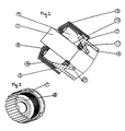
- Fig. 1 is a cable 1, in the electrical conductor. 2 are guided, in the central bore of a cone part 12 led.
- the cone part 12 has in the axial direction 13 of the Cone divided cone segments 9, which in that End portion of the cone part 12 with the larger Outer diameter in cylinder segments 14 pass over. In that End portion of the cone part 12 with smaller Outer diameter are the cone segments 9 via a Sealing lip 11 connected together.
- the connection takes place on both chemical and mechanical Way in which in an injection mold in two steps different materials are injected.
- Axial direction 13 of the cone part seen on both sides is one with a corrugation 6 and a captive 7 (see Fig. 3) provided housing union nut 5 and a Housing base 4 is arranged.
- Both parts have one each self-locking thread 3.16, which connects the allows both parts.
- the housing base 4 can further provided with a coupling plug-in device 15 be or as a connection to a machine housing (not drawn) and points in the area of Thread 3 on the inside a conical inward standing extension 17 (see Fig. 2).
Landscapes
- Cable Accessories (AREA)
- Installation Of Indoor Wiring (AREA)
- Sealing Devices (AREA)
- Insulated Conductors (AREA)
Abstract
Description
Die vorliegende Erfindung bezieht sich auf eine Kabelklemme zur wasserdichten Zug- und Verdrehsicherung von elektrischen Kabeln gemäß dem Oberbegrift des Anspruches 1. Eine derartige Kabelklemme ist aus WO 96/13080 bekannt.The present invention relates to a cable clamp for watertight pull and torsion protection of electrical cables according to the preamble of claim 1. Such a cable clamp is known from WO 96/13080.
Kabelklemmen finden zum Beispiel Verwendung wenn elektrische Leiter in elektrische Apparate eingeführt werden sollen. Außerhalb dieser Apparate werden die elektrischen Leiter in Kabeln geführt. Beim Übergang vom Kabel in den elektrischen Apparat ist es erforderlich das Kabel gegen Zug und Verdrehung zu sichern, sowie das Eindringen von Wasser von außen in den elektrischen Apparat zu verhindern.Cable clamps are used, for example, when electrical conductors introduced into electrical apparatus should be. Outside these devices, the electrical conductor in cables. At the transition from Cable in the electrical apparatus it is necessary that Secure cable against tension and twist, as well as Ingress of water from outside into the electrical apparatus to prevent.
Weitere Kabelklemmen sind aus US-A5 410 104, US-A-4 767 135, DE 20 22 879 A und US-A-4 306 698 bekannt.Further cable clamps are known from US-A-4 410 104, US-A-4 767 135, DE 20 22 879 A and US Pat. No. 4,306,698.
Bekannte Kabelklemmen bestehen aus mehreren Gehäuseteilen, die zusammengeschraubt werden. Durch das Zusammenschrauben drücken an der Innenseite mindestens eines Gehäuseteiles angeordnete konusförmige Elemente auf einen konzentrisch zu den Gehäuseteilen angeordneten Konusteil, in dessen zentrischer Bohrung das Kabel geführt ist. Nachteil der Kabelklemmen nach dem Stand der Technik ist die Tatsache, daß der Konusteil im wesentlichen aus einem Stück gefertigt ist. Dadurch kommt es beim Zusammendrücken des Konusteiles von außen zu einem hohen Widerstand durch den Konusteil selbst und es ist nur eine eingeschränkte Verengung der zentrischen Bohrung des Konusteiles möglich, was jedoch gleichzusetzen ist mit der Einschränkung der Möglichkeit auf das in der zentrischen Bohrung geführte Kabel einen Druck auszuüben. Weiters müssen die Konusteile der Kabel klemmen eine Zug- und Verdrehsicherung gewährleisten, das heißt sie müssen eine hohe Festigkeit aufweisen um die erforderliche Haltekraft auf das Kabel ausüben zu können. Andererseits müssen solche Konusteile eine gewisse Elastizität aufweisen um das Erfordernis der Wasserdichtheit zu erfüllen und als Dichtung zu fungieren. Diese beiden Erfordernisse sind durch die Wahl eines einzigen Materials, wie dies bei Kabelklemmen nach dem Stand der Technik der Fall ist, nur bedingt zu erfüllen, das heißt ein Konusteil der auf optimale Zug- und Verdrehsicherung ausgelegt ist, erfüllt nur bedingt das Erfordernis der Wasserdichtheit und umgekehrt. Known cable clamps consist of several housing parts, which are screwed together. By screwing together Press on the inside of at least one housing part arranged cone-shaped elements on a concentric to the housing parts arranged cone part, in whose centric bore the cable is guided. Disadvantage of Cable clamps according to the prior art is the fact that the cone part made essentially from one piece is. This occurs when the cone part is compressed from the outside to a high resistance through the cone part itself and it is only a limited narrowing of the centric bore of the cone part possible, however equate to the limitation of possibility on the guided in the centric bore cable one Exercise pressure. Furthermore, the cone parts of the Cable clamps to ensure a pull and torsion protection, that is, they must have a high strength around the to be able to exert the required holding force on the cable. On the other hand, such conical parts have a certain Have elasticity to the requirement of Waterproofing and acting as a seal. These two requirements are made by choosing one single material, as with cable clamps after the State of the art the case is to fulfill only conditionally that is a cone part of the optimal train and Anti-rotation is designed, only partially meets the Requirement of watertightness and vice versa.
Ziel der Erfindung ist daher eine Kabelklemme der eingangs erwähnten Art, die sowohl optimal gegen Wassereintritt schützt als auch hinsichtlich einer Zug- und Verdrehsicherung optimale Sicherheit bietet und die einen größeren Durchmesserbereich der zu klemmenden Kabeln als bisherige Kabelklemmen abdecken.The aim of the invention is therefore a cable clamp the above mentioned type, which is both optimal against water ingress protects as well as in terms of a train and Anti-rotation provides optimal safety and the one larger diameter range of the cables to be clamped as Cover existing cable clamps.
Erfindungsgemäß wird dies durch die kennzeichnenden Merkmale des Anspruches 1 erreicht.According to the invention this is characterized by the characterizing Features of claim 1 achieved.
Dadurch sind unterschiedliche Bereiche des Konusteiles für unterschiedliche Aufgaben zuständig. Jener Bereich des Konusteiles, der die Kegelsegmente aufweist dient als Zugund Verdrehsicherung, wogegen die Dichtlippe lediglich zur Abdichtung gegen Wassereintritt dient. Weiters ermöglichen die Freiräume zwischen den einzelnen Kegelsegmenten, daß der gesamte Konusteil sehr stark zusammengepreßt werden kann, was zum Beispiel bei dünneren Kabeln notwendig ist, aber andererseits auch bei dickeren Kabeln zur Anwendung kommen kann. Es ist daher nicht erforderlich, unterschiedliche Konusteile für verschiedene Kabeldurchmesser zu verwenden, wie dies bei Kabelklemmen nach dem Stand der Technik der Fall ist. Die Verbindung der Segmente durch eine Dichtlippe ermöglicht die Abdeckung eines wesentlich größeren Durchmesserbereiches der zu klemmenden Kabeln als bisher.As a result, different areas of the cone part for responsible for different tasks. That area of the Tapered part, which has the cone segments serves as Zugund Anti-rotation, whereas the sealing lip only for Seal against water entry is used. Further enable the free spaces between the individual cone segments, that the entire cone part are pressed together very strongly can, for example, what is necessary with thinner cables, but on the other hand also with thicker cables for the application can come. It is therefore not necessary different cone parts for different Cable diameter to use, as with cable clamps According to the prior art is the case. The connection of Segments through a sealing lip allows the cover a much larger diameter range of clamping cables than before.
Durch die leichte Durchmesseranpassung des Konusteiles und der dadurch erzielbaren hohen Anpreßkraft der Innenseite des Konusteiles an den Kabelmantel ist die erfindungsgemäße Kabelklemme auch unempfindlich gegen unterschiedliche Kabelmantelausführungen. So macht es keinen Unterschied ob der Kabelmantel aus PVC, Gummi oder aber anderen Materialien gefertigt ist.Due to the slight diameter adjustment of the cone part and the thereby achievable high contact pressure of the inside the cone part to the cable sheath is the invention Cable clamp also insensitive to different Cable jacket construction. So it makes no difference if the cable sheath made of PVC, rubber or other Materials is made.
Auch ist die Durchführung des Kabels durch den Konusteil sehr einfach, da die zentrische Bohrung in unbelastetem Zustand sehr groß sein kann, durch die hohe Verformbarkeit der Kegelsegmente und der Dichtlippe jedoch keinerlei Nachteil beim Aufbringen der Preßkraft auf den Kabelmantel entsteht.Also, the passage of the cable through the cone part very simple, as the centric bore in unloaded Condition can be very large, due to the high ductility However, the cone segments and the sealing lip no Disadvantage when applying the pressing force on the cable sheath arises.
Durch die Merkmale des Anspruches 2 kann der Klemmbereich
des Konusteiles beliebig verlängert werden, ohne daß der
Durchmesser des Gehäuses deswegen vergrößert werden muß, da
der Außendurchmesser des Konusteiles durch den
Innendurchmessers der Gehäuseüberwurfmutter beschränkt ist.
Durch die Zylindersegmente wird zwar der Bereich, der für
die Klemmung des Kabelmantels zuständig ist verlängert,
ohne aber den Außendurchmesser des Konusteiles zu
vergrößern.Due to the features of
Die Merkmale der Ansprüche 3 und 4 bewirken, daß durch
unterschiedliche Materialwahl der beiden Abschnitte am
Konusteil, auf die unterschiedlichen Aufgaben der beiden
Abschnitte noch besser eingegangen werden kann. So erfolgt
die Abstimmung auf die Aufgaben nicht nur durch die
unterschiedlichen Formen der beiden Abschnitte des
Konusteiles sondern auch durch die Materialwahl. Während
für jenen Abschnitt, der für die Abdichtung gegen Wasser
zuständig ist ein sehr elastisches, verformbares Material,
gewählt werden kann, das sich dem Kabelmantel anpaßt, so
ist jener Abschnitt des Konusteiles, der für die Zug- und
Verdrehsicherung zuständig ist, aus festerem, härterem
Material gefertigt, um die erforderlichen Haltekräfte auf
das Kabel auszuüben.The features of
Im folgenden erfolgt nun eine detaillierte Beschreibung der Erfindung. Dabei zeigen:
- Fig. 1
- eine axonometrische Ansicht einer erfindungsgemäßen Kabelklemme in aufgeschraubtem Zustand
- Fig. 2
- eine Schnittansicht einer erfindungsgemäßen Kabel klemme
- Fig. 3
- eine axonometrische Ansicht der Gehäuseüberwurfmutter
- Fig. 1
- an axonometric view of a cable clamp according to the invention in a screwed-on state
- Fig. 2
- a sectional view of a cable clamp according to the invention
- Fig. 3
- an axonometric view of the housing union nut
In Fig. 1 ist ein Kabel 1, in dem elektrische Leiter 2
geführt sind, in der zentrischen Bohrung eines Konusteiles
12 geführt. Der Konusteil 12 weist in Achsrichtung 13 des
Kegels unterteilte Kegelsegmente 9 auf, die in jenem
Endbereich des Konusteiles 12 mit dem größeren
Außendurchmesser in Zylindersegmente 14 übergehen. In jenem
Endbereich des Konusteiles 12 mit kleinerem
Außendurchmesser sind die Kegelsegmente 9 über eine
Dichtlippe 11 miteinander verbunden. Die Verbindung
erfolgt sowohl auf chemischen als auch auf mechanischem
Weg, in dem in eine Spritzgußform in zwei Arbeitsschritten
unterschiedliche Materialien eingespritzt werden. In
Achsrichtung 13 des Konusteiles gesehen zu beiden Seiten
ist eine mit einer Riffelung 6 und einer Verliersicherung 7
(siehe Fig. 3) versehene Gehäuseüberwurfmutter 5 und ein
Gehäusegrundteil 4 angeordnet. Beide Teile weisen je ein
selbsthemmendes Gewinde 3,16 auf, das eine Verbindung der
beiden Teile ermöglicht. Der Gehäusegrundteil 4 kann
weiters mit einer Kupplungssteckvorrichtung 15 versehen
sein oder als Anschluß an ein Maschinengehäuse (nicht
gezeichnet) verwendet werden und weist im Bereich des
Gewindes 3 an der Innenseite einen kegelförmig nach innen
stehenden Fortsatz 17 (siehe Fig. 2).In Fig. 1 is a cable 1, in the electrical conductor. 2
are guided, in the central bore of a cone part
12 led. The cone part 12 has in the
Um die wasserdichte Zug- und Verdrehsicherung zu
aktivieren, werden Gehäuseüberwurfmutter 5 und
Gehäusegrundteil 4 zusammengeschraubt bis ein Bund 8 der
Gehäuseüberwurfmutter 5 mit den Zylindersegmenten 14 des
Konusteiles 12 zur Anlage gebracht ist. Durch die in
Achsrichtung 13 verlaufende Bewegung wird auf den
Konusteil 12, speziell auf die Kegelsegmente 9 des
Konusteiles 12 durch den Fortsatz 17 eine Kraft ausgeübt,
die neben der Komponente in Achsrichtung auch eine radiale
Komponente aufweist, und die Kegelsegmente 9
zusammendrückt, so daß eine Haltekraft auf den Kabelmantel
des in der zentrischen Bohrung des Konusteiles 12 geführten
Kabels 1 ausgeübt wird. Weiters wird auch eine radiale
Kraftkomponente auf Dichtlippe 11 ausgeübt, wodurch diese,
gegen den Kabelmantel gepreßt wird und so das Eindringen
von Wasser in das Maschinengehäuse verhindert.To the watertight pull and twist lock too
Activate shell nut 5 and
Claims (4)
- A cable clamp for providing security against straining and twisting of electric cables in a water-proof fashion, with a housing made up of at least one housing union nut (5) and a housing base part (4) which are both provided with cable lead-through openings, with the housing union nut (5) and the housing base part (4) being connectable by being capable of being screwed together (3, 16) and with a flexible conical part (12) being arranged inside the housing, which conical part comprises a centric bore for leading through the cable and an outside surface substantially having the shape of the envelope of a cone, with the outside surface being compressed by screwing together the two housing parts (4, 5) by respective extensions being shaped like the envelope of a cone and being arranged on the housing base part (4) and the conical part (12) thus being capable of being pressed against the cable sheath of the cable (1) guided in the centric bore, with the conical part (12) comprising several conical segments (9) which are subdivided in the axial direction (13) of the cone and with free spaces being present between the individual conical segments (9), characterized in that the conical segments (9) are mutually connected at the end having the smaller outer diameter of the conical part (12) by way of a sealing lip (11) comprising a centric bore, and the conical segment (9) and the sealing lip (11) being made of materials of different hardness, with the conical segments being made of stronger and harder material.
- A securing member as claimed in claim 1, characterized in that the conical segments (9) converge into a section with an outside surface having the shape of a cylinder jacket at the end of the conical part (12) having the larger outer diameter.
- A securing member as claimed in claim 1 and 2, characterized in that the conical segments (9) are made of thermoplastic material, preferably reinforced polypropylene.
- A securing member as claimed in one of the claims 1 to 3, characterized in that the sealing lip (11) is made of a thermoplastic elastomer.
Priority Applications (1)
| Application Number | Priority Date | Filing Date | Title |
|---|---|---|---|
| AT99890357T ATE231656T1 (en) | 1998-11-11 | 1999-11-08 | CABLE CLAMP |
Applications Claiming Priority (2)
| Application Number | Priority Date | Filing Date | Title |
|---|---|---|---|
| AT1807798 | 1998-11-11 | ||
| AT1807798 | 1998-11-11 |
Publications (3)
| Publication Number | Publication Date |
|---|---|
| EP1017137A2 EP1017137A2 (en) | 2000-07-05 |
| EP1017137A3 EP1017137A3 (en) | 2001-02-07 |
| EP1017137B1 true EP1017137B1 (en) | 2003-01-22 |
Family
ID=3660959
Family Applications (1)
| Application Number | Title | Priority Date | Filing Date |
|---|---|---|---|
| EP99890357A Expired - Lifetime EP1017137B1 (en) | 1998-11-11 | 1999-11-08 | Cable clamp |
Country Status (4)
| Country | Link |
|---|---|
| EP (1) | EP1017137B1 (en) |
| AT (1) | ATE231656T1 (en) |
| DE (1) | DE59904087D1 (en) |
| ES (1) | ES2190641T3 (en) |
Families Citing this family (9)
| Publication number | Priority date | Publication date | Assignee | Title |
|---|---|---|---|---|
| AT9304U1 (en) | 2006-06-13 | 2007-07-15 | Pc Electric Gmbh | LADDER TERMINAL AND ELECTRICAL CONNECTOR |
| WO2010060431A1 (en) * | 2008-11-03 | 2010-06-03 | Pn Development Aps | Cable joint protector |
| US7641503B1 (en) * | 2008-12-15 | 2010-01-05 | Sony Ericsson Mobile Communications Ab | Cable strain reliever |
| EP2673852A1 (en) * | 2011-02-07 | 2013-12-18 | Hirschmann Automotive GmbH | Plug connector with strain relief for photovoltaic boxes |
| GB2527084A (en) * | 2014-06-11 | 2015-12-16 | Ibm | Cable securing apparatus and method of securing a cable |
| CN105006777B (en) * | 2015-06-05 | 2017-09-08 | 合肥华凌股份有限公司 | The fixed structure and household electrical appliance of wire harness |
| WO2018135899A1 (en) | 2017-01-20 | 2018-07-26 | Samsung Electronics Co., Ltd. | Waterproof cable connector |
| JP7022335B2 (en) * | 2018-05-16 | 2022-02-18 | 住友電装株式会社 | connector |
| JP6922838B2 (en) * | 2018-05-16 | 2021-08-18 | 住友電装株式会社 | connector |
Citations (1)
| Publication number | Priority date | Publication date | Assignee | Title |
|---|---|---|---|---|
| WO1996013080A2 (en) * | 1994-10-25 | 1996-05-02 | Raychem Corporation | Connector for elongate cable |
Family Cites Families (5)
| Publication number | Priority date | Publication date | Assignee | Title |
|---|---|---|---|---|
| NL287732A (en) * | 1962-01-17 | |||
| DE2022879C3 (en) * | 1970-05-11 | 1979-08-23 | Amp Inc., Harrisburg, Pa. (V.St.A.) | Generally tubular cable entry formed from heat-shrinkable material |
| US4306698A (en) * | 1980-10-16 | 1981-12-22 | General Electric Company | Cable stress/strain relief |
| DE3604214C2 (en) * | 1986-02-11 | 1995-03-16 | Hermann Holzmann | Cable gland |
| US5410104A (en) * | 1993-04-30 | 1995-04-25 | Arlington Industries Inc. | Low profile strain relief cord grip fitting |
-
1999
- 1999-11-08 ES ES99890357T patent/ES2190641T3/en not_active Expired - Lifetime
- 1999-11-08 DE DE59904087T patent/DE59904087D1/en not_active Expired - Lifetime
- 1999-11-08 AT AT99890357T patent/ATE231656T1/en active
- 1999-11-08 EP EP99890357A patent/EP1017137B1/en not_active Expired - Lifetime
Patent Citations (3)
| Publication number | Priority date | Publication date | Assignee | Title |
|---|---|---|---|---|
| WO1996013080A2 (en) * | 1994-10-25 | 1996-05-02 | Raychem Corporation | Connector for elongate cable |
| EP0788671A2 (en) * | 1994-10-25 | 1997-08-13 | Raychem Corporation | Connector for elongate cable |
| EP1020960A2 (en) * | 1994-10-25 | 2000-07-19 | TYCO Electronics Corporation | Sealing assembly for socket connectors |
Also Published As
| Publication number | Publication date |
|---|---|
| ATE231656T1 (en) | 2003-02-15 |
| EP1017137A3 (en) | 2001-02-07 |
| EP1017137A2 (en) | 2000-07-05 |
| ES2190641T3 (en) | 2003-08-01 |
| DE59904087D1 (en) | 2003-02-27 |
Similar Documents
| Publication | Publication Date | Title |
|---|---|---|
| EP2299547B1 (en) | Connector housing with integrated cable clamp | |
| DE69525087T2 (en) | Sealing arrangement for connectors | |
| DE102009042678B3 (en) | Cable clamping with a clamping element | |
| EP1332313B1 (en) | Connector piece for flexible plastic conduits, comprising a sensor assembly | |
| EP1017137B1 (en) | Cable clamp | |
| DE2039953B2 (en) | Connector for a coaxial cable | |
| WO2002037012A2 (en) | Connector piece comprising an electric or optical connection for flexible plastic conduits | |
| AT409049B (en) | Cable clamp | |
| DE2838433C2 (en) | Fastening device for the end of an electric cable or the like. | |
| EP1261074B1 (en) | Waterproof cable strain relief | |
| EP0911936A1 (en) | Cable termination and cable sleeve with geometrical stress controle | |
| WO1998049752A1 (en) | Shielded connecting device | |
| EP3704774B1 (en) | Assembly with a housing, a cable harness and a strain relief | |
| DE202019101084U1 (en) | connecting device | |
| DE102016002959B4 (en) | Device for fastening a cable | |
| DE4039430C2 (en) | ||
| EP1303020A2 (en) | Electrical cabling with strain relief means | |
| DE3409958C2 (en) | ||
| EP0636283A1 (en) | Stopper providing electrically insulating closure of a socket. | |
| DE9206514U1 (en) | Pipe part for holding a hose in a nozzle and device for holding the hose in the nozzle | |
| DE8228160U1 (en) | Cable entry | |
| DE19501540C1 (en) | Machined combined cable and hose plug | |
| DE1490159A1 (en) | Electrical plug connection | |
| DE2635613B2 (en) | Bushing for cables, preferably electrical cables | |
| DE3420021A1 (en) | Cable grip |
Legal Events
| Date | Code | Title | Description |
|---|---|---|---|
| PUAI | Public reference made under article 153(3) epc to a published international application that has entered the european phase |
Free format text: ORIGINAL CODE: 0009012 |
|
| AK | Designated contracting states |
Kind code of ref document: A2 Designated state(s): AT BE CH CY DE DK ES FI FR GB GR IE IT LI LU MC NL PT SE |
|
| AX | Request for extension of the european patent |
Free format text: AL;LT;LV;MK;RO;SI |
|
| PUAL | Search report despatched |
Free format text: ORIGINAL CODE: 0009013 |
|
| AK | Designated contracting states |
Kind code of ref document: A3 Designated state(s): AT BE CH CY DE DK ES FI FR GB GR IE IT LI LU MC NL PT SE |
|
| AX | Request for extension of the european patent |
Free format text: AL;LT;LV;MK;RO;SI |
|
| RIC1 | Information provided on ipc code assigned before grant |
Free format text: 7H 01R 13/58 A, 7H 01R 13/52 B, 7H 01R 13/59 B, 7H 02G 3/06 B, 7H 01B 17/58 B |
|
| 17P | Request for examination filed |
Effective date: 20010430 |
|
| 17Q | First examination report despatched |
Effective date: 20010709 |
|
| AKX | Designation fees paid |
Free format text: AT BE CH CY DE DK ES FI FR GB GR IE IT LI LU MC NL PT SE |
|
| GRAH | Despatch of communication of intention to grant a patent |
Free format text: ORIGINAL CODE: EPIDOS IGRA |
|
| GRAH | Despatch of communication of intention to grant a patent |
Free format text: ORIGINAL CODE: EPIDOS IGRA |
|
| GRAA | (expected) grant |
Free format text: ORIGINAL CODE: 0009210 |
|
| AK | Designated contracting states |
Kind code of ref document: B1 Designated state(s): AT BE CH CY DE DK ES FI FR GB GR IE IT LI LU MC NL PT SE |
|
| PG25 | Lapsed in a contracting state [announced via postgrant information from national office to epo] |
Ref country code: GR Free format text: LAPSE BECAUSE OF FAILURE TO SUBMIT A TRANSLATION OF THE DESCRIPTION OR TO PAY THE FEE WITHIN THE PRESCRIBED TIME-LIMIT Effective date: 20030122 |
|
| REG | Reference to a national code |
Ref country code: GB Ref legal event code: FG4D Free format text: NOT ENGLISH |
|
| REG | Reference to a national code |
Ref country code: CH Ref legal event code: EP |
|
| REG | Reference to a national code |
Ref country code: IE Ref legal event code: FG4D Free format text: GERMAN |
|
| REF | Corresponds to: |
Ref document number: 59904087 Country of ref document: DE Date of ref document: 20030227 Kind code of ref document: P |
|
| REG | Reference to a national code |
Ref country code: CH Ref legal event code: NV Representative=s name: PATENTANWAELTE SCHAAD, BALASS, MENZL & PARTNER AG |
|
| PG25 | Lapsed in a contracting state [announced via postgrant information from national office to epo] |
Ref country code: DK Free format text: LAPSE BECAUSE OF FAILURE TO SUBMIT A TRANSLATION OF THE DESCRIPTION OR TO PAY THE FEE WITHIN THE PRESCRIBED TIME-LIMIT Effective date: 20030422 |
|
| GBT | Gb: translation of ep patent filed (gb section 77(6)(a)/1977) |
Effective date: 20030425 |
|
| REG | Reference to a national code |
Ref country code: ES Ref legal event code: FG2A Ref document number: 2190641 Country of ref document: ES Kind code of ref document: T3 |
|
| ET | Fr: translation filed | ||
| PGFP | Annual fee paid to national office [announced via postgrant information from national office to epo] |
Ref country code: IE Payment date: 20031022 Year of fee payment: 5 |
|
| PGFP | Annual fee paid to national office [announced via postgrant information from national office to epo] |
Ref country code: LU Payment date: 20031029 Year of fee payment: 5 |
|
| PGFP | Annual fee paid to national office [announced via postgrant information from national office to epo] |
Ref country code: MC Payment date: 20031104 Year of fee payment: 5 |
|
| PG25 | Lapsed in a contracting state [announced via postgrant information from national office to epo] |
Ref country code: CY Free format text: LAPSE BECAUSE OF FAILURE TO SUBMIT A TRANSLATION OF THE DESCRIPTION OR TO PAY THE FEE WITHIN THE PRESCRIBED TIME-LIMIT Effective date: 20031108 |
|
| PGFP | Annual fee paid to national office [announced via postgrant information from national office to epo] |
Ref country code: CH Payment date: 20031127 Year of fee payment: 5 |
|
| PLBE | No opposition filed within time limit |
Free format text: ORIGINAL CODE: 0009261 |
|
| STAA | Information on the status of an ep patent application or granted ep patent |
Free format text: STATUS: NO OPPOSITION FILED WITHIN TIME LIMIT |
|
| 26N | No opposition filed |
Effective date: 20031023 |
|
| PG25 | Lapsed in a contracting state [announced via postgrant information from national office to epo] |
Ref country code: LU Free format text: LAPSE BECAUSE OF NON-PAYMENT OF DUE FEES Effective date: 20041108 Ref country code: IE Free format text: LAPSE BECAUSE OF NON-PAYMENT OF DUE FEES Effective date: 20041108 |
|
| PG25 | Lapsed in a contracting state [announced via postgrant information from national office to epo] |
Ref country code: MC Free format text: LAPSE BECAUSE OF NON-PAYMENT OF DUE FEES Effective date: 20041130 Ref country code: LI Free format text: LAPSE BECAUSE OF NON-PAYMENT OF DUE FEES Effective date: 20041130 Ref country code: CH Free format text: LAPSE BECAUSE OF NON-PAYMENT OF DUE FEES Effective date: 20041130 |
|
| REG | Reference to a national code |
Ref country code: CH Ref legal event code: PL |
|
| PGFP | Annual fee paid to national office [announced via postgrant information from national office to epo] |
Ref country code: FR Payment date: 20050831 Year of fee payment: 7 |
|
| PGFP | Annual fee paid to national office [announced via postgrant information from national office to epo] |
Ref country code: PT Payment date: 20051012 Year of fee payment: 7 |
|
| PGFP | Annual fee paid to national office [announced via postgrant information from national office to epo] |
Ref country code: FI Payment date: 20051103 Year of fee payment: 7 |
|
| REG | Reference to a national code |
Ref country code: IE Ref legal event code: MM4A |
|
| PG25 | Lapsed in a contracting state [announced via postgrant information from national office to epo] |
Ref country code: FI Free format text: LAPSE BECAUSE OF NON-PAYMENT OF DUE FEES Effective date: 20061108 |
|
| PGFP | Annual fee paid to national office [announced via postgrant information from national office to epo] |
Ref country code: BE Payment date: 20061122 Year of fee payment: 8 |
|
| PG25 | Lapsed in a contracting state [announced via postgrant information from national office to epo] |
Ref country code: PT Free format text: LAPSE BECAUSE OF NON-PAYMENT OF DUE FEES Effective date: 20070508 |
|
| REG | Reference to a national code |
Ref country code: PT Ref legal event code: MM4A Free format text: LAPSE DUE TO NON-PAYMENT OF FEES Effective date: 20070508 |
|
| REG | Reference to a national code |
Ref country code: FR Ref legal event code: ST Effective date: 20070731 |
|
| PG25 | Lapsed in a contracting state [announced via postgrant information from national office to epo] |
Ref country code: FR Free format text: LAPSE BECAUSE OF NON-PAYMENT OF DUE FEES Effective date: 20061130 |
|
| BERE | Be: lapsed |
Owner name: *PC ELECTRIC G.M.B.H. Effective date: 20071130 |
|
| PG25 | Lapsed in a contracting state [announced via postgrant information from national office to epo] |
Ref country code: BE Free format text: LAPSE BECAUSE OF NON-PAYMENT OF DUE FEES Effective date: 20071130 |
|
| PGFP | Annual fee paid to national office [announced via postgrant information from national office to epo] |
Ref country code: NL Payment date: 20101129 Year of fee payment: 12 |
|
| PGFP | Annual fee paid to national office [announced via postgrant information from national office to epo] |
Ref country code: IT Payment date: 20101126 Year of fee payment: 12 |
|
| PGFP | Annual fee paid to national office [announced via postgrant information from national office to epo] |
Ref country code: ES Payment date: 20101117 Year of fee payment: 12 |
|
| REG | Reference to a national code |
Ref country code: NL Ref legal event code: V1 Effective date: 20120601 |
|
| PG25 | Lapsed in a contracting state [announced via postgrant information from national office to epo] |
Ref country code: NL Free format text: LAPSE BECAUSE OF NON-PAYMENT OF DUE FEES Effective date: 20120601 |
|
| PG25 | Lapsed in a contracting state [announced via postgrant information from national office to epo] |
Ref country code: IT Free format text: LAPSE BECAUSE OF NON-PAYMENT OF DUE FEES Effective date: 20111108 |
|
| REG | Reference to a national code |
Ref country code: ES Ref legal event code: FD2A Effective date: 20130604 |
|
| PG25 | Lapsed in a contracting state [announced via postgrant information from national office to epo] |
Ref country code: ES Free format text: LAPSE BECAUSE OF NON-PAYMENT OF DUE FEES Effective date: 20111109 |
|
| PGFP | Annual fee paid to national office [announced via postgrant information from national office to epo] |
Ref country code: SE Payment date: 20181114 Year of fee payment: 20 Ref country code: DE Payment date: 20181126 Year of fee payment: 20 Ref country code: AT Payment date: 20181127 Year of fee payment: 20 |
|
| PGFP | Annual fee paid to national office [announced via postgrant information from national office to epo] |
Ref country code: GB Payment date: 20181130 Year of fee payment: 20 |
|
| REG | Reference to a national code |
Ref country code: DE Ref legal event code: R071 Ref document number: 59904087 Country of ref document: DE |
|
| REG | Reference to a national code |
Ref country code: GB Ref legal event code: PE20 Expiry date: 20191107 |
|
| REG | Reference to a national code |
Ref country code: AT Ref legal event code: MK07 Ref document number: 231656 Country of ref document: AT Kind code of ref document: T Effective date: 20191108 |
|
| PG25 | Lapsed in a contracting state [announced via postgrant information from national office to epo] |
Ref country code: GB Free format text: LAPSE BECAUSE OF EXPIRATION OF PROTECTION Effective date: 20191107 |
|
| REG | Reference to a national code |
Ref country code: SE Ref legal event code: EUG |