EP1017137B1 - Kabelklemme - Google Patents
Kabelklemme Download PDFInfo
- Publication number
- EP1017137B1 EP1017137B1 EP99890357A EP99890357A EP1017137B1 EP 1017137 B1 EP1017137 B1 EP 1017137B1 EP 99890357 A EP99890357 A EP 99890357A EP 99890357 A EP99890357 A EP 99890357A EP 1017137 B1 EP1017137 B1 EP 1017137B1
- Authority
- EP
- European Patent Office
- Prior art keywords
- conical
- cable
- housing
- cone
- segments
- Prior art date
- Legal status (The legal status is an assumption and is not a legal conclusion. Google has not performed a legal analysis and makes no representation as to the accuracy of the status listed.)
- Expired - Lifetime
Links
Images

Classifications
-
- H—ELECTRICITY
- H01—ELECTRIC ELEMENTS
- H01R—ELECTRICALLY-CONDUCTIVE CONNECTIONS; STRUCTURAL ASSOCIATIONS OF A PLURALITY OF MUTUALLY-INSULATED ELECTRICAL CONNECTING ELEMENTS; COUPLING DEVICES; CURRENT COLLECTORS
- H01R13/00—Details of coupling devices of the kinds covered by groups H01R12/70 or H01R24/00 - H01R33/00
- H01R13/46—Bases; Cases
- H01R13/52—Dustproof, splashproof, drip-proof, waterproof, or flameproof cases
- H01R13/5205—Sealing means between cable and housing, e.g. grommet
-
- H—ELECTRICITY
- H01—ELECTRIC ELEMENTS
- H01R—ELECTRICALLY-CONDUCTIVE CONNECTIONS; STRUCTURAL ASSOCIATIONS OF A PLURALITY OF MUTUALLY-INSULATED ELECTRICAL CONNECTING ELEMENTS; COUPLING DEVICES; CURRENT COLLECTORS
- H01R13/00—Details of coupling devices of the kinds covered by groups H01R12/70 or H01R24/00 - H01R33/00
- H01R13/58—Means for relieving strain on wire connection, e.g. cord grip, for avoiding loosening of connections between wires and terminals within a coupling device terminating a cable
- H01R13/5804—Means for relieving strain on wire connection, e.g. cord grip, for avoiding loosening of connections between wires and terminals within a coupling device terminating a cable comprising a separate cable clamping part
- H01R13/5816—Means for relieving strain on wire connection, e.g. cord grip, for avoiding loosening of connections between wires and terminals within a coupling device terminating a cable comprising a separate cable clamping part for cables passing through an aperture in a housing wall, the separate part being captured between cable and contour of aperture
Definitions
- the present invention relates to a cable clamp for watertight pull and torsion protection of electrical cables according to the preamble of claim 1.
- a cable clamp is known from WO 96/13080.
- Cable clamps are used, for example, when electrical conductors introduced into electrical apparatus should be. Outside these devices, the electrical conductor in cables. At the transition from Cable in the electrical apparatus it is necessary that Secure cable against tension and twist, as well as Ingress of water from outside into the electrical apparatus to prevent.
- Known cable clamps consist of several housing parts, which are screwed together. By screwing together Press on the inside of at least one housing part arranged cone-shaped elements on a concentric to the housing parts arranged cone part, in whose centric bore the cable is guided.
- Disadvantage of Cable clamps according to the prior art is the fact that the cone part made essentially from one piece is. This occurs when the cone part is compressed from the outside to a high resistance through the cone part itself and it is only a limited narrowing of the centric bore of the cone part possible, however equate to the limitation of possibility on the guided in the centric bore cable one Exercise pressure.
- the cone parts of the Cable clamps to ensure a pull and torsion protection, that is, they must have a high strength around the to be able to exert the required holding force on the cable.
- such conical parts have a certain Have elasticity to the requirement of Waterproofing and acting as a seal.
- the aim of the invention is therefore a cable clamp the above mentioned type, which is both optimal against water ingress protects as well as in terms of a train and Anti-rotation provides optimal safety and the one larger diameter range of the cables to be clamped as Cover existing cable clamps.
- the clamping area the Konus presses be extended arbitrarily without the Diameter of the housing must therefore be increased because the outer diameter of the cone part by the Inside diameter of the housing union nut is limited.
- the cylinder segments is indeed the area that for the clamping of the cable sheath is responsible extended, but without the outer diameter of the cone part to enlarge.
- claims 3 and 4 cause by different choice of material of the two sections on Cone part, on the different tasks of the two Sections can be entered even better. This is done the vote on the tasks not only by the different forms of the two sections of the Konus presses but also by the choice of materials. While for that section, which is for waterproofing against water responsible is a very elastic, deformable material, can be selected, which adapts to the cable sheath, so is that section of the cone part that is used for the train and Elongation is responsible, from firmer, harder Material manufactured to the required holding forces to exercise the cable.
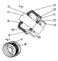
- Fig. 1 is a cable 1, in the electrical conductor. 2 are guided, in the central bore of a cone part 12 led.
- the cone part 12 has in the axial direction 13 of the Cone divided cone segments 9, which in that End portion of the cone part 12 with the larger Outer diameter in cylinder segments 14 pass over. In that End portion of the cone part 12 with smaller Outer diameter are the cone segments 9 via a Sealing lip 11 connected together.
- the connection takes place on both chemical and mechanical Way in which in an injection mold in two steps different materials are injected.
- Axial direction 13 of the cone part seen on both sides is one with a corrugation 6 and a captive 7 (see Fig. 3) provided housing union nut 5 and a Housing base 4 is arranged.
- Both parts have one each self-locking thread 3.16, which connects the allows both parts.
- the housing base 4 can further provided with a coupling plug-in device 15 be or as a connection to a machine housing (not drawn) and points in the area of Thread 3 on the inside a conical inward standing extension 17 (see Fig. 2).
Description
- Fig. 1
- eine axonometrische Ansicht einer erfindungsgemäßen Kabelklemme in aufgeschraubtem Zustand
- Fig. 2
- eine Schnittansicht einer erfindungsgemäßen Kabel klemme
- Fig. 3
- eine axonometrische Ansicht der Gehäuseüberwurfmutter
Claims (4)
- Kabelklemme zur wasserdichten Zug- und Verdrehsicherung von elektrischen Kabeln, mit einem mindestens aus einer Gehäuseüberwurfmutter (5) und einem Gehäusegrundteil (4), welche beide mit Kabeldurchführöffnungen versehen sind, aufgebauten Gehäuse, wobei Gehäuseüberwurfmutter (5) und Gehäusegrundteil (4) verschraubbar (3,16) miteinander verbindbar sind und wobei innerhalb des verschraubten Gehäuses ein flexibler, eine zentrische Bohrung zur Kabelführung aufweisender Konusteil (12) mit einer im wesentlichen kegelmantelförmigen Außenfläche angeordnet ist, wobei die Außenfläche durch Verschrauben der beiden Gehäuseteile (4,5) durch entsprechende am Gehäusegrundteil (4) angeordnete, kegelmantelförmige Fortsätze (17) zusammengedrückt wird und der Konusteil (12) dadurch gegen den Kabelmantel des in der zentrischen Bohrung geführten Kabels (1) pressbar ist, wobei der Konusteil (12) mehrere, in Achsrichtung (13) des Kegels unterteilte Kegelsegmente (9) aufweist, und zwischen den einzelnen Kegelsegmenten Freiräume vorhanden sind, dadurch gekennzeichnet, daß die Kegelsegmente (9) am den kleineren Außendurchmesser aufweisenden Ende des Konusteiles (12) über eine eine zentrische Bohrung aufweisende Dichtlippe (11) miteinander verbunden sind und die Kegelsegmente (9) und die Dichtlippe (11) aus Materialien unterschiedlicher Härte gefertigt sind, wobei die Kegelsegmente aus dem festeren und härterem Material gefertigt sind.
- Sicherungselement nach Anspruch 1 , dadurch gekennzeichnet, daß die Kegelsegmente (9) an dem den größeren Außendurchmesser aufweisenden Ende des Konusteiles (12) in einen Abschnitt mit einer zylindermantelförmigen Außenfläche übergehen.
- Sicherungselement nach Anspruch 1 und 2, dadurch gekennzeichnet, daß die Kegelsegmente (9) aus thermoplastischem Kunststoff, vorzugsweise verstärktem Polypropylen gefertigt sind.
- Sicherungselement nach einem der Ansprüche 1 bis 3, dadurch gekennzeichnet, daß die Dichtlippe (11) aus thermoplastischem Elastomer gefertigt ist.
Priority Applications (1)
| Application Number | Priority Date | Filing Date | Title |
|---|---|---|---|
| AT99890357T ATE231656T1 (de) | 1998-11-11 | 1999-11-08 | Kabelklemme |
Applications Claiming Priority (2)
| Application Number | Priority Date | Filing Date | Title |
|---|---|---|---|
| AT1807798 | 1998-11-11 | ||
| AT1807798 | 1998-11-11 |
Publications (3)
| Publication Number | Publication Date |
|---|---|
| EP1017137A2 EP1017137A2 (de) | 2000-07-05 |
| EP1017137A3 EP1017137A3 (de) | 2001-02-07 |
| EP1017137B1 true EP1017137B1 (de) | 2003-01-22 |
Family
ID=3660959
Family Applications (1)
| Application Number | Title | Priority Date | Filing Date |
|---|---|---|---|
| EP99890357A Expired - Lifetime EP1017137B1 (de) | 1998-11-11 | 1999-11-08 | Kabelklemme |
Country Status (4)
| Country | Link |
|---|---|
| EP (1) | EP1017137B1 (de) |
| AT (1) | ATE231656T1 (de) |
| DE (1) | DE59904087D1 (de) |
| ES (1) | ES2190641T3 (de) |
Families Citing this family (9)
| Publication number | Priority date | Publication date | Assignee | Title |
|---|---|---|---|---|
| AT9304U1 (de) | 2006-06-13 | 2007-07-15 | Pc Electric Gmbh | Leiteranschlussklemme und elektrische steckvorrichtung |
| EP2353211B1 (de) * | 2008-11-03 | 2016-04-20 | PN Development APS | Kabelverbindungsschutz |
| US7641503B1 (en) | 2008-12-15 | 2010-01-05 | Sony Ericsson Mobile Communications Ab | Cable strain reliever |
| WO2012107358A1 (de) * | 2011-02-07 | 2012-08-16 | Hirschmann Automotive Gmbh | Steckverbinder mit zugentlastung für photovoltaikboxen |
| GB2527084A (en) * | 2014-06-11 | 2015-12-16 | Ibm | Cable securing apparatus and method of securing a cable |
| CN105006777B (zh) * | 2015-06-05 | 2017-09-08 | 合肥华凌股份有限公司 | 线束的固定结构及家用电器 |
| KR20180085930A (ko) | 2017-01-20 | 2018-07-30 | 삼성전자주식회사 | 케이블 방수 장치 |
| JP7022335B2 (ja) * | 2018-05-16 | 2022-02-18 | 住友電装株式会社 | コネクタ |
| JP6922838B2 (ja) * | 2018-05-16 | 2021-08-18 | 住友電装株式会社 | コネクタ |
Citations (1)
| Publication number | Priority date | Publication date | Assignee | Title |
|---|---|---|---|---|
| WO1996013080A2 (en) * | 1994-10-25 | 1996-05-02 | Raychem Corporation | Connector for elongate cable |
Family Cites Families (5)
| Publication number | Priority date | Publication date | Assignee | Title |
|---|---|---|---|---|
| NL287732A (de) * | 1962-01-17 | |||
| DE2022879C3 (de) * | 1970-05-11 | 1979-08-23 | Amp Inc., Harrisburg, Pa. (V.St.A.) | Aus heißschrumpfbarem Material geformte, allgemein rohrförmige Kabeldurchführung |
| US4306698A (en) * | 1980-10-16 | 1981-12-22 | General Electric Company | Cable stress/strain relief |
| DE3604214C2 (de) * | 1986-02-11 | 1995-03-16 | Hermann Holzmann | Kabelverschraubung |
| US5410104A (en) * | 1993-04-30 | 1995-04-25 | Arlington Industries Inc. | Low profile strain relief cord grip fitting |
-
1999
- 1999-11-08 DE DE59904087T patent/DE59904087D1/de not_active Expired - Lifetime
- 1999-11-08 EP EP99890357A patent/EP1017137B1/de not_active Expired - Lifetime
- 1999-11-08 AT AT99890357T patent/ATE231656T1/de active
- 1999-11-08 ES ES99890357T patent/ES2190641T3/es not_active Expired - Lifetime
Patent Citations (3)
| Publication number | Priority date | Publication date | Assignee | Title |
|---|---|---|---|---|
| WO1996013080A2 (en) * | 1994-10-25 | 1996-05-02 | Raychem Corporation | Connector for elongate cable |
| EP0788671A2 (de) * | 1994-10-25 | 1997-08-13 | Raychem Corporation | Verbinder für länglichen kabeln |
| EP1020960A2 (de) * | 1994-10-25 | 2000-07-19 | TYCO Electronics Corporation | Dischtungsanordnung für Steckverbinder |
Also Published As
| Publication number | Publication date |
|---|---|
| DE59904087D1 (de) | 2003-02-27 |
| ES2190641T3 (es) | 2003-08-01 |
| EP1017137A3 (de) | 2001-02-07 |
| ATE231656T1 (de) | 2003-02-15 |
| EP1017137A2 (de) | 2000-07-05 |
Similar Documents
| Publication | Publication Date | Title |
|---|---|---|
| EP2299547B1 (de) | Steckverbindergehaeuse mit integrierter Kabelklemmung | |
| DE102009042678B3 (de) | Kabelklemmung mit einem Klemmelement | |
| DE10220108B4 (de) | Kontaktelement mit einem Anschluss für Litzenleiter | |
| EP1332313B1 (de) | Anschlussstück für flexible kunststoffleitungen mit sensoranordnung | |
| EP1017137B1 (de) | Kabelklemme | |
| DE2039953B2 (de) | Verbindungsstück für ein Koaxialkabel | |
| EP1332311A2 (de) | Anschlussstück für flexible kunststoffleitungen | |
| DE3010987A1 (de) | Verbindungsbaugruppe fuer eine elektrische leitung | |
| AT409049B (de) | Kabelklemme | |
| EP1261074B1 (de) | Wasserdichte Kabelzugentlastung | |
| EP3704774B1 (de) | Bauteil mit einem gehäuse, einem kabelstrang und eine zugentlastung | |
| EP0911936A1 (de) | Kabelendverschluss oder Kabelmuffe mit geometrischer Feldsteuerung | |
| DE102016214578A1 (de) | Kabelverschraubung und Steckverbinder mit einer Kabelverschraubung | |
| DE202019101084U1 (de) | Anschlusseinrichtung | |
| WO1998049752A1 (de) | Schirmklemmanschluss | |
| DE4039430C2 (de) | ||
| DE2635613C3 (de) | Durchführung für Leitungen, vorzugsweise elektrische Leitungen | |
| EP1303020A2 (de) | Elektrische Verkabelung mit Zugentlastung | |
| DE19717628A1 (de) | Schirmanschlußsystem bzw. Schirmadapter insbesondere für Kabelsätze | |
| DE3409958C2 (de) | ||
| EP0636283A1 (de) | Stopfen zum elektrisch dichten verschliessen einer steckbuchse. | |
| DE8228160U1 (de) | Kabeleinführung | |
| DE19501540C1 (de) | Maschinenbaustecker | |
| DE1490159A1 (de) | Elektrische Steckerverbindung | |
| DE202007008293U1 (de) | Vorrichtung zum Befestigen von elektrischen Leitungen |
Legal Events
| Date | Code | Title | Description |
|---|---|---|---|
| PUAI | Public reference made under article 153(3) epc to a published international application that has entered the european phase |
Free format text: ORIGINAL CODE: 0009012 |
|
| AK | Designated contracting states |
Kind code of ref document: A2 Designated state(s): AT BE CH CY DE DK ES FI FR GB GR IE IT LI LU MC NL PT SE |
|
| AX | Request for extension of the european patent |
Free format text: AL;LT;LV;MK;RO;SI |
|
| PUAL | Search report despatched |
Free format text: ORIGINAL CODE: 0009013 |
|
| AK | Designated contracting states |
Kind code of ref document: A3 Designated state(s): AT BE CH CY DE DK ES FI FR GB GR IE IT LI LU MC NL PT SE |
|
| AX | Request for extension of the european patent |
Free format text: AL;LT;LV;MK;RO;SI |
|
| RIC1 | Information provided on ipc code assigned before grant |
Free format text: 7H 01R 13/58 A, 7H 01R 13/52 B, 7H 01R 13/59 B, 7H 02G 3/06 B, 7H 01B 17/58 B |
|
| 17P | Request for examination filed |
Effective date: 20010430 |
|
| 17Q | First examination report despatched |
Effective date: 20010709 |
|
| AKX | Designation fees paid |
Free format text: AT BE CH CY DE DK ES FI FR GB GR IE IT LI LU MC NL PT SE |
|
| GRAH | Despatch of communication of intention to grant a patent |
Free format text: ORIGINAL CODE: EPIDOS IGRA |
|
| GRAH | Despatch of communication of intention to grant a patent |
Free format text: ORIGINAL CODE: EPIDOS IGRA |
|
| GRAA | (expected) grant |
Free format text: ORIGINAL CODE: 0009210 |
|
| AK | Designated contracting states |
Kind code of ref document: B1 Designated state(s): AT BE CH CY DE DK ES FI FR GB GR IE IT LI LU MC NL PT SE |
|
| PG25 | Lapsed in a contracting state [announced via postgrant information from national office to epo] |
Ref country code: GR Free format text: LAPSE BECAUSE OF FAILURE TO SUBMIT A TRANSLATION OF THE DESCRIPTION OR TO PAY THE FEE WITHIN THE PRESCRIBED TIME-LIMIT Effective date: 20030122 |
|
| REG | Reference to a national code |
Ref country code: GB Ref legal event code: FG4D Free format text: NOT ENGLISH |
|
| REG | Reference to a national code |
Ref country code: CH Ref legal event code: EP |
|
| REG | Reference to a national code |
Ref country code: IE Ref legal event code: FG4D Free format text: GERMAN |
|
| REF | Corresponds to: |
Ref document number: 59904087 Country of ref document: DE Date of ref document: 20030227 Kind code of ref document: P |
|
| REG | Reference to a national code |
Ref country code: CH Ref legal event code: NV Representative=s name: PATENTANWAELTE SCHAAD, BALASS, MENZL & PARTNER AG |
|
| PG25 | Lapsed in a contracting state [announced via postgrant information from national office to epo] |
Ref country code: DK Free format text: LAPSE BECAUSE OF FAILURE TO SUBMIT A TRANSLATION OF THE DESCRIPTION OR TO PAY THE FEE WITHIN THE PRESCRIBED TIME-LIMIT Effective date: 20030422 |
|
| GBT | Gb: translation of ep patent filed (gb section 77(6)(a)/1977) |
Effective date: 20030425 |
|
| REG | Reference to a national code |
Ref country code: ES Ref legal event code: FG2A Ref document number: 2190641 Country of ref document: ES Kind code of ref document: T3 |
|
| ET | Fr: translation filed | ||
| PGFP | Annual fee paid to national office [announced via postgrant information from national office to epo] |
Ref country code: IE Payment date: 20031022 Year of fee payment: 5 |
|
| PGFP | Annual fee paid to national office [announced via postgrant information from national office to epo] |
Ref country code: LU Payment date: 20031029 Year of fee payment: 5 |
|
| PGFP | Annual fee paid to national office [announced via postgrant information from national office to epo] |
Ref country code: MC Payment date: 20031104 Year of fee payment: 5 |
|
| PG25 | Lapsed in a contracting state [announced via postgrant information from national office to epo] |
Ref country code: CY Free format text: LAPSE BECAUSE OF FAILURE TO SUBMIT A TRANSLATION OF THE DESCRIPTION OR TO PAY THE FEE WITHIN THE PRESCRIBED TIME-LIMIT Effective date: 20031108 |
|
| PGFP | Annual fee paid to national office [announced via postgrant information from national office to epo] |
Ref country code: CH Payment date: 20031127 Year of fee payment: 5 |
|
| PLBE | No opposition filed within time limit |
Free format text: ORIGINAL CODE: 0009261 |
|
| STAA | Information on the status of an ep patent application or granted ep patent |
Free format text: STATUS: NO OPPOSITION FILED WITHIN TIME LIMIT |
|
| 26N | No opposition filed |
Effective date: 20031023 |
|
| PG25 | Lapsed in a contracting state [announced via postgrant information from national office to epo] |
Ref country code: LU Free format text: LAPSE BECAUSE OF NON-PAYMENT OF DUE FEES Effective date: 20041108 Ref country code: IE Free format text: LAPSE BECAUSE OF NON-PAYMENT OF DUE FEES Effective date: 20041108 |
|
| PG25 | Lapsed in a contracting state [announced via postgrant information from national office to epo] |
Ref country code: MC Free format text: LAPSE BECAUSE OF NON-PAYMENT OF DUE FEES Effective date: 20041130 Ref country code: LI Free format text: LAPSE BECAUSE OF NON-PAYMENT OF DUE FEES Effective date: 20041130 Ref country code: CH Free format text: LAPSE BECAUSE OF NON-PAYMENT OF DUE FEES Effective date: 20041130 |
|
| REG | Reference to a national code |
Ref country code: CH Ref legal event code: PL |
|
| PGFP | Annual fee paid to national office [announced via postgrant information from national office to epo] |
Ref country code: FR Payment date: 20050831 Year of fee payment: 7 |
|
| PGFP | Annual fee paid to national office [announced via postgrant information from national office to epo] |
Ref country code: PT Payment date: 20051012 Year of fee payment: 7 |
|
| PGFP | Annual fee paid to national office [announced via postgrant information from national office to epo] |
Ref country code: FI Payment date: 20051103 Year of fee payment: 7 |
|
| REG | Reference to a national code |
Ref country code: IE Ref legal event code: MM4A |
|
| PG25 | Lapsed in a contracting state [announced via postgrant information from national office to epo] |
Ref country code: FI Free format text: LAPSE BECAUSE OF NON-PAYMENT OF DUE FEES Effective date: 20061108 |
|
| PGFP | Annual fee paid to national office [announced via postgrant information from national office to epo] |
Ref country code: BE Payment date: 20061122 Year of fee payment: 8 |
|
| PG25 | Lapsed in a contracting state [announced via postgrant information from national office to epo] |
Ref country code: PT Free format text: LAPSE BECAUSE OF NON-PAYMENT OF DUE FEES Effective date: 20070508 |
|
| REG | Reference to a national code |
Ref country code: PT Ref legal event code: MM4A Free format text: LAPSE DUE TO NON-PAYMENT OF FEES Effective date: 20070508 |
|
| REG | Reference to a national code |
Ref country code: FR Ref legal event code: ST Effective date: 20070731 |
|
| PG25 | Lapsed in a contracting state [announced via postgrant information from national office to epo] |
Ref country code: FR Free format text: LAPSE BECAUSE OF NON-PAYMENT OF DUE FEES Effective date: 20061130 |
|
| BERE | Be: lapsed |
Owner name: *PC ELECTRIC G.M.B.H. Effective date: 20071130 |
|
| PG25 | Lapsed in a contracting state [announced via postgrant information from national office to epo] |
Ref country code: BE Free format text: LAPSE BECAUSE OF NON-PAYMENT OF DUE FEES Effective date: 20071130 |
|
| PGFP | Annual fee paid to national office [announced via postgrant information from national office to epo] |
Ref country code: NL Payment date: 20101129 Year of fee payment: 12 |
|
| PGFP | Annual fee paid to national office [announced via postgrant information from national office to epo] |
Ref country code: IT Payment date: 20101126 Year of fee payment: 12 |
|
| PGFP | Annual fee paid to national office [announced via postgrant information from national office to epo] |
Ref country code: ES Payment date: 20101117 Year of fee payment: 12 |
|
| REG | Reference to a national code |
Ref country code: NL Ref legal event code: V1 Effective date: 20120601 |
|
| PG25 | Lapsed in a contracting state [announced via postgrant information from national office to epo] |
Ref country code: NL Free format text: LAPSE BECAUSE OF NON-PAYMENT OF DUE FEES Effective date: 20120601 |
|
| PG25 | Lapsed in a contracting state [announced via postgrant information from national office to epo] |
Ref country code: IT Free format text: LAPSE BECAUSE OF NON-PAYMENT OF DUE FEES Effective date: 20111108 |
|
| REG | Reference to a national code |
Ref country code: ES Ref legal event code: FD2A Effective date: 20130604 |
|
| PG25 | Lapsed in a contracting state [announced via postgrant information from national office to epo] |
Ref country code: ES Free format text: LAPSE BECAUSE OF NON-PAYMENT OF DUE FEES Effective date: 20111109 |
|
| PGFP | Annual fee paid to national office [announced via postgrant information from national office to epo] |
Ref country code: SE Payment date: 20181114 Year of fee payment: 20 Ref country code: DE Payment date: 20181126 Year of fee payment: 20 Ref country code: AT Payment date: 20181127 Year of fee payment: 20 |
|
| PGFP | Annual fee paid to national office [announced via postgrant information from national office to epo] |
Ref country code: GB Payment date: 20181130 Year of fee payment: 20 |
|
| REG | Reference to a national code |
Ref country code: DE Ref legal event code: R071 Ref document number: 59904087 Country of ref document: DE |
|
| REG | Reference to a national code |
Ref country code: GB Ref legal event code: PE20 Expiry date: 20191107 |
|
| REG | Reference to a national code |
Ref country code: AT Ref legal event code: MK07 Ref document number: 231656 Country of ref document: AT Kind code of ref document: T Effective date: 20191108 |
|
| PG25 | Lapsed in a contracting state [announced via postgrant information from national office to epo] |
Ref country code: GB Free format text: LAPSE BECAUSE OF EXPIRATION OF PROTECTION Effective date: 20191107 |
|
| REG | Reference to a national code |
Ref country code: SE Ref legal event code: EUG |