EP1016825A1 - Verbrennungsverfahren und Verwendung zur Erzeugung von Glas und Metall - Google Patents
Verbrennungsverfahren und Verwendung zur Erzeugung von Glas und Metall Download PDFInfo
- Publication number
- EP1016825A1 EP1016825A1 EP99402850A EP99402850A EP1016825A1 EP 1016825 A1 EP1016825 A1 EP 1016825A1 EP 99402850 A EP99402850 A EP 99402850A EP 99402850 A EP99402850 A EP 99402850A EP 1016825 A1 EP1016825 A1 EP 1016825A1
- Authority
- EP
- European Patent Office
- Prior art keywords
- passage
- oxidizer
- fuel
- supply
- injector
- Prior art date
- Legal status (The legal status is an assumption and is not a legal conclusion. Google has not performed a legal analysis and makes no representation as to the accuracy of the status listed.)
- Granted
Links
Images

Classifications
-
- F—MECHANICAL ENGINEERING; LIGHTING; HEATING; WEAPONS; BLASTING
- F23—COMBUSTION APPARATUS; COMBUSTION PROCESSES
- F23D—BURNERS
- F23D14/00—Burners for combustion of a gas, e.g. of a gas stored under pressure as a liquid
- F23D14/20—Non-premix gas burners, i.e. in which gaseous fuel is mixed with combustion air on arrival at the combustion zone
- F23D14/22—Non-premix gas burners, i.e. in which gaseous fuel is mixed with combustion air on arrival at the combustion zone with separate air and gas feed ducts, e.g. with ducts running parallel or crossing each other
-
- C—CHEMISTRY; METALLURGY
- C03—GLASS; MINERAL OR SLAG WOOL
- C03B—MANUFACTURE, SHAPING, OR SUPPLEMENTARY PROCESSES
- C03B5/00—Melting in furnaces; Furnaces so far as specially adapted for glass manufacture
- C03B5/16—Special features of the melting process; Auxiliary means specially adapted for glass-melting furnaces
- C03B5/235—Heating the glass
- C03B5/2353—Heating the glass by combustion with pure oxygen or oxygen-enriched air, e.g. using oxy-fuel burners or oxygen lances
-
- F—MECHANICAL ENGINEERING; LIGHTING; HEATING; WEAPONS; BLASTING
- F23—COMBUSTION APPARATUS; COMBUSTION PROCESSES
- F23D—BURNERS
- F23D14/00—Burners for combustion of a gas, e.g. of a gas stored under pressure as a liquid
- F23D14/32—Burners for combustion of a gas, e.g. of a gas stored under pressure as a liquid using a mixture of gaseous fuel and pure oxygen or oxygen-enriched air
-
- Y—GENERAL TAGGING OF NEW TECHNOLOGICAL DEVELOPMENTS; GENERAL TAGGING OF CROSS-SECTIONAL TECHNOLOGIES SPANNING OVER SEVERAL SECTIONS OF THE IPC; TECHNICAL SUBJECTS COVERED BY FORMER USPC CROSS-REFERENCE ART COLLECTIONS [XRACs] AND DIGESTS
- Y02—TECHNOLOGIES OR APPLICATIONS FOR MITIGATION OR ADAPTATION AGAINST CLIMATE CHANGE
- Y02P—CLIMATE CHANGE MITIGATION TECHNOLOGIES IN THE PRODUCTION OR PROCESSING OF GOODS
- Y02P40/00—Technologies relating to the processing of minerals
- Y02P40/50—Glass production, e.g. reusing waste heat during processing or shaping
Definitions
- the subject of the present invention is a method of combustion of a fuel in a burner of the type comprising an injector, which injector has at least a first interior passage for the supply of oxidant, a intermediate fuel supply passage externally surrounding the first oxidizer supply passage, and a second exterior passage of oxidant intake externally surrounding the intake passage of combustible.
- the invention applies in particular to the supply of heat in the materials development processes.
- burners of the above type are used with, for example, methane as fuel and oxygen as an oxidizer.
- glass is generally transferred between two successive stages of the process by through channels or "feeders".
- feeders In such a channel, the glass located at proximity to channel walls tends to cool much faster than glass further from these walls. Consequently, it is desirable to be able to reheat the periphery of the glass without heating the heart of the latter, to maintain a substantially homogeneous temperature profile in the sections of the molten material.
- burners of the aforementioned type are arranged in the walls of these transfer channels.
- the combustion processes known using burners of the above type do not always allow to adjust the length of the flames produced to adequately heat the sections of the channeled molten material.
- the known combustion methods do not make it possible to comply with the constraints concerning the concentrations of the oxidizing species CO and O 2 , linked to the length of the flame, at the outlet of the burners arranged near the baths of molten materials in the processes. metal working.
- the object of the invention is to solve these problems by providing a combustion method for a burner of the aforementioned type making it possible to finely adjust the length of the flame and the concentrations of chemical species in it, in particular CO and O 2 .
- the invention relates to a method of combustion of a fuel in a burner of the aforementioned type, characterized in that the fuel feed passage so that the fuel exit speed of this passage is between approximately 1 and 15 m / s.
- the invention also relates to the use of a method such as defined above to allow, by modifying the proportion of the total oxidant flow passing through the first oxidizer supply passage, an adjustment of the length of a heating flame of a molten glass transfer channel during glass making.
- the subject of the invention is the use of a method such as defined above to allow, by modifying the proportion of the total oxidant flow passing through the first oxidizer supply passage, an adjustment of the oxidizing power of a heating flame produced during the preparation of metal.
- FIG. 1 schematically represents a burner 1 comprising an injector 2 inserted in the axisymmetric orifice or opening 3 of a block 4 in refractory material.
- This block 4 is itself mounted in the wall of an oven or, for example, of a "feeder” from a glass making installation.
- the injector 2 essentially comprises three coaxial tubes 5, 6 and 7 of axis X-X and circular sections.
- the inner tube 5 internally defines a first interior passage 8 of oxidizer supply.
- the intermediate tube 6 surrounds externally the tube 5 and defines therewith an intermediate passage 9 for supplying fuel.
- the outer tube 7 externally surrounds the intermediate tube 6 and defines with it a second external passage 10 for supplying oxidant.
- a source 12 of oxidizer for example oxygen (O 2 ) of purity greater than 80%, is connected via valves 13 and 14 respectively to the upstream ends (on the left in FIG. 1) of the passages 8 and 10 of oxidizer supply.
- O 2 oxygen
- a fuel source 15 for example methane gas (CH 4 ), is connected via a valve 16 to the upstream end (on the left in FIG. 1) of the passage 9 for supplying the fuel.
- CH 4 methane gas
- downstream ends of the tubes 5 to 7 are substantially aligned transversely to the X-X axis, thus delimiting a downstream or outlet face 17 of the injector 2.
- downstream ends of the tubes 5 to 7 can be offset along the axis X-X and one of the tubes 5 to 7 can be offset with respect to the other tubes.
- the shutter 3 comprises an upstream part 18 of circular section and a downstream part 19 of generally frustoconical shape diverging downstream.
- the downstream end of the injector 2 is inserted into the upstream part 18 of the outlet 3.
- the downstream face 17 of the injector 2 is located at the junction of the parts upstream 18 and downstream 19 of the opening 3.
- the opening 3 and the injector 2 are coaxial.
- a flame is formed at the outlet of the injector 2 by the combustion of CH 4 in the presence of O 2 .
- O 2 is consumed to form CO then CO 2 and water (H 2 O) from CH 4 .
- the axial concentration (along axis XX) of O 2 gradually decreases from the outlet of the injector 2 towards the downstream end of the flame formed, while the concentration of CO 2 increases.
- the CO concentration increases and then decreases from the outlet of injector 2 to the downstream end of the flame.
- the axial concentration of CO has a general peak profile.
- Valves 13 and 14 allow the quantity to be varied of oxygen passing respectively in the passages 8 and 10 of supply of oxidizer, and therefore regulate the oxygen speeds at the outlet of these passages 8 and 10. Valves 13 and 14 also allow adjustment of the distribution total oxygen flow between first pass 8 and second pass 10 oxidizer supply. Valve 16 allows the quantity of methane to be varied passing through the fuel supply passage 9 and therefore regulating the speed of methane leaving this passage 9.
- valve 16 is adjusted so that the speed of fuel at the outlet of passage 9, about 11 m / s.
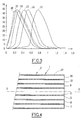
- Figure 2 is a diagram illustrating the adjustment possibilities characteristics of the flame thus offered.
- the abscissa axis represents the proportion P of O 2 injected in the interior passage 8 compared to the total O 2 injected in the passages 8 and 10.
- the ordinate axis represents the proportion of CO by compared to all the species present in the axis XX of the flame 0.635 m from the outlet of the injector 2.
- a first measurement curve corresponds to a combustion process implemented with a burner 1 whose inner tube 5 has an internal diameter of approximately 2 mm and the intermediate tube 6 has an internal diameter of approximately 15 mm .
- the power of the burner 1 is approximately 60 kW, which corresponds approximately to the injection of 6 Nm 3 / h of CH 4 and to the total injection of 12 Nm 3 / h of O 2 .
- This first curve decreases relatively pronounced when P varies from about 0 to 15%. This decrease corresponds to the decreasing part of the general peak profile of the axial CO concentration in the flame.
- the speed of the O 2 at the outlet of the internal passage 8 is approximately 212 m / s and 33 m / s when P is respectively approximately 20% and 3.10%.
- the ratio R between the speed of O 2 leaving the internal passage 8 and the speed of CH 4 leaving the passage 9 is approximately 19.3 and 3 when P is respectively 20% and 3.1%.
- the second measurement curve in solid line, corresponds to a process which differs from that of the first curve in that it is implemented on a burner 1 whose inner tube 5 has an inner diameter about 3.5 mm.
- This second curve in strong lines has a peak profile, with, of a share, a part increasing relatively strongly when P varies between O and approximately 10% and, on the other hand, a part decreasing relatively strongly when P varies between around 10 and 20%.
- the increasing and decreasing parts of the second curve correspond respectively to the increasing and decreasing parts of the general peak profile of the axial CO concentration in the flame produced.
- the ratio R has a value of around 3 when P is 10% and about 6 when P is 20%.
- the length of the flame produced decreases when P varies from 0 to around 20 %. It is therefore possible to adjust the length of the flame produced from finer than in the case of the first dotted curve.
- the third measurement curve in dashed line, corresponds to a process combustion, implemented in the burner 1 of the first curve, and where the speed of methane at the outlet of passage 9 is approximately 75 m / s.
- the third curve is substantially a horizontal line.
- P 0%
- the CO proportion is around 2%.
- the third curve corresponds so at the tail of the general profile in peak of the axial concentration in CO in the flame produced.
- the possibility of varying the proportion of CO at the chosen measurement point and therefore the length of the flame is appreciably nothing.
- FIG. 3 illustrates, for the method corresponding to the curve in strong feature of Figure 2, the change in the relative proportion of CO compared to to the other species present in the axis of the flame X-X for different proportions P for injecting oxygen between the interior 8 and exterior 10 passages.
- the abscissa represents the distance from the measurement point to the output of injector 2.
- the measurement curves 21 to 26 correspond respectively to the case where the proportion P of oxygen injected in passage 8 relative to the total oxygen injected is approximately 0%, 10%, 12.5%, 15%, 17.5% and 20%.
- Each of the curves 21 to 26 has a peak profile.
- the speed of fuel outlet from intermediate passage 9 must be between approximately 1 and 15 m / s, and preferably between about 5 and 15 m / s, and the gear ratio R must be between 3 and 20 and preferably between 3 and 10.
- the output speed oxidizer of the second pass should be between about 0.1 and 50 m / s and preferably between about 1 and 5 m / s.
- Such a combustion process can be used in particular in materials development processes.
- this combustion process is particularly suitable for the processes for preparing metals.
- the method is preferably implemented works on a burner 1, such as that of FIG. 4, the injector 2 of which comprises a fourth tube 26 externally surrounding the tube 7 so as to delimit with the tube 7 a passage 27 for channeling an external air stream.
- This combustion process is also particularly suitable to heat the molten glass when it is channeled into “feeders” in the glass making processes. Indeed, this process will allow for example to obtain a sufficiently short flame at the outlet of the injector 2, by playing on the proportion P, so as not to heat the core of the molten glass channeled by a "Feeder"
Landscapes
- Engineering & Computer Science (AREA)
- Chemical & Material Sciences (AREA)
- Combustion & Propulsion (AREA)
- Mechanical Engineering (AREA)
- General Engineering & Computer Science (AREA)
- Materials Engineering (AREA)
- Organic Chemistry (AREA)
- Pre-Mixing And Non-Premixing Gas Burner (AREA)
- Gas Burners (AREA)
- Glass Melting And Manufacturing (AREA)
- Manufacture, Treatment Of Glass Fibers (AREA)
- Furnace Details (AREA)
Applications Claiming Priority (2)
| Application Number | Priority Date | Filing Date | Title |
|---|---|---|---|
| FR9816634A FR2788110B1 (fr) | 1998-12-30 | 1998-12-30 | Procede de combustion et ses utilisations pour l'elaboration de verre et de metal |
| FR9816634 | 1998-12-30 |
Publications (2)
| Publication Number | Publication Date |
|---|---|
| EP1016825A1 true EP1016825A1 (de) | 2000-07-05 |
| EP1016825B1 EP1016825B1 (de) | 2003-08-27 |
Family
ID=9534678
Family Applications (1)
| Application Number | Title | Priority Date | Filing Date |
|---|---|---|---|
| EP99402850A Expired - Lifetime EP1016825B1 (de) | 1998-12-30 | 1999-11-17 | Verbrennungsverfahren und dessen Verwendung zur Erzeugung von Glas und Metall |
Country Status (7)
| Country | Link |
|---|---|
| US (1) | US6190158B1 (de) |
| EP (1) | EP1016825B1 (de) |
| JP (1) | JP2000193215A (de) |
| CN (2) | CN101210676B (de) |
| DE (1) | DE69910725T2 (de) |
| ES (1) | ES2207151T3 (de) |
| FR (1) | FR2788110B1 (de) |
Cited By (6)
| Publication number | Priority date | Publication date | Assignee | Title |
|---|---|---|---|---|
| WO2009010697A2 (fr) | 2007-07-10 | 2009-01-22 | L'air Liquide Societe Anonyme Pour L'etude Et L'exploitation Des Procedes Georges Claude | Four et procede oxy-combustible pour la fusion de matieres vitrifiables |
| US7775791B2 (en) | 2008-02-25 | 2010-08-17 | General Electric Company | Method and apparatus for staged combustion of air and fuel |
| CN109556112A (zh) * | 2018-12-10 | 2019-04-02 | 淮海工学院 | 一种基于化学计量数配比的同心交替伴流气体燃烧器 |
| CN109611911A (zh) * | 2018-11-23 | 2019-04-12 | 吴利琴 | 一种高安全性的可升降集成灶 |
| EP3671038A1 (de) | 2018-12-21 | 2020-06-24 | L'air Liquide, Societe Anonyme Pour L'etude Et L'exploitation Des Procedes Georges Claude | Anordnung für die injektion von gasförmigem brennmittel |
| CN112745012A (zh) * | 2019-10-29 | 2021-05-04 | 霍尼韦尔国际公司 | 燃料气体和氧气燃烧器 |
Families Citing this family (27)
| Publication number | Priority date | Publication date | Assignee | Title |
|---|---|---|---|---|
| FR2814796B1 (fr) * | 2000-10-03 | 2003-08-29 | Air Liquide | Bruleur tri-tubes pour fours notamment a verre et a metaux, et procede d'injection de combustible et de carburant par un tel bruleur |
| KR100414668B1 (ko) * | 2001-07-21 | 2004-01-07 | 삼성전자주식회사 | 화염가수분해증착 공정용 버너의 화염 안정화 장치 |
| US6752620B2 (en) * | 2002-01-31 | 2004-06-22 | Air Products And Chemicals, Inc. | Large scale vortex devices for improved burner operation |
| US20070048679A1 (en) * | 2003-01-29 | 2007-03-01 | Joshi Mahendra L | Fuel dilution for reducing NOx production |
| CA2487146C (en) * | 2003-11-14 | 2009-01-20 | Air Products And Chemicals, Inc. | Fuel staging process for low nox operations |
| WO2005095857A1 (de) * | 2004-03-23 | 2005-10-13 | Software & Technologie Glas Gmbh (Stg) | Gasinjektor |
| FR2892497B1 (fr) * | 2005-10-24 | 2008-07-04 | Air Liquide | Procede de combustion mixte dans un four a regenerateurs |
| US20070231761A1 (en) * | 2006-04-03 | 2007-10-04 | Lee Rosen | Integration of oxy-fuel and air-fuel combustion |
| US7717701B2 (en) * | 2006-10-24 | 2010-05-18 | Air Products And Chemicals, Inc. | Pulverized solid fuel burner |
| DE102007019830B3 (de) * | 2007-04-25 | 2008-07-31 | Uhde Gmbh | Primärreformer mit brennerzuführenden Sekundäreinlasskanälen |
| FR2915989B1 (fr) * | 2007-05-10 | 2011-05-20 | Saint Gobain Emballage | Injecteur mixte a bas nox |
| DE102007025051B4 (de) * | 2007-05-29 | 2011-06-01 | Hitachi Power Europe Gmbh | Hüttengasbrenner |
| FR2927409B1 (fr) * | 2008-02-11 | 2013-01-04 | Air Liquide | Procede de chauffage d'un cru mineral dans un four de cuisson de type four tunnel |
| JP5116505B2 (ja) * | 2008-02-21 | 2013-01-09 | 大陽日酸株式会社 | バーナおよびこれを用いる球状化粒子の製造方法 |
| US20100233639A1 (en) * | 2009-03-11 | 2010-09-16 | Richardson Andrew P | Burner for reducing wall wear in a melter |
| US8404018B2 (en) * | 2009-07-06 | 2013-03-26 | Air Products And Chemicals, Inc. | Burner and method for processing oxidizable materials |
| CN103328888B (zh) * | 2011-01-28 | 2015-07-08 | 大阪瓦斯株式会社 | 炉加热用燃烧装置 |
| DE102011015317A1 (de) * | 2011-03-28 | 2012-10-04 | Air Liquide Deutschland Gmbh | Verfahren und Vorrichtung zum Betreiben eines Ofens |
| EA024686B1 (ru) * | 2011-05-31 | 2016-10-31 | Ототек Оюй | Горелочное устройство и горелочный блок |
| WO2015007252A1 (en) | 2013-07-15 | 2015-01-22 | Flammatec, Spol. S R.O. | The way of gas combustion in industrial furnaces and burner for realization of this method |
| CN103528059A (zh) * | 2013-11-12 | 2014-01-22 | 哈尔滨前程科技发展有限公司 | 工业炉窑用多功能分步高氧燃烧器 |
| JP6257422B2 (ja) * | 2014-04-03 | 2018-01-10 | 大阪瓦斯株式会社 | 加熱炉用燃焼装置 |
| JP6102009B2 (ja) * | 2015-02-27 | 2017-03-29 | 大陽日酸株式会社 | 気体燃料バーナ、及び気体燃料バーナによる加熱方法 |
| JP6043393B2 (ja) * | 2015-03-31 | 2016-12-14 | 大陽日酸株式会社 | バーナの火炎形成方法 |
| JP7139298B2 (ja) * | 2019-09-27 | 2022-09-20 | 大陽日酸株式会社 | 高温酸素発生装置及び高温酸素発生方法 |
| WO2021233530A1 (en) | 2020-05-19 | 2021-11-25 | Flammatec, Spol. S R.O. | Method and burner of hydrogen combustion in industrial furnace, especially in a glass furnace or a furnace for metal melting, by means of a multi nozzle burner |
| CN115710081A (zh) * | 2022-11-18 | 2023-02-24 | 虹阳显示(咸阳)科技有限公司 | 一种tft液晶玻璃基板窑炉料山修正装置及方法 |
Citations (3)
| Publication number | Priority date | Publication date | Assignee | Title |
|---|---|---|---|---|
| US4933163A (en) * | 1987-10-16 | 1990-06-12 | Metallgesellschaft Ag | Process of removing hydrogen sulfide from exhaust gas |
| EP0643262A1 (de) * | 1993-09-09 | 1995-03-15 | L'air Liquide, Societe Anonyme Pour L'etude Et L'exploitation Des Procedes Georges Claude | Verbrennungsverfahren |
| EP0763692A2 (de) * | 1995-09-15 | 1997-03-19 | L'air Liquide, Societe Anonyme Pour L'etude Et L'exploitation Des Procedes Georges Claude | Sauerstoff-Brennstoff-Brenner mit koaxialem Auslass von Brennstoff und Oxidationsmittel |
Family Cites Families (5)
| Publication number | Priority date | Publication date | Assignee | Title |
|---|---|---|---|---|
| DE3715453A1 (de) * | 1987-05-08 | 1988-11-24 | Krupp Polysius Ag | Verfahren und brenner zur verfeuerung von brennstoff |
| US5178533A (en) * | 1989-10-04 | 1993-01-12 | Enterprise Generale De Chauffage Industries Pillard | Process for exploiting a burner and burners for a rotary tubular furnance |
| US5209656A (en) * | 1991-08-29 | 1993-05-11 | Praxair Technology, Inc. | Combustion system for high velocity gas injection |
| FR2757844B1 (fr) * | 1996-12-26 | 1999-01-29 | Air Liquide | Procede de fabrication de verre technique et bruleur pour la mise en oeuvre d'un tel procede |
| US5904475A (en) * | 1997-05-08 | 1999-05-18 | Praxair Technology, Inc. | Dual oxidant combustion system |
-
1998
- 1998-12-30 FR FR9816634A patent/FR2788110B1/fr not_active Expired - Fee Related
-
1999
- 1999-11-17 ES ES99402850T patent/ES2207151T3/es not_active Expired - Lifetime
- 1999-11-17 DE DE69910725T patent/DE69910725T2/de not_active Expired - Lifetime
- 1999-11-17 EP EP99402850A patent/EP1016825B1/de not_active Expired - Lifetime
- 1999-12-21 US US09/467,949 patent/US6190158B1/en not_active Expired - Lifetime
- 1999-12-24 JP JP11367507A patent/JP2000193215A/ja active Pending
- 1999-12-28 CN CN2007101419012A patent/CN101210676B/zh not_active Expired - Lifetime
- 1999-12-28 CN CN99127086A patent/CN1258828A/zh active Pending
Patent Citations (3)
| Publication number | Priority date | Publication date | Assignee | Title |
|---|---|---|---|---|
| US4933163A (en) * | 1987-10-16 | 1990-06-12 | Metallgesellschaft Ag | Process of removing hydrogen sulfide from exhaust gas |
| EP0643262A1 (de) * | 1993-09-09 | 1995-03-15 | L'air Liquide, Societe Anonyme Pour L'etude Et L'exploitation Des Procedes Georges Claude | Verbrennungsverfahren |
| EP0763692A2 (de) * | 1995-09-15 | 1997-03-19 | L'air Liquide, Societe Anonyme Pour L'etude Et L'exploitation Des Procedes Georges Claude | Sauerstoff-Brennstoff-Brenner mit koaxialem Auslass von Brennstoff und Oxidationsmittel |
Cited By (8)
| Publication number | Priority date | Publication date | Assignee | Title |
|---|---|---|---|---|
| WO2009010697A2 (fr) | 2007-07-10 | 2009-01-22 | L'air Liquide Societe Anonyme Pour L'etude Et L'exploitation Des Procedes Georges Claude | Four et procede oxy-combustible pour la fusion de matieres vitrifiables |
| US7775791B2 (en) | 2008-02-25 | 2010-08-17 | General Electric Company | Method and apparatus for staged combustion of air and fuel |
| GB2457565B (en) * | 2008-02-25 | 2012-10-03 | Gen Electric | Method and apparatus for staged combustion of air and fuel |
| CN109611911A (zh) * | 2018-11-23 | 2019-04-12 | 吴利琴 | 一种高安全性的可升降集成灶 |
| CN109556112A (zh) * | 2018-12-10 | 2019-04-02 | 淮海工学院 | 一种基于化学计量数配比的同心交替伴流气体燃烧器 |
| EP3671038A1 (de) | 2018-12-21 | 2020-06-24 | L'air Liquide, Societe Anonyme Pour L'etude Et L'exploitation Des Procedes Georges Claude | Anordnung für die injektion von gasförmigem brennmittel |
| WO2020126401A1 (fr) | 2018-12-21 | 2020-06-25 | L'air Liquide, Societe Anonyme Pour L'etude Et L'exploitation Des Procedes Georges Claude | Ensemble et procédé pour l'injection d'un agent de combustion gazeux |
| CN112745012A (zh) * | 2019-10-29 | 2021-05-04 | 霍尼韦尔国际公司 | 燃料气体和氧气燃烧器 |
Also Published As
| Publication number | Publication date |
|---|---|
| FR2788110B1 (fr) | 2001-02-16 |
| EP1016825B1 (de) | 2003-08-27 |
| FR2788110A1 (fr) | 2000-07-07 |
| DE69910725D1 (de) | 2003-10-02 |
| ES2207151T3 (es) | 2004-05-16 |
| JP2000193215A (ja) | 2000-07-14 |
| CN101210676A (zh) | 2008-07-02 |
| US6190158B1 (en) | 2001-02-20 |
| CN101210676B (zh) | 2012-01-18 |
| DE69910725T2 (de) | 2004-07-08 |
| CN1258828A (zh) | 2000-07-05 |
Similar Documents
| Publication | Publication Date | Title |
|---|---|---|
| EP1016825B1 (de) | Verbrennungsverfahren und dessen Verwendung zur Erzeugung von Glas und Metall | |
| EP0674135B1 (de) | Gasbrenner für Industrieöfen | |
| EP1031790B1 (de) | Verbesserungen an Flachflammenbrennern | |
| FR2485692A1 (fr) | Procede et bruleur pour produire une combustion a faible teneur en oxydes d'azote des gaz d'echappement dans un tube radiant | |
| FR2581163A1 (fr) | Bruleur pour flamber des materiaux en acier | |
| FR2823290A1 (fr) | Procede de combustion comportant des injections separees de combustible et d oxydant et ensemble bruleur pour la mise en oeuvre de ce procede | |
| FR2535018A1 (fr) | Bruleur a charbon pulverise | |
| FR2530317A1 (fr) | Procede et dispositif pour la combustion de gaz combustibles avec induction d'air atmospherique | |
| EP0014812B1 (de) | Brenner für feste Brennstoffe, kombiniert mit flüssigen und/oder gasförmigen Brennstoffen | |
| FR2556332A1 (fr) | Procede de production de gaz de synthese a partir d'un combustible hydrocarbone | |
| EP0481835B1 (de) | Verfahren zur Erwärmung eines thermischen Hohlraums und Brenner | |
| EP0703410B1 (de) | Brenner mit einem Brennerstein und Verfahren zu dessen Verwendung | |
| WO2005059440A1 (fr) | Procede de combustion etagee avec injection optimisee de l'oxydant primaire | |
| CA2633019C (fr) | Procede d'oxycombustion etagee mettant en oeuvre des reactifs prechauffes | |
| EP2044367B1 (de) | Brenner und verfahren für eine abwechselnde verbrennung mit sauerstoff und luft | |
| EP0049190B1 (de) | Vorrichtung zur Luftfilmkühlung für das Flammrohr eines Gasturbinentriebwerks | |
| FR2914397A1 (fr) | Injecteur a jet creux de combustible liquide. | |
| FR2582384A1 (fr) | Dispositif de traitement thermique chauffe par un gaz liquefie, notamment pour chalumeau et fer a souder | |
| WO2009071811A2 (fr) | Procédé et système de combustion | |
| EP1625098B1 (de) | Verfahren zum regeln von oxyfuel-brennern durch einspritzung von einem zusatzgas | |
| FR2686397A1 (fr) | Tube a flammes pour un bruleur, notamment pour des combustibles liquides. | |
| FR2837916A1 (fr) | Procede pour faire varier la position du point chaud d'une flamme | |
| EP3903029B1 (de) | Brenner mit einstellbarer flamme | |
| EP1834131A1 (de) | Verfahren zum verbrennen eines flüssigen brennstoffs durch spritzen mit veränderlicher geschwindigkeit | |
| FR2972225A1 (fr) | Injecteur pour tete d'injection d'une chambre de combustion |
Legal Events
| Date | Code | Title | Description |
|---|---|---|---|
| PUAI | Public reference made under article 153(3) epc to a published international application that has entered the european phase |
Free format text: ORIGINAL CODE: 0009012 |
|
| AK | Designated contracting states |
Kind code of ref document: A1 Designated state(s): DE ES GB IT |
|
| AX | Request for extension of the european patent |
Free format text: AL;LT;LV;MK;RO;SI |
|
| 17P | Request for examination filed |
Effective date: 20010105 |
|
| AKX | Designation fees paid |
Free format text: DE ES GB IT |
|
| RAP1 | Party data changed (applicant data changed or rights of an application transferred) |
Owner name: L'AIR LIQUIDE, S.A. A DIRECTOIRE ET CONSEIL DE SUR |
|
| 17Q | First examination report despatched |
Effective date: 20020402 |
|
| GRAH | Despatch of communication of intention to grant a patent |
Free format text: ORIGINAL CODE: EPIDOS IGRA |
|
| GRAS | Grant fee paid |
Free format text: ORIGINAL CODE: EPIDOSNIGR3 |
|
| GRAA | (expected) grant |
Free format text: ORIGINAL CODE: 0009210 |
|
| AK | Designated contracting states |
Designated state(s): DE ES GB IT |
|
| REG | Reference to a national code |
Ref country code: GB Ref legal event code: FG4D Free format text: NOT ENGLISH |
|
| REF | Corresponds to: |
Ref document number: 69910725 Country of ref document: DE Date of ref document: 20031002 Kind code of ref document: P |
|
| GBT | Gb: translation of ep patent filed (gb section 77(6)(a)/1977) |
Effective date: 20031105 |
|
| REG | Reference to a national code |
Ref country code: ES Ref legal event code: FG2A Ref document number: 2207151 Country of ref document: ES Kind code of ref document: T3 |
|
| PLBE | No opposition filed within time limit |
Free format text: ORIGINAL CODE: 0009261 |
|
| STAA | Information on the status of an ep patent application or granted ep patent |
Free format text: STATUS: NO OPPOSITION FILED WITHIN TIME LIMIT |
|
| 26N | No opposition filed |
Effective date: 20040528 |
|
| PGFP | Annual fee paid to national office [announced via postgrant information from national office to epo] |
Ref country code: DE Payment date: 20181120 Year of fee payment: 20 |
|
| PGFP | Annual fee paid to national office [announced via postgrant information from national office to epo] |
Ref country code: ES Payment date: 20181218 Year of fee payment: 20 Ref country code: IT Payment date: 20181126 Year of fee payment: 20 Ref country code: GB Payment date: 20181120 Year of fee payment: 20 |
|
| REG | Reference to a national code |
Ref country code: DE Ref legal event code: R071 Ref document number: 69910725 Country of ref document: DE |
|
| REG | Reference to a national code |
Ref country code: GB Ref legal event code: PE20 Expiry date: 20191116 |
|
| PG25 | Lapsed in a contracting state [announced via postgrant information from national office to epo] |
Ref country code: GB Free format text: LAPSE BECAUSE OF EXPIRATION OF PROTECTION Effective date: 20191116 |
|
| REG | Reference to a national code |
Ref country code: ES Ref legal event code: FD2A Effective date: 20200721 |
|
| PG25 | Lapsed in a contracting state [announced via postgrant information from national office to epo] |
Ref country code: ES Free format text: LAPSE BECAUSE OF EXPIRATION OF PROTECTION Effective date: 20191118 |