EP1016596B1 - U-shaped profile - Google Patents
U-shaped profile Download PDFInfo
- Publication number
- EP1016596B1 EP1016596B1 EP99402868A EP99402868A EP1016596B1 EP 1016596 B1 EP1016596 B1 EP 1016596B1 EP 99402868 A EP99402868 A EP 99402868A EP 99402868 A EP99402868 A EP 99402868A EP 1016596 B1 EP1016596 B1 EP 1016596B1
- Authority
- EP
- European Patent Office
- Prior art keywords
- section
- fact
- base
- fold line
- wings
- Prior art date
- Legal status (The legal status is an assumption and is not a legal conclusion. Google has not performed a legal analysis and makes no representation as to the accuracy of the status listed.)
- Expired - Lifetime
Links
Images


Classifications
-
- B—PERFORMING OPERATIONS; TRANSPORTING
- B65—CONVEYING; PACKING; STORING; HANDLING THIN OR FILAMENTARY MATERIAL
- B65D—CONTAINERS FOR STORAGE OR TRANSPORT OF ARTICLES OR MATERIALS, e.g. BAGS, BARRELS, BOTTLES, BOXES, CANS, CARTONS, CRATES, DRUMS, JARS, TANKS, HOPPERS, FORWARDING CONTAINERS; ACCESSORIES, CLOSURES, OR FITTINGS THEREFOR; PACKAGING ELEMENTS; PACKAGES
- B65D5/00—Rigid or semi-rigid containers of polygonal cross-section, e.g. boxes, cartons or trays, formed by folding or erecting one or more blanks made of paper
- B65D5/32—Rigid or semi-rigid containers of polygonal cross-section, e.g. boxes, cartons or trays, formed by folding or erecting one or more blanks made of paper having bodies formed by folding and interconnecting two or more blanks each blank forming a body part, whereby each body part comprises at least one outside face of the box, carton or tray
- B65D5/322—Rigid or semi-rigid containers of polygonal cross-section, e.g. boxes, cartons or trays, formed by folding or erecting one or more blanks made of paper having bodies formed by folding and interconnecting two or more blanks each blank forming a body part, whereby each body part comprises at least one outside face of the box, carton or tray at least one container body part formed by folding a single blank to essentially U-shape with or without extensions which form openable lid elements
- B65D5/324—Rigid or semi-rigid containers of polygonal cross-section, e.g. boxes, cartons or trays, formed by folding or erecting one or more blanks made of paper having bodies formed by folding and interconnecting two or more blanks each blank forming a body part, whereby each body part comprises at least one outside face of the box, carton or tray at least one container body part formed by folding a single blank to essentially U-shape with or without extensions which form openable lid elements at least two container body parts, each formed by folding a single blank to essentially U-shape
-
- Y—GENERAL TAGGING OF NEW TECHNOLOGICAL DEVELOPMENTS; GENERAL TAGGING OF CROSS-SECTIONAL TECHNOLOGIES SPANNING OVER SEVERAL SECTIONS OF THE IPC; TECHNICAL SUBJECTS COVERED BY FORMER USPC CROSS-REFERENCE ART COLLECTIONS [XRACs] AND DIGESTS
- Y10—TECHNICAL SUBJECTS COVERED BY FORMER USPC
- Y10S—TECHNICAL SUBJECTS COVERED BY FORMER USPC CROSS-REFERENCE ART COLLECTIONS [XRACs] AND DIGESTS
- Y10S220/00—Receptacles
- Y10S220/25—U-shaped sectional
Landscapes
- Mechanical Engineering (AREA)
- Engineering & Computer Science (AREA)
- Making Paper Articles (AREA)
- Buffer Packaging (AREA)
- Orthopedics, Nursing, And Contraception (AREA)
- Wrappers (AREA)
- Cartons (AREA)
- Bending Of Plates, Rods, And Pipes (AREA)
- Vessels And Coating Films For Discharge Lamps (AREA)
- External Artificial Organs (AREA)
- Rigid Containers With Two Or More Constituent Elements (AREA)
- Impression-Transfer Materials And Handling Thereof (AREA)
- Diaphragms For Electromechanical Transducers (AREA)
- Absorbent Articles And Supports Therefor (AREA)
- Prostheses (AREA)
- Piezo-Electric Or Mechanical Vibrators, Or Delay Or Filter Circuits (AREA)
- Sewage (AREA)
- Auxiliary Devices For And Details Of Packaging Control (AREA)
- Buildings Adapted To Withstand Abnormal External Influences (AREA)
Abstract
Description
L'invention concerne un profilé en U pliable et plus particulièrement un profilé en carton, son procédé de fabrication et une installation pour la mise en oeuvre du procédé.The invention relates to a foldable U-profile and more particularly to a profile cardboard, its manufacturing process and an installation for carrying out the method.
Il est connu d'utiliser les profilés en U notamment pour l'emballage.It is known to use U-shaped profiles especially for packaging.
Le brevet Européen 0 411 045 décrit par exemple un conteneur d'emballage pour emballer des articles longs et qui comporte deux profilés en U emboítés l'un dans l'autre.European Patent 0 411 045 for example describes a packaging container for wrapping long articles and which comprises two U-shaped profiles inserted one in the other.
Pour fabriquer de tels profilés, il est en particulier connu de contrecoller des bandes de papier ou carton et éventuellement de les recouvrir d'une enveloppe constituée d'une matière résistante du type carton par exemple.In order to manufacture such profiles, it is in particular known to laminate strips of paper or cardboard and possibly to cover them with an envelope a resistant material of the carton type for example.
De même, il est également connu de contrecoller à la flamme des bandes de complexes carton-polyoléfines pour obtenir divers profilés et notamment en U.Similarly, it is also known to laminate flame cardboard-polyolefin complexes to obtain various profiles and in particular U.
Parmi les méthodes de fabrication de tels profilés en U à partir de bandes de matières résistantes, la seule méthode connue consiste à contrecoller les bandes les unes aux autres à plat, puis par une succession de postes de profilage et de formage, à effectuer deux plis principaux sur le produit en bande plane, à exécuter l'opération de pliage progressivement de façon à obtenir en final un profilé dont la coupe transversale est en forme de U.Among the methods of manufacturing such U-shaped sections from resistant materials, the only known method is to laminate the strips to each other flat, then by a succession of profiling and forming stations, to make two main folds on the product in flat band, to perform the operation of folding progressively so as to finally obtain a profile whose cross-section is U-shaped.
Lors de la mise en oeuvre de cette technique, les couches contrecollées sont rapidement liées les unes aux autres par des liaisons puissantes provenant, soit de l'action de la colle utilisée dans le cas de bandes de carton, soit de l'action collante du polyéthylène réchauffé à la flamme dans le cas de bandes de complexes carton-polyéthylène.When implementing this technique, the laminated layers are rapidly linked to each other by powerful links from either the action of the glue used in the case of cardboard strips, ie the sticky action of the polyethylene flame-heated in the case of cardboard-polyethylene composite strips.
Le profilé en U ainsi obtenu par cette technique est rigide et l'angle formé entre le fond du U et chacune de ses deux ailes latérales est généralement voisin de 90° et n'est pas modifiable dès la prise de l'agent collant. Après fabrication, une modification importante de cet angle et un écartement des ailes dans une direction perpendiculaire à l'axe longitudinal du profilé, entraíne une détérioration dudit profilé en forme de U, par délamination des bandes le constituant, et en conséquence, l'impossibilité de l'utiliser.The U-shaped profile thus obtained by this technique is rigid and the angle formed between the bottom of the U and each of its two lateral wings is generally close to 90 ° and is not modifiable as soon as the sticky agent is taken. After manufacture, a modification important of this angle and a spread of the wings in a perpendicular direction to the longitudinal axis of the profile, leads to a deterioration of said U-shaped section, by delamination of the constituent bands, and consequently, the impossibility of use.
Les profilés en U obtenus par cette technique sont difficilement empilables contrairement, par exemple, aux profilés en L. La seule technique connue pour les empiler de manière à minimiser l'encombrement consiste à disposer les profilés en U tête-bêche deux à deux, c'est-à-dire que chaque profilé chevauche l'une des ailes d'un autre profilé.U-shaped profiles obtained by this technique are difficult to stack unlike, for example, L-shaped profiles. The only known technique for stacking to minimize the bulk is to arrange the U-shaped head-to-tail two by two, that is to say that each profile overlaps one of the wings of a other profile.
On comprend aisément que les profilés rigides fabriqués selon ces procédés connus sont particulièrement onéreux à transporter et/ou à entreposer généralement après mise sur palettes, étant donné le volume considérable des empilements obtenus par rapport à la matière proprement dite.It is easy to understand that rigid sections manufactured according to these methods known are particularly expensive to transport and / or store generally after placing on pallets, given the considerable volume of stacks obtained in relation to the material itself.
Le coût de transport unitaire est d'autant plus important que les profilés présentent de grandes dimensions.The unit transport cost is all the more important as the profiles present large dimensions.
La présente invention a notamment pour but de pallier cet inconvénient et d'optimiser l'empilement des profilés, en supprimant ou réduisant au mieux les volumes morts quelles que soient les dimensions des profilésThe present invention is intended in particular to overcome this drawback and optimize stacking of profiles, by eliminating or reducing volumes dead regardless of the dimensions of the profiles
Pour optimiser ainsi les empilements, l'invention propose un profilé en U comportant un fond et deux ailes latérales, qui est notamment remarquable en ce qu'il est pourvu dans son fond d'une ligne longitudinale de pliage, en particulier situé sensiblement au voisinage de la ligne médiane dudit fond, de manière que ce dernier puisse se plier vers l'intérieur en même temps que les ailes s'évasent, de telle sorte que le profilé peut prendre à volonté une forme sensiblement de W, facilitant ainsi son empilement notamment pour son stockage et/ou son transport.To optimize the stacks, the invention proposes a U-section having a bottom and two lateral wings, which is particularly remarkable in that it is provided in its bottom with a longitudinal fold line, in particular located substantially in the vicinity of the median line of said bottom, so that the latter can bend inwards at the same time as the wings flare up, so that that the profile can take at will a substantially W shape, thus facilitating its stacking especially for storage and / or transport.
L'invention propose aussi un procédé de fabrication d'un tel profilé en U, qui est remarquable en ce qu'il consiste à prévoir au cours de la fabrication du profilé, une étape de formation d'une ligne longitudinale de pliage dans le fond dudit profilé.The invention also proposes a method of manufacturing such a U-shaped profile, which is remarkable in that it consists in providing during the manufacture of the profile, a step of forming a longitudinal fold line in the bottom of said profile.
Avantageusement, la ligne de pliage est réalisée sur un produit semi-fini plan, avant de réaliser les ailes du profilé par pliage.Advantageously, the fold line is made on a flat semi-finished product, before making the wings of the profile by folding.
Pour la fabrication d'un profilé à partir de bandes de matières contrecollées, notamment en carton ou en complexe carton-polyoléfines, l'invention propose de réaliser la ligne de pliage par une opération de rainurage.For the manufacture of a profile from strips of laminated material, especially in cardboard or in complex cardboard-polyolefins, the invention proposes to carry out the fold line by a grooving operation.
Cette opération de rainurage peut être effectuée, par exemple, par enfoncement sans enlèvement de matière, ou par fraisage avec enlèvement de matière, ou encore par incision sur la face interne du fond.This grooving operation can be performed, for example, by embedding without removal of material, or by milling with removal of material, or again by incision on the inner side of the bottom.
Selon un mode de réalisation, la ligne de pliage est renforcée sur au moins l'une des faces du fond du profilé par une bande de renfort rapportée.According to one embodiment, the fold line is reinforced on at least one of the faces of the bottom of the profile by a reinforcement band reported.
Dans ce dernier cas et avec un rainurage par incision, invention propose de disposer la bande de renfort au-dessus de l'incision en ménageant à cet endroit un repli pour permettre le pliage du profilé. In the latter case and with an incision grooving, the invention proposes arrange the reinforcement band over the incision, fold to allow folding of the profile.
Selon encore un mode de réalisation, on enveloppe avec la bande de renfort une grande partie du profilé à l'exception d'au moins une partie de l'une des faces du fond dudit profilé à l'endroit de la ligne de pliage de ce dernier.According to another embodiment, it is wrapped with the reinforcing strip a large part of the profile except for at least part of one of the faces of the bottom of said profile at the location of the fold line of the latter.
L'invention propose encore un autre procédé qui est remarquable en ce qu'il consiste à raccorder deux profilés en L raboutés l'un à l'autre par l'une de leurs ailes au moyen d'une bande de jonction fixée sur lesdites ailes.The invention proposes yet another process which is remarkable in that it consists in connecting two L-shaped sections that are joined to each other by one of their wings by means of a joining strip fixed on said wings.
Enfin, invention propose également une installation pour la mise en oeuvre du procédé qui est remarquable en ce qu'elle comporte, outre les postes connus de confection d'un profilé en U, un poste de rainurage aménagé pour réaliser une rainure longitudinale sur la partie du profilé devant constituer le fond dudit profilé en U.Finally, invention also proposes an installation for the implementation process which is remarkable in that it includes, in addition to the known stations of making a U-shaped section, a grooving station arranged to make a groove longitudinal part of the profile to form the bottom of said U-shaped profile.
L'invention sera bien comprise à la suite de la description qui va suivre et qui se réfère aux dessins annexés dans lesquels:
- la figure 1 représente schématiquement en coupe un empilement de profilés en U classiques,
- la figure 2 représente schématiquement en coupe un empilement de profilés selon l'invention,
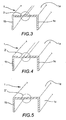
- les figures 3, 4 et 5 représentent un profilé selon l'invention pourvu d'une ligne de pliage obtenue selon trois modes de réalisation,
- les figures 6, 7 et 8 représentent des postes pour des installations de fabrication de profilés selon l'invention, notamment pour réaliser des profilés selon les figures respectivement 3, 4 et 5.
- les figures 9 à 19 représentent en vue d'extrémité divers types de profilés selon l'invention, en position d'utilisation (lettre a) et en position d'empilement (lettre b), c'est-à-dire en forme de W,
- la figure 20 montre une des étapes de fabrication du profilé de la figure 16.
- FIG. 1 is a diagrammatic sectional view of a stack of conventional U-shaped sections,
- FIG. 2 is a diagrammatic sectional view of a stack of profiles according to the invention,
- FIGS. 3, 4 and 5 show a profile according to the invention provided with a folding line obtained according to three embodiments,
- FIGS. 6, 7 and 8 represent stations for profile production installations according to the invention, especially for producing profiles according to FIGS. 3, 4 and 5, respectively.
- FIGS. 9 to 19 show an end view of various types of profiles according to the invention, in the position of use (letter a) and in the stacking position (letter b), that is to say in the form of W,
- FIG. 20 shows one of the steps for manufacturing the profile of FIG. 16.
La figure 1 montre schématiquement un empilement de plusieurs profilés en U classiques. FIG. 1 schematically shows a stack of several sections in U classics.
Les profilés sont associés ici par paire avec une disposition tête-bêche par chevauchement.The profiles are associated here in pairs with a head-to-tail arrangement by overlap.
On peut ainsi aisément constater l'énorme perte de place au stockage et/ou pendant le transport de tels profilés classiques.We can easily see the huge loss of space storage and / or during the transport of such conventional profiles.
Au contraire, la figure 2 montre un empilement de profilés selon l'invention et on peut voir comment de tels profilés permettent un empilement optimisé en assurant un gain très important de place.On the contrary, FIG. 2 shows a stack of profiles according to the invention and we can see how such profiles allow optimized stacking by ensuring a very important gain of place.
Les figures suivantes vont permettre de décrire les particularités et la manière de fabriquer des profilés selon l'invention.The following figures will help to describe the particularities and the way to manufacture profiles according to the invention.
Les figures 3, 4 et 5 montrent trois modes de réalisation selon l'invention.Figures 3, 4 and 5 show three embodiments of the invention.
Les profilés 1 représentés sur lesdites figures 3, 4 et 5 sont en forme de U et
sont constitués d'un fond 1a et de deux ailes latérales 1b et 1c.The
Comme le montrent bien les figures 3 à 5, le fond 1a présente au voisinage
de sa ligne médiane et sur toute sa longueur une ligne de pliage 2, 2', 2" destinée à se
comporter comme une charnière. Toutefois, il est clair que ladite ligne de pliage pourrait
être décalée par rapport à ladite ligne médiane.As is evident from FIGS. 3 to 5, the
Chaque ligne de pliage représentée 2, 2', 2" se présente sur les figures 3, 4
et 5 sous la forme d'une rainure (mot à considérer dans son sens le plus large), la
rainure 2 de la figure 3 étant réalisée par enfoncement de la matière avec son côté
concave sur la face interne du fond 1a du profilé, la rainure 2' étant réalisée par enlèvement
de matière sur la face externe du fond 1a du profilé et la rainure 2" étant réalisée
par incision effectuée sur la face interne du fond 1a du profilé.Each folding line shown 2, 2 ', 2 "is shown in FIGS.
and 5 in the form of a groove (word to be considered in its widest sense), the
Les profilés sont fabriqués en partie de manière connue, par exemple à partir de bandes ou feuilles résistantes, notamment en carton ou sous forme d'un complexe carton-polyoléfines, qui sont contrecollées entre elles.The profiles are partly manufactured in known manner, for example from resistant strips or sheets, in particular of cardboard or in the form of a complex cardboard-polyolefins, which are laminated together.
Généralement, on réalise la ligne de pliage selon l'invention en cours de fabrication lorsque le produit se trouve encore sous forme plane, c'est-à-dire avant la réalisation des ailes par pliage.Generally, the folding line according to the invention is produced during manufacture when the product is still in a flat form, that is to say before embodiment of the wings by folding.
Pour réaliser les lignes de pliage selon les figures 3 à 5, on pourra utiliser des
postes de confection du type de ceux représentés sur les figures 6, 7 et 8, lesquelles
figures montrent l'usinage d'un produit semi-fini 3 en bande pris entre deux moyens
rotatifs respectivement 4, 5; 6, 7; 8, 9.To make the fold lines according to FIGS. 3 to 5, it will be possible to use
clothing stations of the type shown in Figures 6, 7 and 8, which
figures show the machining of a
Les moyens 4, 5 de la figure 6 se présentent sous forme de rouleaux ou cylindres
qui comportent respectivement une saillie circonférentielle 4' pour l'un et une
gorge correspondante 5' pour l'autre de manière à permettre un enfoncement de la
matière afin d'obtenir un profilé selon la figue 3.The
Si les moyens 7 et 9 des figures 7 et 8 sont des rouleaux ou cylindres lisses,
le moyen 6 est un système de fraisage, c'est-à-dire avec enlèvement de matière, et le
moyen 8 un rouleau muni d'un couteau circulaire 8' destiné à faire une incision dans
l'épaisseur de la matière, les postes représentés sur les figures 7 et 8 étant destinés à
réaliser des profilés selon les figures respectivement 4 et 5.If the
Les postes de façonnage représentés sur les figures 6, 7 et 8 sont aménagés entre deux postes classiques de fabrication de profilés en U, tels que les postes de collage et de pressage des bandes, les postes pour mettre en forme (pliage des ailes), les éventuels postes pour envelopper, les postes de tronçonnage, etc.The shaping stations shown in Figures 6, 7 and 8 are arranged between two conventional U-profile production stations, such as sticking and pressing strips, positions to shape (folding wings), any posts to wrap, bucking stations, etc.
Ainsi, invention concerne non seulement les profilés en U pourvus d'une ligne
de pliage 2, 2', 2" ménagée sur le fond 1a du profilé, mais donc aussi le procédé
de fabrication et les moyens pour sa mise en oeuvre.Thus, the invention concerns not only U-shaped profiles provided with a
On comprend aisément que les profilés ainsi obtenus peuvent prendre une
position de stockage et/ou de transport en W, comme représenté notamment sur la
figure 2, simplement en écartant les ailes 1b, 1c l'une de l'autre, tout en pouvant bien
sûr reprendre une position d'utilisation en U en vue, par exemple, de fabriquer un
conteneur d'emballage réalisé à partir de deux profilés en U imbriqués l'un dans l'autre.It is easily understood that the profiles thus obtained can take a
position of storage and / or transport in W, as shown in particular on the
2, simply by spreading the
L'invention propose de très nombreux modes de réalisation comme le montrent notamment les figures 9 à 20, les dessins notés (a) représentant, comme déjà dit, les profilés en position d'utilisation et les dessins notés (b) les profilés en position de stockage et/ou de transport.The invention proposes a very large number of embodiments as shown by in particular FIGS. 9 to 20, the drawings noted (a) representing, as already said, the profiles in position of use and the drawings noted (b) the profiles in position storage and / or transport.
La figure 9 montre un profilé du type de celui de la figure 3 avec une rainure
par enfoncement (laquelle pourrait en outre être réalisée avec une concavité sur la
face externe du fond 1a).FIG. 9 shows a profile of the type of that of FIG. 3 with a groove
by embedding (which could also be done with a concavity on the
outer face of the
La figure 10 montre un profilé du type de celui de la figure 4 avec une rainure réalisée par enlèvement de matière.FIG. 10 shows a profile of the type of that of FIG. 4 with a groove made by removal of material.
La figure 11 montre un mode de réalisation voisin de celui de la figure 10 mais dans lequel la rainure a été réalisée sur la face interne du fond du profilé.FIG. 11 shows an embodiment similar to that of FIG. 10 but in which the groove has been made on the inner face of the bottom of the profile.
Les figures 12 et 13 correspondent respectivement aux figures 10 et 11 mais
dans ces modes de réalisation, la ligne de pliage a été renforcée par une bande de
renfort 10, 10' appliquée sur la face du fond du profilé qui est opposée à la face pourvue
de la rainure formant la ligne de pliage. Figures 12 and 13 correspond respectively to Figures 10 and 11 but
in these embodiments, the fold line has been reinforced by a strip of
Comme le montrent bien les figures 12 et 13, la bande du renfort 10 est appliquée
sur une partie seulement de la largeur du fond, mais elle pourrait être appliquée
sur la totalité de la largeur dudit fond.As clearly shown in FIGS. 12 and 13, the band of the
La figure 14 qui correspond à la figure 13, présente toutefois une enveloppe
11 qui vient renforcer la ligne de pliage, tout en enveloppant une grande partie du profilé
à l'exception de la face du fond pourvue de la rainure, un tel enveloppement pouvant
en outre avoir un effet de rigidification et/ou un but esthétique.Figure 14 which corresponds to Figure 13, however, has an
La figure 15 montre un profilé du type de celui de la figure 5 avec une ligne de pliage ou rainure réalisée par incision.FIG. 15 shows a profile of the type of that of FIG. 5 with a line of folding or grooving made by incision.
Les figures 16 et 17 montrent des profilés pourvus de rainures effectuées aussi par incision mais avec des bandes de renfort respectivement 12, 12' appliquées sur la face du fond pourvue de l'incision (figure 16) ou respectivement la face opposée à celle pourvue de ladite incision (figure 17) d'une manière correspondant dans ce dernier cas à la figure 13.Figures 16 and 17 show profiles provided with grooves made also by incision but with reinforcement strips respectively 12, 12 'applied on the bottom face provided with the incision (Figure 16) or the opposite side respectively to that provided with said incision (Figure 17) in a corresponding manner in this last case in Figure 13.
Dans le mode de réalisation de la figure 16 toutefois, invention propose une particularité intéressante.In the embodiment of FIG. 16, however, the invention proposes a interesting feature.
Pour permettre un pliage aisé (voir la vue b de la figure 16), la bande de renfort
12 présente au niveau de la rainure par incision un repli.To allow easy folding (see view b of FIG. 16), the reinforcing
Pour obtenir le repli susmentionné (c'est-à-dire un double pli en zigzag), on peut utiliser bien sûr tout moyen convenable pour plier et fixer ladite bande après avoir effectué l'incision comme le montre plus en détail la figure 20.To obtain the aforementioned foldback (ie a double zigzag fold), can of course use any suitable means to fold and fix said band after having performed the incision as shown in more detail in Figure 20.
La figure 18 montre un profilé muni d'une rainure comme celles des figures 15 à 17 et correspond à la figure 14 quant à l'enveloppe référencée ici 13.FIG. 18 shows a profile provided with a groove like those in FIGS. 15 to 17 and corresponds to FIG. 14 as to the envelope referenced here 13.
La figure 19 quant à elle, propose un mode de réalisation tout à fait particulier,
dans lequel le profilé en U est obtenu à partir de deux profilés 1', 1" en L réunis
par la tranche de l'une de leurs ailes au moyen d'une bande de jonction 14 rapportée
par exemple par collage sur l'une des faces desdites ailes, comme le montre bien la
figure 19.As for Figure 19, it proposes a very particular embodiment,
in which the U-section is obtained from two L-shaped
Par ailleurs et pour compléter ce dernier mode de réalisation, on peut en outre prévoir dans ce cas un joint de colle et/ou de latex et/ou de silicone, ou autre, ménagé entre les tranches desdites ailes et représenté ici en pointillé en vue d'améliorer l'effet charnière de ce mode de réalisation.Moreover, and to complete this last embodiment, it is also possible to in this case, provide an adhesive joint and / or latex and / or silicone, or other, arranged between the slices of said wings and shown here in dotted lines to improve the hinge effect of this embodiment.
L'invention concerne bien sûr d'autres modes de réalisation possibles que ceux représentés, tels que, par exemple, le mode de réalisation de la figure 9 avec une bande de renfort, le mode de réalisation de la figure 19 avec une bande de jonction plus enveloppante, etc.The invention of course relates to other possible embodiments that those shown, such as, for example, the embodiment of Figure 9 with a reinforcing strip, the embodiment of FIG. 19 with a joining strip more enveloping, etc.
Claims (13)
- U-section (1) including a base (1a) and two lateral wings (1b, 1c), characterised by the fact that it is provided in its base (1a) with a longitudinal fold line (2, 2', 2") so that the said base (1a) can be folded inwardly simultaneously as the wings (1b, 1c) are opened out, in such a way that the section can as required adopt a substantially W-shaped form, thus facilitating its stacking in particular for its storage and/or transport.
- Section (1) as described in claim 1, characterised by the fact that the longitudinal fold line (2, 2', 2") is situated substantially in the vicinity of the median line of the base (1a) of the section.
- Process for manufacture of a U-section (1) as described in one of claims 1 and 2, characterised by the fact that it consists, during the manufacture of the section, of providing a step of formation of a longitudinal fold line (2, 2', 2") in the base (1a) of the said section.
- Process as described in claim 3, characterised by the fact that the fold line (2, 2', 2") is created in a semi-finished product, before creation of the wings (1b, 1c) of the section (1) by folding.
- Process as described in one of claims 3 and 4 for manufacture of U-sections from strips of laminated material, in particular made of cardboard or a cardboard-polyolefin complex, characterised by the fact that it consists of creating a fold line (2, 2', 2") by a grooving operation.
- Process as described in claim 5, characterised by the fact that the grooving operation is effected by crushing (2) without removal of material.
- Process as described in claim 5, characterised by the fact that the grooving operation is effected by milling (2') with removal of material.
- Process as described in claim 5, characterised by the fact that the grooving operation is effected by incision (2") on the inside face of the base (1a).
- Process as described in one of claims 3 to 8, characterised by the fact that the fold line (2, 2', 2") is reinforced on at least one of the faces of the base of the section by an attached reinforcement strip (10, 10', 12, 12').
- Process as described in claims 8 and 9 taken together, characterised by the fact that it consists of arranging the reinforcement strip (12) over the incision, forming a fold in this position to allow folding of the section.
- Process as described in one of claims 9 and 10, characterised by the fact that it consists of enveloping with the reinforcement strip (11, 13) a large part of the section with the exception of at least a part of one of the faces of the base (1a) of the said section in the location of the fold line of the latter.
- Process as described in claim 3, characterised by the fact that it consists of joining two butted L-sections (1, 1') to each other by one of their wings by means of a joining strip (14) fixed onto the said wings.
- Apparatus for implementing the process as described in one of claims 3 to 11, characterised by the fact that it includes, in addition to the known stations for making a U-section (1), a grooving station (4, 5; 6, 7; 8, 9) arranged to form a longitudinal groove (2, 2', 2") in the part of the section which is to form the base (1a) of the said U-section.
Applications Claiming Priority (2)
| Application Number | Priority Date | Filing Date | Title |
|---|---|---|---|
| FR9816494A FR2787861B1 (en) | 1998-12-28 | 1998-12-28 | FOLDABLE U-PROFILE, MANUFACTURING METHOD THEREOF, AND INSTALLATION FOR IMPLEMENTING THE METHOD |
| FR9816494 | 1998-12-28 |
Publications (2)
| Publication Number | Publication Date |
|---|---|
| EP1016596A1 EP1016596A1 (en) | 2000-07-05 |
| EP1016596B1 true EP1016596B1 (en) | 2005-09-07 |
Family
ID=9534551
Family Applications (1)
| Application Number | Title | Priority Date | Filing Date |
|---|---|---|---|
| EP99402868A Expired - Lifetime EP1016596B1 (en) | 1998-12-28 | 1999-11-19 | U-shaped profile |
Country Status (11)
| Country | Link |
|---|---|
| US (1) | US6457636B1 (en) |
| EP (1) | EP1016596B1 (en) |
| AT (1) | ATE303954T1 (en) |
| CA (1) | CA2292683C (en) |
| DE (1) | DE69927120T2 (en) |
| DK (1) | DK1016596T3 (en) |
| ES (1) | ES2248971T3 (en) |
| FR (1) | FR2787861B1 (en) |
| MA (1) | MA25041A1 (en) |
| NO (1) | NO326055B1 (en) |
| PL (1) | PL196782B1 (en) |
Families Citing this family (17)
| Publication number | Priority date | Publication date | Assignee | Title |
|---|---|---|---|---|
| DE10327962B4 (en) * | 2003-05-05 | 2005-10-20 | Frank Smolka | Transport container with compartment division |
| NZ527968A (en) * | 2003-09-01 | 2006-07-28 | H2Safe Llc | Storage vessel |
| US20050167310A1 (en) * | 2004-02-03 | 2005-08-04 | Harel Kenneth N. | Drywall trim reinforced package and method of packaging such drywall trim |
| US7909189B2 (en) * | 2005-02-18 | 2011-03-22 | Kellogg Company | Bulk transport system for dense products |
| US20070215495A1 (en) * | 2006-03-17 | 2007-09-20 | Illinois Tool Works, Inc. | Rigid u-shaped packaging container with integral handle |
| US8485422B2 (en) * | 2009-01-29 | 2013-07-16 | Illinois Tool Works Inc. | Nestable rigid U-crates |
| US8770465B2 (en) * | 2009-02-13 | 2014-07-08 | Premark Packaging Llc | Corner lock board |
| US8511494B2 (en) * | 2009-03-31 | 2013-08-20 | Illinois Tool Works Inc. | Four-sided container |
| US8474687B2 (en) * | 2010-01-25 | 2013-07-02 | Illinois Tool Works Inc. | Nestable rigid U-crates |
| WO2012146645A1 (en) | 2011-04-27 | 2012-11-01 | Roche Diagnostics Gmbh | Diagnosis of kidney injury after surgery |
| US9169063B2 (en) * | 2012-05-29 | 2015-10-27 | Sierra Packaging Solutions | Corner boards, container assemblies including the same, and methods of making and using the same |
| US9511920B2 (en) | 2013-07-09 | 2016-12-06 | T & M Design, Llc | Edge protector |
| US10886517B2 (en) * | 2014-02-11 | 2021-01-05 | Ford Global Technologies, Llc | Battery cell spacer |
| CN104354954A (en) * | 2014-10-09 | 2015-02-18 | 厦门东群纸品有限公司 | Packing box |
| BR112017008250B1 (en) | 2014-10-24 | 2022-04-12 | H2Safe, Llc | Fail-Safe Container Insert and Fail-Safe Container |
| CA2945654C (en) * | 2015-10-20 | 2024-01-09 | Todd Fluery | Angle edge protector having a cover |
| CN110558801A (en) * | 2018-06-05 | 2019-12-13 | 歌乐电磁(深圳)有限公司 | tableware handle and tableware thereof |
Family Cites Families (9)
| Publication number | Priority date | Publication date | Assignee | Title |
|---|---|---|---|---|
| US769915A (en) * | 1903-12-07 | 1904-09-13 | Franz E Habicht | Receptacle for shipping and exposing fly-paper. |
| US2198634A (en) * | 1934-05-25 | 1940-04-30 | Richter Herman William | Molding apparatus |
| US2961123A (en) * | 1958-06-27 | 1960-11-22 | Diamond National Corp | Molded pulp bottle carrier |
| US3275188A (en) * | 1965-01-18 | 1966-09-27 | Banner Metals Inc | Receptacle |
| US3339722A (en) * | 1965-10-08 | 1967-09-05 | Vanant Company Inc | Package and cushioning strip for fragile articles |
| US3669338A (en) * | 1970-07-15 | 1972-06-13 | Richard Cornell & Associates | Packing container or the like |
| US4976374A (en) * | 1988-04-11 | 1990-12-11 | Cornerboard, Inc. | Packing container |
| JP3073211B2 (en) * | 1988-04-11 | 2000-08-07 | イリノイ ツール ワークス,インコーポレイテッド | Packing container |
| US5947290A (en) * | 1998-07-20 | 1999-09-07 | Illinois Tool Works Inc. | Scored U-shaped packaging members |
-
1998
- 1998-12-28 FR FR9816494A patent/FR2787861B1/en not_active Expired - Fee Related
-
1999
- 1999-11-19 EP EP99402868A patent/EP1016596B1/en not_active Expired - Lifetime
- 1999-11-19 DK DK99402868T patent/DK1016596T3/en active
- 1999-11-19 DE DE69927120T patent/DE69927120T2/en not_active Expired - Fee Related
- 1999-11-19 AT AT99402868T patent/ATE303954T1/en not_active IP Right Cessation
- 1999-11-19 ES ES99402868T patent/ES2248971T3/en not_active Expired - Lifetime
- 1999-12-17 CA CA002292683A patent/CA2292683C/en not_active Expired - Lifetime
- 1999-12-27 NO NO19996486A patent/NO326055B1/en not_active IP Right Cessation
- 1999-12-27 PL PL337479A patent/PL196782B1/en not_active IP Right Cessation
- 1999-12-27 US US09/472,204 patent/US6457636B1/en not_active Expired - Lifetime
- 1999-12-28 MA MA25874A patent/MA25041A1/en unknown
Also Published As
| Publication number | Publication date |
|---|---|
| NO326055B1 (en) | 2008-09-08 |
| DE69927120D1 (en) | 2005-10-13 |
| DK1016596T3 (en) | 2005-10-31 |
| CA2292683A1 (en) | 2000-06-28 |
| DE69927120T2 (en) | 2006-01-19 |
| MA25041A1 (en) | 2000-07-01 |
| EP1016596A1 (en) | 2000-07-05 |
| FR2787861B1 (en) | 2001-03-23 |
| NO996486L (en) | 2000-06-29 |
| NO996486D0 (en) | 1999-12-27 |
| CA2292683C (en) | 2005-03-29 |
| ATE303954T1 (en) | 2005-09-15 |
| ES2248971T3 (en) | 2006-03-16 |
| FR2787861A1 (en) | 2000-06-30 |
| PL196782B1 (en) | 2008-01-31 |
| PL337479A1 (en) | 2000-07-03 |
| US6457636B1 (en) | 2002-10-01 |
Similar Documents
| Publication | Publication Date | Title |
|---|---|---|
| EP1016596B1 (en) | U-shaped profile | |
| EP2035288B1 (en) | Plastic bag with gussets for food products and its method of manufacture | |
| EP0052021B1 (en) | Paperboard carton lined with a plastics film and provided with a one-piece circumferential frame, and method of making the same | |
| EP1226929B1 (en) | Process and machine for production of zipper gusset bags | |
| EP1410999B1 (en) | Reclosable flexible package | |
| EP2872409B1 (en) | Package of the two-material box type for packaging a product, and method of manufacture | |
| EP2709826B1 (en) | Composite panel and process for producing same | |
| WO2013057392A1 (en) | Method of producing a packaging box and a box obtained according to this method | |
| EP3708511A1 (en) | Packing bag with facilitated recycling, and method for manufacturing such a bag | |
| EP1348635B1 (en) | Blank for package out of semi-rigid material comprising on one surface a heat shrinkable film | |
| FR3038886B1 (en) | PACKING BOX FOLDING MACHINE AND ADAPTIVE PACKING BOX | |
| FR2811741A1 (en) | METHOD FOR MANUFACTURING A STRUCTURAL ELEMENT HAVING A METALLIC WALL OF TUBULAR GENERAL FORM AND STRUCTURAL ELEMENT | |
| EP1836110B1 (en) | Plastic packaging and production and packaging method | |
| FR2588505A1 (en) | METHOD FOR THE TWO-WALL OR TWO-SIDED ASSEMBLY OF A PACKAGE MADE FROM A SINGLE FLAN OR MULTIPLE FLANS OF CARDBOARD AND THE PACKAGE PRODUCED THEREBY | |
| FR2825981A1 (en) | Package comprises cylindrical, transparent body which fits between lid and base, opaque or translucent sleeve fitted over body having aperture in it, forming window for package | |
| EP3144236B1 (en) | Flat precursor for a package, method and package | |
| FR2687379A1 (en) | Shrink film package | |
| FR2828170A1 (en) | Blank for forming carton comprises central section, forming base, side sections and end flaps with tabs which fit inside carton and fasten it together, separate sheet with peripheral flaps forming lid | |
| FR2861365A1 (en) | Flexible vented thermal insulation material packaging method for e.g. garage door, comprises compressing panel, obtained by folding material in accordion, using platen, and associating package to panel to maintain panel in compressed state | |
| EP2444328B1 (en) | Plastic housing with optimised detachable protection strip | |
| EP1299292B1 (en) | Packaging particularly designed for fragile products and method for making same | |
| EP1561194B1 (en) | Printed document folded in several flaps | |
| EP3708510A1 (en) | Packing bag with facilitated recycling, and method for continuous production of a plurality of bags of this type | |
| EP1666374A1 (en) | Blank and cushioning corner for a packaging and methods of manufacturing of a plate for making the blank and of making the cushioning corner from the plate | |
| FR2865716A1 (en) | CONTAINER IN FOLDABLE SHEET MATERIAL. |
Legal Events
| Date | Code | Title | Description |
|---|---|---|---|
| PUAI | Public reference made under article 153(3) epc to a published international application that has entered the european phase |
Free format text: ORIGINAL CODE: 0009012 |
|
| 17P | Request for examination filed |
Effective date: 19991130 |
|
| AK | Designated contracting states |
Kind code of ref document: A1 Designated state(s): AT BE CH CY DE DK ES FI FR GB GR IE IT LI LU MC NL PT SE |
|
| AX | Request for extension of the european patent |
Free format text: AL;LT;LV;MK;RO;SI |
|
| AKX | Designation fees paid |
Free format text: AT BE CH CY DE DK ES FI FR GB GR IE IT LI LU MC NL PT SE |
|
| GRAP | Despatch of communication of intention to grant a patent |
Free format text: ORIGINAL CODE: EPIDOSNIGR1 |
|
| GRAS | Grant fee paid |
Free format text: ORIGINAL CODE: EPIDOSNIGR3 |
|
| GRAA | (expected) grant |
Free format text: ORIGINAL CODE: 0009210 |
|
| AK | Designated contracting states |
Kind code of ref document: B1 Designated state(s): AT BE CH CY DE DK ES FI FR GB GR IE IT LI LU MC NL PT SE |
|
| PG25 | Lapsed in a contracting state [announced via postgrant information from national office to epo] |
Ref country code: IE Free format text: LAPSE BECAUSE OF FAILURE TO SUBMIT A TRANSLATION OF THE DESCRIPTION OR TO PAY THE FEE WITHIN THE PRESCRIBED TIME-LIMIT Effective date: 20050907 |
|
| REG | Reference to a national code |
Ref country code: GB Ref legal event code: FG4D Free format text: NOT ENGLISH |
|
| REG | Reference to a national code |
Ref country code: CH Ref legal event code: NV Representative=s name: E. BLUM & CO. PATENTANWAELTE Ref country code: CH Ref legal event code: EP |
|
| GBT | Gb: translation of ep patent filed (gb section 77(6)(a)/1977) |
Effective date: 20050907 |
|
| REG | Reference to a national code |
Ref country code: IE Ref legal event code: FG4D Free format text: LANGUAGE OF EP DOCUMENT: FRENCH |
|
| REF | Corresponds to: |
Ref document number: 69927120 Country of ref document: DE Date of ref document: 20051013 Kind code of ref document: P |
|
| REG | Reference to a national code |
Ref country code: DK Ref legal event code: T3 |
|
| PG25 | Lapsed in a contracting state [announced via postgrant information from national office to epo] |
Ref country code: CY Free format text: LAPSE BECAUSE OF FAILURE TO SUBMIT A TRANSLATION OF THE DESCRIPTION OR TO PAY THE FEE WITHIN THE PRESCRIBED TIME-LIMIT Effective date: 20051119 |
|
| PG25 | Lapsed in a contracting state [announced via postgrant information from national office to epo] |
Ref country code: MC Free format text: LAPSE BECAUSE OF NON-PAYMENT OF DUE FEES Effective date: 20051130 Ref country code: LU Free format text: LAPSE BECAUSE OF NON-PAYMENT OF DUE FEES Effective date: 20051130 |
|
| REG | Reference to a national code |
Ref country code: SE Ref legal event code: TRGR |
|
| PG25 | Lapsed in a contracting state [announced via postgrant information from national office to epo] |
Ref country code: GR Free format text: LAPSE BECAUSE OF FAILURE TO SUBMIT A TRANSLATION OF THE DESCRIPTION OR TO PAY THE FEE WITHIN THE PRESCRIBED TIME-LIMIT Effective date: 20051207 |
|
| REG | Reference to a national code |
Ref country code: ES Ref legal event code: FG2A Ref document number: 2248971 Country of ref document: ES Kind code of ref document: T3 |
|
| REG | Reference to a national code |
Ref country code: IE Ref legal event code: FD4D |
|
| PLBE | No opposition filed within time limit |
Free format text: ORIGINAL CODE: 0009261 |
|
| STAA | Information on the status of an ep patent application or granted ep patent |
Free format text: STATUS: NO OPPOSITION FILED WITHIN TIME LIMIT |
|
| 26N | No opposition filed |
Effective date: 20060608 |
|
| REG | Reference to a national code |
Ref country code: CH Ref legal event code: PFA Owner name: ITW LITEC FRANCE, SOCIETE PAR ACTIONS SIMPLIFIEE Free format text: ITW LITEC FRANCE, SOCIETE PAR ACTIONS SIMPLIFIEE#ZONE INDUSTRIELLE DES JONCS#71700 TOURNUS (FR) -TRANSFER TO- ITW LITEC FRANCE, SOCIETE PAR ACTIONS SIMPLIFIEE#ZONE INDUSTRIELLE DES JONCS#71700 TOURNUS (FR) |
|
| PGFP | Annual fee paid to national office [announced via postgrant information from national office to epo] |
Ref country code: NL Payment date: 20081223 Year of fee payment: 10 Ref country code: DK Payment date: 20081230 Year of fee payment: 10 Ref country code: CH Payment date: 20081229 Year of fee payment: 10 |
|
| PGFP | Annual fee paid to national office [announced via postgrant information from national office to epo] |
Ref country code: PT Payment date: 20081031 Year of fee payment: 10 Ref country code: FI Payment date: 20081230 Year of fee payment: 10 Ref country code: ES Payment date: 20081226 Year of fee payment: 10 Ref country code: AT Payment date: 20081103 Year of fee payment: 10 |
|
| PGFP | Annual fee paid to national office [announced via postgrant information from national office to epo] |
Ref country code: SE Payment date: 20081128 Year of fee payment: 10 Ref country code: IT Payment date: 20081126 Year of fee payment: 10 |
|
| PGFP | Annual fee paid to national office [announced via postgrant information from national office to epo] |
Ref country code: FR Payment date: 20081117 Year of fee payment: 10 |
|
| PGFP | Annual fee paid to national office [announced via postgrant information from national office to epo] |
Ref country code: DE Payment date: 20081223 Year of fee payment: 10 |
|
| PGFP | Annual fee paid to national office [announced via postgrant information from national office to epo] |
Ref country code: GB Payment date: 20081229 Year of fee payment: 10 |
|
| PGFP | Annual fee paid to national office [announced via postgrant information from national office to epo] |
Ref country code: BE Payment date: 20090202 Year of fee payment: 10 |
|
| REG | Reference to a national code |
Ref country code: PT Ref legal event code: MM4A Free format text: LAPSE DUE TO NON-PAYMENT OF FEES Effective date: 20100519 |
|
| BERE | Be: lapsed |
Owner name: *ITW LITEC FRANCE Effective date: 20091130 |
|
| REG | Reference to a national code |
Ref country code: NL Ref legal event code: V1 Effective date: 20100601 |
|
| EUG | Se: european patent has lapsed | ||
| REG | Reference to a national code |
Ref country code: CH Ref legal event code: PL |
|
| REG | Reference to a national code |
Ref country code: DK Ref legal event code: EBP |
|
| GBPC | Gb: european patent ceased through non-payment of renewal fee |
Effective date: 20091119 |
|
| PG25 | Lapsed in a contracting state [announced via postgrant information from national office to epo] |
Ref country code: PT Free format text: LAPSE BECAUSE OF NON-PAYMENT OF DUE FEES Effective date: 20100519 |
|
| REG | Reference to a national code |
Ref country code: FR Ref legal event code: ST Effective date: 20100730 |
|
| PG25 | Lapsed in a contracting state [announced via postgrant information from national office to epo] |
Ref country code: FI Free format text: LAPSE BECAUSE OF NON-PAYMENT OF DUE FEES Effective date: 20091119 Ref country code: AT Free format text: LAPSE BECAUSE OF NON-PAYMENT OF DUE FEES Effective date: 20091119 |
|
| PG25 | Lapsed in a contracting state [announced via postgrant information from national office to epo] |
Ref country code: NL Free format text: LAPSE BECAUSE OF NON-PAYMENT OF DUE FEES Effective date: 20100601 Ref country code: LI Free format text: LAPSE BECAUSE OF NON-PAYMENT OF DUE FEES Effective date: 20091130 Ref country code: FR Free format text: LAPSE BECAUSE OF NON-PAYMENT OF DUE FEES Effective date: 20091130 Ref country code: CH Free format text: LAPSE BECAUSE OF NON-PAYMENT OF DUE FEES Effective date: 20091130 Ref country code: BE Free format text: LAPSE BECAUSE OF NON-PAYMENT OF DUE FEES Effective date: 20091130 |
|
| PG25 | Lapsed in a contracting state [announced via postgrant information from national office to epo] |
Ref country code: DE Free format text: LAPSE BECAUSE OF NON-PAYMENT OF DUE FEES Effective date: 20100601 |
|
| PG25 | Lapsed in a contracting state [announced via postgrant information from national office to epo] |
Ref country code: GB Free format text: LAPSE BECAUSE OF NON-PAYMENT OF DUE FEES Effective date: 20091119 |
|
| PG25 | Lapsed in a contracting state [announced via postgrant information from national office to epo] |
Ref country code: DK Free format text: LAPSE BECAUSE OF NON-PAYMENT OF DUE FEES Effective date: 20091130 |
|
| REG | Reference to a national code |
Ref country code: ES Ref legal event code: FD2A Effective date: 20110310 |
|
| PG25 | Lapsed in a contracting state [announced via postgrant information from national office to epo] |
Ref country code: IT Free format text: LAPSE BECAUSE OF NON-PAYMENT OF DUE FEES Effective date: 20091119 |
|
| PG25 | Lapsed in a contracting state [announced via postgrant information from national office to epo] |
Ref country code: SE Free format text: LAPSE BECAUSE OF NON-PAYMENT OF DUE FEES Effective date: 20091120 |
|
| PG25 | Lapsed in a contracting state [announced via postgrant information from national office to epo] |
Ref country code: ES Free format text: LAPSE BECAUSE OF NON-PAYMENT OF DUE FEES Effective date: 20110309 |
|
| PG25 | Lapsed in a contracting state [announced via postgrant information from national office to epo] |
Ref country code: ES Free format text: LAPSE BECAUSE OF NON-PAYMENT OF DUE FEES Effective date: 20091120 |