EP1015903B1 - Simultaneous acquisition of spatial basis functions: ultra-fast imaging with radiofrequency coil arrays - Google Patents
Simultaneous acquisition of spatial basis functions: ultra-fast imaging with radiofrequency coil arrays Download PDFInfo
- Publication number
- EP1015903B1 EP1015903B1 EP97948164A EP97948164A EP1015903B1 EP 1015903 B1 EP1015903 B1 EP 1015903B1 EP 97948164 A EP97948164 A EP 97948164A EP 97948164 A EP97948164 A EP 97948164A EP 1015903 B1 EP1015903 B1 EP 1015903B1
- Authority
- EP
- European Patent Office
- Prior art keywords
- coil
- coils
- imaging
- image
- signals
- Prior art date
- Legal status (The legal status is an assumption and is not a legal conclusion. Google has not performed a legal analysis and makes no representation as to the accuracy of the status listed.)
- Expired - Lifetime
Links
- 238000003384 imaging method Methods 0.000 title claims description 65
- 230000006870 function Effects 0.000 title claims description 24
- 238000003491 array Methods 0.000 title description 19
- 230000035945 sensitivity Effects 0.000 claims description 107
- 238000000034 method Methods 0.000 claims description 62
- 239000011159 matrix material Substances 0.000 claims description 39
- 238000002595 magnetic resonance imaging Methods 0.000 claims description 21
- 239000002131 composite material Substances 0.000 claims description 19
- 238000005259 measurement Methods 0.000 claims description 10
- 230000004044 response Effects 0.000 claims description 9
- 230000008878 coupling Effects 0.000 claims description 7
- 238000010168 coupling process Methods 0.000 claims description 7
- 238000005859 coupling reaction Methods 0.000 claims description 7
- 230000001939 inductive effect Effects 0.000 claims description 7
- 230000009466 transformation Effects 0.000 claims description 7
- 230000003750 conditioning effect Effects 0.000 claims description 6
- 238000013479 data entry Methods 0.000 claims 2
- 238000012545 processing Methods 0.000 description 13
- 238000013459 approach Methods 0.000 description 12
- 230000000747 cardiac effect Effects 0.000 description 11
- 230000008569 process Effects 0.000 description 11
- 238000005481 NMR spectroscopy Methods 0.000 description 9
- 230000001965 increasing effect Effects 0.000 description 9
- 230000006872 improvement Effects 0.000 description 8
- 238000004422 calculation algorithm Methods 0.000 description 7
- 238000012805 post-processing Methods 0.000 description 7
- 230000008901 benefit Effects 0.000 description 6
- 238000001727 in vivo Methods 0.000 description 6
- 238000010276 construction Methods 0.000 description 5
- 238000001208 nuclear magnetic resonance pulse sequence Methods 0.000 description 5
- 238000002360 preparation method Methods 0.000 description 5
- 238000004088 simulation Methods 0.000 description 5
- 238000013480 data collection Methods 0.000 description 4
- 238000013461 design Methods 0.000 description 4
- 238000001514 detection method Methods 0.000 description 4
- 230000005284 excitation Effects 0.000 description 4
- 238000000264 spin echo pulse sequence Methods 0.000 description 4
- 210000004351 coronary vessel Anatomy 0.000 description 3
- 230000000241 respiratory effect Effects 0.000 description 3
- 230000003044 adaptive effect Effects 0.000 description 2
- 238000013528 artificial neural network Methods 0.000 description 2
- 230000015572 biosynthetic process Effects 0.000 description 2
- 230000015556 catabolic process Effects 0.000 description 2
- 238000012937 correction Methods 0.000 description 2
- 238000006731 degradation reaction Methods 0.000 description 2
- 238000002592 echocardiography Methods 0.000 description 2
- 230000000694 effects Effects 0.000 description 2
- 238000005516 engineering process Methods 0.000 description 2
- 238000011503 in vivo imaging Methods 0.000 description 2
- 238000005457 optimization Methods 0.000 description 2
- 230000002685 pulmonary effect Effects 0.000 description 2
- 230000009467 reduction Effects 0.000 description 2
- 238000000926 separation method Methods 0.000 description 2
- 230000003068 static effect Effects 0.000 description 2
- 210000005166 vasculature Anatomy 0.000 description 2
- XLYOFNOQVPJJNP-UHFFFAOYSA-N water Substances O XLYOFNOQVPJJNP-UHFFFAOYSA-N 0.000 description 2
- 210000001015 abdomen Anatomy 0.000 description 1
- 230000000712 assembly Effects 0.000 description 1
- 238000000429 assembly Methods 0.000 description 1
- 238000010009 beating Methods 0.000 description 1
- 210000004204 blood vessel Anatomy 0.000 description 1
- 210000004556 brain Anatomy 0.000 description 1
- 238000004364 calculation method Methods 0.000 description 1
- 230000008859 change Effects 0.000 description 1
- 238000006243 chemical reaction Methods 0.000 description 1
- 230000001427 coherent effect Effects 0.000 description 1
- 230000000295 complement effect Effects 0.000 description 1
- 235000009508 confectionery Nutrition 0.000 description 1
- 230000001934 delay Effects 0.000 description 1
- 238000000331 delays alternating with nutation for tailored excitation Methods 0.000 description 1
- 230000001419 dependent effect Effects 0.000 description 1
- 230000002708 enhancing effect Effects 0.000 description 1
- 238000011156 evaluation Methods 0.000 description 1
- 238000002474 experimental method Methods 0.000 description 1
- 238000003863 fast low-angle shot imaging Methods 0.000 description 1
- 238000001914 filtration Methods 0.000 description 1
- 238000002124 flame ionisation detection Methods 0.000 description 1
- 230000010354 integration Effects 0.000 description 1
- 102000003898 interleukin-24 Human genes 0.000 description 1
- 108090000237 interleukin-24 Proteins 0.000 description 1
- 238000013507 mapping Methods 0.000 description 1
- 239000000463 material Substances 0.000 description 1
- 230000007246 mechanism Effects 0.000 description 1
- 238000002156 mixing Methods 0.000 description 1
- 238000012986 modification Methods 0.000 description 1
- 230000004048 modification Effects 0.000 description 1
- 238000010606 normalization Methods 0.000 description 1
- 210000004789 organ system Anatomy 0.000 description 1
- 230000010355 oscillation Effects 0.000 description 1
- 230000001991 pathophysiological effect Effects 0.000 description 1
- 230000003094 perturbing effect Effects 0.000 description 1
- 230000010363 phase shift Effects 0.000 description 1
- 238000005215 recombination Methods 0.000 description 1
- 230000006798 recombination Effects 0.000 description 1
- 230000011218 segmentation Effects 0.000 description 1
- 239000013589 supplement Substances 0.000 description 1
- 230000009897 systematic effect Effects 0.000 description 1
- 230000002123 temporal effect Effects 0.000 description 1
- 230000001131 transforming effect Effects 0.000 description 1
- 230000000007 visual effect Effects 0.000 description 1
- 238000011179 visual inspection Methods 0.000 description 1
- 239000002699 waste material Substances 0.000 description 1
Images


Classifications
-
- G—PHYSICS
- G01—MEASURING; TESTING
- G01R—MEASURING ELECTRIC VARIABLES; MEASURING MAGNETIC VARIABLES
- G01R33/00—Arrangements or instruments for measuring magnetic variables
- G01R33/20—Arrangements or instruments for measuring magnetic variables involving magnetic resonance
- G01R33/28—Details of apparatus provided for in groups G01R33/44 - G01R33/64
- G01R33/38—Systems for generation, homogenisation or stabilisation of the main or gradient magnetic field
- G01R33/381—Systems for generation, homogenisation or stabilisation of the main or gradient magnetic field using electromagnets
- G01R33/3815—Systems for generation, homogenisation or stabilisation of the main or gradient magnetic field using electromagnets with superconducting coils, e.g. power supply therefor
-
- G—PHYSICS
- G01—MEASURING; TESTING
- G01R—MEASURING ELECTRIC VARIABLES; MEASURING MAGNETIC VARIABLES
- G01R33/00—Arrangements or instruments for measuring magnetic variables
- G01R33/20—Arrangements or instruments for measuring magnetic variables involving magnetic resonance
- G01R33/44—Arrangements or instruments for measuring magnetic variables involving magnetic resonance using nuclear magnetic resonance [NMR]
- G01R33/48—NMR imaging systems
- G01R33/54—Signal processing systems, e.g. using pulse sequences ; Generation or control of pulse sequences; Operator console
- G01R33/56—Image enhancement or correction, e.g. subtraction or averaging techniques, e.g. improvement of signal-to-noise ratio and resolution
- G01R33/561—Image enhancement or correction, e.g. subtraction or averaging techniques, e.g. improvement of signal-to-noise ratio and resolution by reduction of the scanning time, i.e. fast acquiring systems, e.g. using echo-planar pulse sequences
- G01R33/5611—Parallel magnetic resonance imaging, e.g. sensitivity encoding [SENSE], simultaneous acquisition of spatial harmonics [SMASH], unaliasing by Fourier encoding of the overlaps using the temporal dimension [UNFOLD], k-t-broad-use linear acquisition speed-up technique [k-t-BLAST], k-t-SENSE
-
- G—PHYSICS
- G01—MEASURING; TESTING
- G01R—MEASURING ELECTRIC VARIABLES; MEASURING MAGNETIC VARIABLES
- G01R33/00—Arrangements or instruments for measuring magnetic variables
- G01R33/20—Arrangements or instruments for measuring magnetic variables involving magnetic resonance
- G01R33/44—Arrangements or instruments for measuring magnetic variables involving magnetic resonance using nuclear magnetic resonance [NMR]
- G01R33/48—NMR imaging systems
- G01R33/4818—MR characterised by data acquisition along a specific k-space trajectory or by the temporal order of k-space coverage, e.g. centric or segmented coverage of k-space
- G01R33/4824—MR characterised by data acquisition along a specific k-space trajectory or by the temporal order of k-space coverage, e.g. centric or segmented coverage of k-space using a non-Cartesian trajectory
-
- G—PHYSICS
- G01—MEASURING; TESTING
- G01R—MEASURING ELECTRIC VARIABLES; MEASURING MAGNETIC VARIABLES
- G01R33/00—Arrangements or instruments for measuring magnetic variables
- G01R33/20—Arrangements or instruments for measuring magnetic variables involving magnetic resonance
- G01R33/44—Arrangements or instruments for measuring magnetic variables involving magnetic resonance using nuclear magnetic resonance [NMR]
- G01R33/48—NMR imaging systems
- G01R33/54—Signal processing systems, e.g. using pulse sequences ; Generation or control of pulse sequences; Operator console
- G01R33/56—Image enhancement or correction, e.g. subtraction or averaging techniques, e.g. improvement of signal-to-noise ratio and resolution
- G01R33/5608—Data processing and visualization specially adapted for MR, e.g. for feature analysis and pattern recognition on the basis of measured MR data, segmentation of measured MR data, edge contour detection on the basis of measured MR data, for enhancing measured MR data in terms of signal-to-noise ratio by means of noise filtering or apodization, for enhancing measured MR data in terms of resolution by means for deblurring, windowing, zero filling, or generation of gray-scaled images, colour-coded images or images displaying vectors instead of pixels
-
- G—PHYSICS
- G01—MEASURING; TESTING
- G01R—MEASURING ELECTRIC VARIABLES; MEASURING MAGNETIC VARIABLES
- G01R33/00—Arrangements or instruments for measuring magnetic variables
- G01R33/20—Arrangements or instruments for measuring magnetic variables involving magnetic resonance
- G01R33/44—Arrangements or instruments for measuring magnetic variables involving magnetic resonance using nuclear magnetic resonance [NMR]
- G01R33/48—NMR imaging systems
- G01R33/54—Signal processing systems, e.g. using pulse sequences ; Generation or control of pulse sequences; Operator console
- G01R33/56—Image enhancement or correction, e.g. subtraction or averaging techniques, e.g. improvement of signal-to-noise ratio and resolution
- G01R33/561—Image enhancement or correction, e.g. subtraction or averaging techniques, e.g. improvement of signal-to-noise ratio and resolution by reduction of the scanning time, i.e. fast acquiring systems, e.g. using echo-planar pulse sequences
Definitions
- This invention is generally related to magnetic resonance imaging (MRI) using nuclear magnetic resonance (NMR) phenomena. It is particularly directed to a method and corresponding apparatus for more efficiently capturing and providing MRI data suitable for use in multi-dimensional imaging processes.
- MRI magnetic resonance imaging
- NMR nuclear magnetic resonance
- MRI is by now a widely accepted, medically important and commercially viable technique for obtaining digitized video images representative of internal body tissue and structures.
- MRI devices establish a constant homogeneous magnetic field, apply a specific additional bias field gradient in a known plane or region under consideration to orient nuclear spins, and apply a radiofrequency pulse or a sequence of pulses to perturb the nuclei.
- These nuclei in the known bias field gradient emit an RF signal in a specific band determined by the magnetic field distribution, and these RF emissions are detected by receiving coils and stored as a line of information in a data matrix known as the k-space matrix.
- the full matrix is built up by successive cycles of conditioning the spins, perturbing them, and collecting RF emissions.
- An image is then generated from this matrix by Fourier transformation, which converts the frequency information present in the RF oscillations to spatial information representing the distribution of nuclear spins in tissue or other imaged material.
- Magnetic resonance imaging has proven to be a valuable clinical diagnostic tool in a wide range of organ systems and pathophysiologic processes. Both anatomic and functional information can be gleaned from the MR data, and new applications continue to develop with each improvement in basic imaging technique and technology. As technologic advances have improved achievable spatial resolution, for example, increasingly finer anatomic details have been able to be imaged and evaluated using MR. At the same time, fast imaging sequences have reduced imaging times to such an extent that many moving structures can now be visualized without significant motion artifacts.
- MR magnetic resonance
- the speed with which magnetic resonance (MR) images may be acquired has already increased dramatically over the past decade.
- the improvements in speed may be traced to a combination of advances in the technologies of magnet construction and actuation, and innovations in imaging strategy.
- Strong, fast-switching magnetic field gradients and fast electronics have allowed the intervals between data collections to be reduced significantly.
- fast gradient-echo and spin-echo sequences have reduced image acquisition time by allowing greater portions of k -space to be sampled after each spin excitation.
- Echo planar imaging (EPI), fast low-angle shot (FLASH), turbo spin echo (TSE), and spiral imaging techniques all allow very short intervals between acquisition of successive data points.
- the DUFIS, OUFIS, RUFIS, and BURST family of sequences further reduce image acquisition time by eliminating time delays incurred during gradient switching and echo formation. Details of the above-mentioned eight techniques may be found in the following papers: P. Mansfield, Multiplanar image formation using NMR spin echoes . J. Phys. C. 10, L55-58 (1977); A. Haase, J. Frahm, D. Mattaei, W. Hanicke, K. D. Merboldt, FLASH imaging: rapid NMR imaging using low flip-angle pulses . J. Magn. Reson. 67 , 256-266 (1986); J. L. Listerud, S. Einstein, E. Outwater, H. Y.
- the required data set i.e., the k -space data matrix
- the required data set is filled in a rectangular raster pattern, a spiral pattern, a rapid series of line scans, or some other novel order, it is acquired one point and one line at a time.
- Carlson and Minemura describe a twofold acquisition time savings using two nested body coils.
- partial data sets are collected simultaneously in the two coils, one of homogeneous sensitivity and the other with a linear gradient in sensitivity.Missing lines in k -space are generated using a series expansion in terms of other phase-encoded lines.
- This approach using body coils appears to require that a significant portion of the data for the partial k-space matrix be acquired before any of the missing lines can be filled in by postprocessing, and thus does not allow for the missing lines to be built up as the data arrives, in real time.
- the approach uses coil sensitivity information in place of some portion of the gradient phase encoding steps, but has drawbacks.
- the coils used by Carlson and Minemura are body coils, which provide large volume coverage but lower overall sensitivity than surface coils, and it would be difficult to augment their number to improve time savings.
- Ra and Rim involves a simultaneous acquisition technique in which images of reduced FOV are acquired in multiple coils of an array and the Nyquist aliasing in those images is undone by reference to component coil sensitivity information.
- the unaliasing procedure involves a pixel-by-pixel matrix inversion to regenerate the full FOV from multiple copies of the aliased image data.
- the "subencoding" technique of Ra and Rim relies on estimates of component coil sensitivities by effectively probing the sensitivity at each pixel. This pixel-by-pixel approach can lead to local artifacts; for example, the matrix inversion can begin to fail in regions of low sensitivity.
- the Ra & Rim method is computation-intensive and is limited to postprocessing, as all image data must be present before the reconstruction can be undertaken.
- phased arrays have seen increasing use in clinical MR imaging.
- improvements in SNR provided by phased arrays have allowed significant advances in imaging of the pulmonary vasculature as reported by T. K. F. Foo, J. R. MacFall, C. E. Hayes, H. D. Sostman, and B. E. Slayman, Pulmonary vasculature: single breath-hold MR imaging with phased array coils .
- the bulk of phased array applications have addressed increased sensitivity, with little effort towards improving image acquisition speed or resolution.
- An MRI system uses a multiple-coil data collection system to acquire some portion of a reciprocal space matrix in parallel , rather than sequentially in time.
- Signals are obtained from multiple RF coils each occupying a different position with respect to the imaged volume, and each therefore having different but at least partially overlapping spatial sensitivities.
- the multiple coils are positioned and/or their outputs sampled in a manner to minimize inductive coupling, but they need not individually span the full region of interest nor be fully independent.
- the signals collected in this plurality of coils are then combined with suitably chosen weights to produce two or more composite signals, each of which approximates a wavelet.
- spatial harmonic refers to a sinusoidal and/or cosinusoidal variation in spatial sensitivity with a wavelength that is an integer fraction of the extent of the field of view.
- Each line of spatial harmonic composite signals constitutes an additional line of a k -space matrix which would require a distinct gradient step in a conventional MR acquisition.
- the technique using spatial harmonics is referred to herein as S i M ultaneous A cquisition of S patial H armonics (SMASH), and it may be used to reduce image acquisition times by a multiplicative factor without a significant sacrifice in spatial resolution or signal-to-noise ratio (SNR).
- SNR signal-to-noise ratio
- the present invention only includes non-Fourier wavelet embodiments, in which the coil signals are transformed or combined with weights to yield composite signals which each correspond to a non-Fourier wavelet.
- the SMASH technique is implemented in an MR imaging apparatus and uses linear combinations of the simultaneously acquired signals from multiple surface coils to generate multiple data sets with distinct offsets in k -space.
- the full k -space matrix is reconstituted by interleaving these shifted data sets, and an image is therefore generated with only a fraction of the usual number of gradient phase encoding steps. Consequently, the total image acquisition time may be reduced or the total quantity of data generated during a fixed acquisition time may be increased by this same fraction.
- the SMASH technique may be seen as partially replacing gradient phase encoding by a spatial encoding procedure tied to the detection apparatus.
- some of the spatial modulations that normally distinguish differently phase-encoded lines are generated instead by amplitude modulation, resulting from combinations of component signals from multiple coils arrayed above or around the imaging volume.
- Computationally by shifting responsibility for spatial encoding from the spin preparation stage to the stage of signal detection and combination, one is able to combine the multiple simultaneously acquired signals, either immediately on-the-fly or after-the-fact, to produce multiple different spatial harmonics. In this manner, multiple lines in k -space are acquired simultaneously, in a parallel rather than a purely sequential acquisition scheme.
- a representative apparatus implementing the invention simultaneously acquires partial signals from multiple coils in a surface coil array and combines them into two or more differently weighted combinations that accurately represent several wavelets
- the weights may be generated by theoretical calculations based on coil geometry, or else they may be derived by a calibration protocol carried out on a phantom image or on a pre-scan at the time of in vivo imaging.
- the calibration protocol uses a numerical optimization algorithm to determine coefficients for linear signal combination which will best approximate the desired wavelets.
- the missing entries in reciprocal space are filled in, and the conventional MR image is generated by inverse wavelet transformation of the expanded data matrix.
- the coils used in the coil array are surface coils, i.e. coils positioned on the surface of the body and designed to capture the MR signal efficiently over a restricted region of interest. Such surface coils typically have a spatial extent on the order of 5-50 centimeters.
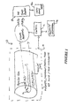
- FIGURE 1 illustrates schematically an MRI system 10 which includes the usual static magnet assembly, gradient coils, and transmit RF coils collectively denoted 12 under control of a processor 14, which typically communicates with an operator via a conventional keyboard/control workstation 16. These devices generally employ a system of multiple processors for carrying out specialized timing and other functions in the MRI system 10 as will be appreciated.
- an MRI image processor 18 receives digitized data representing RF NMR responses from an object region under examination (e.g., a human body 1) and, typically via multiple Fourier transformation processes well-known in the art, calculates a digitized visual image (e.g., a two-dimensional array of picture elements or pixels, each of which may have different gradations of gray values or color values, or the like) which is then conventionally displayed, or printed out, on a display 18a.
- a digitized visual image e.g., a two-dimensional array of picture elements or pixels, each of which may have different gradations of gray values or color values, or the like
- the apparatus is largely conventional.
- the basic RF data acquisition is modified, and subsequent signal processing altered, by providing a plurality of surface coils 20a, 20b...20i for simultaneous signal reception, along with corresponding signal processing and digitizing channels.
- the processor recombines the collected values into two or more spatial harmonics from which multiple lines of the signal matrix are developed. This recombination may be performed in real time as the data arrives, or after the fact via postprocessing as is convenient with the apparatus and the calibration information at hand.
- the magnetic resonance signal for a plane with spin density and coil sensitivity may be written as follows: where and as usual, with ⁇ the gyromagnetic ratio. and the magnitude of the x and y gradients, and and the times spent the in the x and y gradients, respectively.
- the spin excitation function as well as the effects of relaxation have been incorporated into a pulse-sequence-specific sensitivity function C .
- the symbol indicates a convolution.
- For regions of the sample in which the coil sensitivity is roughly homogeneous we may write and is equal to the spatial Fourier transform of the spin density function. Double Fourier transformation with respect to and reconstructs the usual spin-density image
- a k-space matrix of frequency-encoded and phase-encoded information is produced for the image plane of interest, with successive lines represented by broad horizontal line corresponding to a different phase-encoding gradient value.
- Each phase encoding step corresponds to a distinct spatial modulation and these spatial modulations are represented schematically by the curves at the left of the FIGURE.
- prior art magnetic resonance receiver coils do not have uniform sensitivity. Signals from different regions of the imaged volume produce different currents, in an RF coil, with the spatial variation in sensitivity being simply related to the inhomogeneity of RF field produced by the coil over the sample volume.
- sensitivity For a standard circular surface coil, there is a sensitivity "sweet spot" centered at roughly one diameter below the coil, with a monotonic falloff of sensitivity together with increasing phase differences in all directions.
- Traditional imaging protocols often position the receiving coil with the target tissue at its region of maximum sensitivity.
- the MR signal from these coils will have an information content somewhat different from that of the usual coil signal, and that by separating out one or more collected signals corresponding to pure spatial harmonics, these may be used to fill a larger portion of the data space than is conventionally done.
- a complex combination of cosinusoidal and sinusoidal sensitivity profiles yields where is the spatial frequency of the inhomogeneous coil sensitivity.
- the combined MR signal from the inhomogeneous coils is shifted in k -space by an amount
- This k -space shift has precisely the same form as the phase-encoding shift produced by evolution in a y gradient of magnitude
- SMASH exploits this realization to convert the signals collected in a set of surface coils into spatial harmonic signals, and fill multiple lines of k-space from each signal collection. If one such harmonic is generated in addition to the homogeneous signal (zero th harmonic) then one may then apply half as many y gradient steps to build up the full k -space matrix necessary for image acquisition. When higher harmonics of larger are added, the number of necessary y gradient steps is further reduced.
- the acquisition time is reduced by an integer factor of M+1 . If both positive and negative exponentials are used, an extra line appears at an interval above and below each gradient-encoded line.
- the k -space geometry of this acquisition strategy is illustrated in FIGURE 2A.
- Applicant further realized that the sensitivity of each individual coil in an array need not be strictly sinusoidal, so long as the net sensitivity of the array permits construction of harmonics having the desired sinusoidal shape.
- This realization significantly relaxes the constraints on coil design and disposition, and in conjunction with a calibration or normalization process, allows the signals from multiple coils with a wide range of shapes and geometries to be combined in several ways to yield net signals with multiple sinusoidal sensitivity profiles.
- FIGURE 2B illustrates geometry of the coil array and the image plane.
- a set of three adjacent coils are used with separate coil outputs in a surface array extending generally over the region and planes of interest.
- the patient is positioned and the spin preparation fields are applied to condition a plane P which, by way of example may intersect the patient's heart to image the blood vessels thereof, or which may intercept a region of the abdomen to image its contents.
- the coil array 20 is located above or below the region to be imaged, so that each coil 20a, 20b, 20c has at least some sensitivity to RF signals emanating from region P.
- the coils are each somewhat overlapped in the y-direction to minimize inductive coupling. As shown, they are overlapped at neighboring edges.
- Each coil viewed individually has a sensitivity function which is highest directly above or below the center of the coil, and which falls off with distance from the coil center.
- the signals from these coils are combined to produce several separate "virtual" or synthetic signals which each correspond to a pure spatial harmonic.
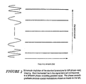
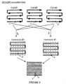
- FIGURE 3 demonstrates this situation schematically for a set of eight rectangular coils 20a, 20b,...20h laid end-to-end, with a slight overlap.
- each coil 20a, 20b... has a sensitivity curve a, b,... which rises to a broad peak directly under the coil and drops off substantially beyond the coil perimeter.
- the sum of the coil sensitivities forms a relatively constant sensitivity, over the full length of the array, corresponding to the zeroth spatial harmonic.
- the remaining lines (B)-(E) of FIGURE 3 illustrate recombining of different ones of these individual offset but otherwise identical coil sensitivity functions into a new synthetic sinusoidal spatial sensitivity.
- the net sensitivity profile is a linear combination of the intrinsic sensitivity profiles of the component coils.
- n j is the weighting coefficient of the j th coil sensitivity function C j (x,y) .
- the sensitivity profiles of RF surface coils are not simple Gaussian profiles but more complicated functions which are, in general, complex in the mathematical sense of having both real and imaginary components.
- the coil sensitivity functions must describe both the magnitudes and the phases of the signals produced by precessing spins at various distances from the coil center, and these magnitudes and phases vary according to the reciprocity relation where E( r ) is the voltage induced in a coil by a given voxel at position r , m ( r ) is the nuclear magnetic moment of the voxel, and is the xy vector component of the field generated at r by a unit current in the coil as described for example in D. I. Hoult and R. E. Richards, The signal-to-noise ratio of the nuclear magnetic resonance experiment . J. Magn. Reson. 24 , 71-85 (1976).
- the coil geometry for SMASH signal acquisition may be that of an MR phased array, as described in P. B. Roemer, W. A. Edelstein, C. E. Hayes, S. P. Souza, and O. M. Mueller, The NMR phased array .
- phased arrays which contain multiple inductively decoupled coils with some spatial separation, and which include separate receivers for independent collection of data from the coils.
- the technical problem of minimizing inductive coupling of such coils has been previously addressed for multiple-coil constructions in the context of phased-array MR imaging devices, and two basic strategies were developed.
- One strategy is to design a coil array with an appropriately chosen overlap of neighboring component coils to minimize inductive coupling.
- the second strategy involves the use of low input impedance preamplifiers on each component coil channel. Both of these features are advantageously applied in various embodiments of the present invention.
- a linear RF coil array as shown in FIGURE 2B was selected having a geometry suitable for spatial harmonic generation.
- This array was a cardiac imaging array having three eight-inch (200 mm) rectangular coils adjacent to each other.
- the appropriateness of the coil geometry was first tested in numerical simulations, using analytic integration of the Biot-Savart law to calculate the transverse field B 1 xy ( r ) of Eq. [6], and hence to model the sensitivity profile of each coil.
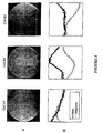
- FIGURE 4 For the phantom image technique a round water-filled dummy was suspended at the image plane used in the image acquisition above to provide a phantom image slice known to be of uniform spin density.
- Line (A) of FIGURE 4 shows the images a,b,c generated from the separate signal received in each of the respective coils 20a, 20b, 20c of FIGURE 2B, processed separately.
- Line (B) of FIGURE 4 shows the corresponding real and imaginary components of the coil sensitivity function determined from the detected signal, taken along the diameter A of the FIGURE.
- each spatial harmonic was represented as a linear combination of the three sensitivities. This was done as shown in FIGURE 4A.
- the real and imaginary components of the sensitivity function were normalized, yielding the component values a,b,c plotted at panels A and B, respectively, of FIGURE 4A.
- optimal weights for linear combination of component coil signals were determined by iterative fitting of the sensitivity data to the target spatial harmonic sensitivity profiles, with the complex weights serving as fitting parameters and the sum of absolute magnitude deviations from the target profile serving as a measure of goodness of fit.
- Panel C of FIGURE 4A shows the resulting best fit to the zero th harmonic, corresponding to uniform sensitivity.
- Panel D illustrates the best fit to the first spatial harmonic.
- Each was realized as a simple linear combination, with complex coefficients, of the three coil sensitivities shown in panels A and B.
- the stored coil signals received during each spin conditioning cycle of image acquisition were recombined with the weights as determined above into two distinct spatial harmonics, corresponding to two distinct k -space-shifted signals.
- the data sets were then interleaved, in the ordering sequence of FIGURE 2A , to yield the full k -space matrix.
- This matrix was double Fourier transformed in the conventional manner to give the reconstructed SMASH image.
- this data was reconstructed after the fact, i.e., post processed to both determine a suitable set of weights for forming the composite spatial harmonic sensitivities, and then to recombine the already measured signals with those weights into corresponding spatial harmonic measurement signals.
- the optimal weightings may be determined in advance with prior knowledge of the coil sensitivities, and the conversion of coil signals may be performed on-the-fly, that is, in real time.
- a simple controller attached to the coils may determine the appropriate weights, from a lookup table or by some other linear or non-linear interpolative mechanism, and then combine the signals to produce a separate composite signal corresponding to each spatial harmonic.
- a neural network may be used to "learn" the appropriate weighting.
- the sensitivity may be modeled with accuracy, rather than be empirically derived from normalizing the coil responses to a uniform sample. More generally, the process illustrated in FIGURES 4 and 4A may be used to determine suitable coefficients for a given image plane, and this process may be repeated to compile a table for each of many planes so that the apparatus need only look up the necessary weights in order to produce the desired composite signals for the plane of interest.
- reconstruction does not require a preliminary sensitivity measurement or an iterative fitting procedure, and simply involves a set of weighted sums. In either case, once the new composite signals are formed, the additional data must simply be entered at the correct matrix position, and the full matrix subjected to a fast Fourier transform.
- FIGURES 5 and 5A illustrate the k-space matrix construction for this prototype in more detail.
- Half the usual number of gradient steps with twice the usual spacing in k-space were applied, and the RF response was recorded in each of three coils.
- each of these RF responses corresponded to an image of half the desired field of view.
- the coil signals were then combined into two sets with different weightings to produce synthetic composite signals corresponding to the zero th and first harmonics, and the two synthesized responses were interleaved to fill alternating lines of the k-space matrix.
- the matrix was then Fourier transformed in a conventional way to form the image.
- the resulting image had full resolution over the full field of view.
- line (A) depicts the acquisition of signal in each component coil.
- a representative signal point P is picked up in each coil, and thus contributes to the line in k-space formed with each coil signal.
- Line (B) shows the processing performed in the prototype described above, according to which the coil signals are combined into a first set S 0 and a second set S 1 which each form different lines (even and odd as shown, corresponding to one gradient step separation) of the k-space matrix. These are combined at line (C) into the full matrix.
- FIGURE 5A illustrates corresponding images and signals
- Line (A) of that FIGURE shows the half field-of-view images a, b, c reconstructed from separate coil signals, of which the signals themselves are shown in line (B).
- Line (C) shows the two spatial harmonic signals and line (D) the full interleaved signal, or k-space matrix.
- Line (E) illustrates the image reconstructed from the signals of line (C).
- the middle three stages (B), (C) and (D) correspond directly to the steps shown schematically in FIGURE 5.
- FIGURES 6A, 6B and 7A, 7B respectively, show phantom and in vivo images formed by the three-coil prototype embodiment using the SMASH imaging technique.
- FIGURE 6A shows the proton-density image of a water-filled phantom, obtained using a TSE sequence (described further below) with a total conventional acquisition time of 10 seconds.
- FIGURE 6B shows the equivalent image obtained in 5 seconds with the SMASH processing. Apart from certain residual artifacts, the images have an identical appearance.
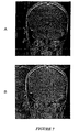
- FIGURES 7A and 7B show a reference and SMASH-reconstructed coronal image through the brain of a healthy adult volunteer, the images being acquired in 71 and 35 seconds, respectively. All these images were acquired using commercial hardware and a convenient pulse sequence with high spatial resolution and good SNR; a fifty percent acquisition time reduction was achieved. The acquisition time savings described here have also been shown to apply to other commercial machines and pulse sequences, including the fastest MR imaging machines and sequences. Some residual foldover artifacts are present in the SMASH reconstructed image, due to imperfections in the composite spatial harmonic sensitivity profiles. However, the prototype used an existing coil array designed for other purposes, and improvements both in coil design and in the accuracy of coil sensitivity mapping and spatial harmonic generation, are expected to minimize these artifacts.
- the phantom images of FIGURE 6A, B were generated as follows. First with the phantom centered over the coil array, data for the reference image were acquired in a 6 mm thick coronal slice parallel to and 80 mm above the plane of the array, using a turbo spin echo pulse sequence with five echoes per excitation. The field-of-view (FOV) was 200 mm, centered on the phantom, and matrix size was 256 x 256. Phase encoding was performed in the right-left direction (i.e. in the direction of the coil array), with a single signal average. Data from each of the three component coil channels was acquired simultaneously and, in the prototype, were stored separately for later processing. Acquisition time was measured at 10 seconds.
- FOV field-of-view
- a second coronal slice using the same technique and imaging parameters was taken to serve as a measure of component coil sensitivity. It was acquired 12 mm above the first one, in a region of uniform spin density in the phantom. Then, a third image at the same level as the first was obtained in half the time using twice the phase-encode step, and hence half the field of view, in the right-left direction. Matrix size was now 256 x 128. Acquisition time was 5 seconds, exactly half the time taken for the first image.
- the volunteer was positioned with his head above the coil array, and images were taken in the same plane and with the same parameters as for the phantom images, except that eight signal averages with a slice thickness of 10 mm were used to improve SNR.
- the coil sensitivity image from the phantom was also used as a sensitivity reference for the in vivo images.
- coil weightings were determined by fitting actual coil sensitivity data to the desired spatial harmonic sensitivities.
- the sensitivity function along the right-left diameter of the phantom was extracted from the component coil sensitivity reference images.
- the phantom spans the entire extent of each image, and since the sensitivity reference image plane intersects the phantom in a region of uniform spin density, these intensity profiles correspond precisely to the complex sensitivity functions of the coils along the diameter.
- the sensitivity of each component surface coil falls off monotonically with distance from the coil, and the phase shift grows with distance from the coil center.
- the reference images in FIGURES 6A AND 7A were formed by combining the component coil reference images pixel-by-pixel as the square root of the sum of square magnitudes.
- FIGURE 5A shows intermediate stages in SMASH reconstruction of the phantom image.
- the procedure for the in vivo image was identical.
- the three component coil signals ( B ) representing half-time, half-FOV aliased images ( A ) were combined into two composite signal sets, one for the zero th spatial harmonic and one for the first spatial harmonic ( C ).
- the two composite signal data sets were interleaved to form a data matrix of size 256 x 256 ( D ), This matrix was Fourier transformed to yield the reconstructed image ( E ), which is also shown in FIGURE 6B.
- the foregoing SMASH imaging technique may be applied with a great many of the known pulse sequences or spin conditioning techniques, and will in general share the advantages of the underlying sequential imaging methods which are used to collect partial k -space information.
- suitable spatial harmonics may be generated with a coil array
- the additional acquisition time savings afforded by SMASH reconstruction involves no significant sacrifice in resolution or SNR. This contrasts markedly with the trade-off in SNR or resolution that characterizes many existing approaches to fast imaging, such as low flip-angle sequences.
- FIGURES 6A, 6B Visual inspection of the phantom images in FIGURES 6A, 6B reveals a slight degradation in SNR in the SMASH reconstructed image as compared with the reference image. Part of this apparent loss may be traced to the residual foldover artifacts, in which some of the intensity of the primary image is "stolen" by aliased ghosts. There is another noteworthy difference between the SNR profiles of the two images, however.
- the reference image in FIGURE 6A was generated using a sum-of-squares combination of component coil images, as is described in PB. Roemer, W.A. Edelstein, C.E. Hayes, S.P. Souza, and O.M. Mueller, The NMR phased array . Magn. Reson. Med.
- SMASH reconstructions therefore, do away with intensity peaks in regions of component coil overlap in favor of a spatially homogeneous image profile.
- sensitivity-dependent linear combinations may be used independently of SMASH as a method of homogeneity correction.
- a homogeneity-corrected version of the image in FIGURE 6A may be generated by linear combination of component coil reference images, using the weights calculated for the zero th harmonic profile in FIGURE 4A.
- the SMASH imaging technique depends upon the measurement and manipulation of coil sensitivities for its spatial harmonic generation. Errors in spatial harmonics may lead to aliasing artifacts and SNR degradation (for example due to mismatch and mixing between the spatial frequency components of the image). This raises several practical issues. First, we must be able to estimate coil sensitivities with some reasonable degree of accuracy. Sensitivity maps from phantom images were used for the SMASH reconstructions presented here. As noted above, numerical simulations of coil sensitivity may also be used, if these simulations have been reliably calibrated. The invention has also implemented use of other techniques for direct sensitivity estimation, including in vivo estimation using fast low resolution scans at the time of in vivo imaging. Low-pass-filtering of images could also be used to provide sensitivity maps. These techniques may be . automated for calibrating, normalizing and deriving weights for creating the composite signals.
- B 0 and B 1 magnetic field inhomogeneities may distort the true coil sensitivity profiles and interfere with spatial harmonic generation.
- Spin echo sequences like the TSE sequence used in this work, have the advantage of refocusing static field inhomogeneities.
- Gradient echo sequences have been found to perform just as well.
- the weight-finding algorithm used by applicant automatically compensated for some degree of residual field inhomogeneity and generated accurate spatial harmonics even in the presence of systematic phase or intensity errors.
- the technique has been found to be directly applicable not only to spin echo sequences such as TSE but also to several variants of gradient echo sequences including FISP and standard GRE.
- the geometry of the coil array will place certain limitations on the field of view (FOV), the position, and the angulation of image planes suitable for SMASH reconstruction.
- FOV field of view
- Surface coil sensitivity profiles vary with distance from the coil center, and while simulations indicate that a wide range of image plane geometries are compatible with SMASH reconstruction, the reconstruction may begin to fail at large distances and angles, where sensitivity functions become broad and asymmetric.
- SMASH contemplates the use of coil arrays with multiple component coils extending in more than one linear direction.
- a two-dimensional array such as an N ⁇ M rectangular array, will allow generation of spatial harmonics along multiple directions and will relax constraints on image plane position and angulation.
- Wraparound arrays are also contemplated to allow spatial harmonic generation in a plane transverse to the body plane.
- a coil arrangement with a surface array on the top of thew body and another surface array on the bottom, possibly with some linear offset with respect to one another, will allow fine tuning of spatial harmonics in a plane between the two and will have the added advantage of increasing overall SNR in such a plane.
- An extended grid coil grid coil may also be designed with a sensitivity profile more closely approximating a sinusoid.
- the component coils in these arrays may be overlapped and may be output to low input impedance preamplifiers as necessary, to minimize inductive coupling. It is also possible that the simple expedient of transforming the coil sensitivities to achieve the spatial harmonic reconstruction procedure of SMASH may be applied in large arrays of coils of the sort proposed by MR Hutchinson and Raff in 1988 and described further byKwiat, Einav and Navon, supra.
- the SMASH technique as applied to a conventional NMR apparatus described above partially replaces gradient phase encoding by a spatial encoding procedure tied to the detection coils, in which some of the spatial modulations that distinguish different phase-encoding lines are generated by combining signals from multiple coils arrayed above or around the imaging volume.
- This shift of responsibility from gradient geometry to coil geometry, and from the spin preparation stage to the stage of signal detection and combination allows for simultaneous acquisition of multiple lines of k -space. Enhancement of image speed, resolution or field of view by a factor of two, five, ten or more may be expected with appropriate coil arrays generating sufficient harmonics.
- SMASH has a number of practical advantages as a fast imaging scheme. As a partially parallel acquisition strategy, it can be combined with most existing sequential fast imaging techniques for multiplicative time savings. No special hardware is required, other than an appropriate coil array.
- One embodiment of SMASH includes a coil array together with a digital signal processor configured to combine the outputs of the component coils with appropriate weights as described above, and produce two or more output signals, each of which represents a composite spatial harmonic as described above.
- the array with processor may then be directly substituted for a conventional receiving coil, with the difference that it produces two or more lines of data for each spin preparation cycle of the MRI apparatus.
- the plug-in coil unit may operate with older MRI devices to directly enhance the acquisition time, field of view, or resolution by a factor of two or more, without changing the expensive magnet and other spin preparation hardware of the device.
- SMASH may be performed on machines not equipped with much more costly magnetic enhancements such as EPI gradient systems.
- Combination of the component coil signals may be performed after the fact, allowing for a wide range of postprocessing steps, including fine tuning of spatial harmonics, adaptive artifact correction, or, like in the present invention, non-Fourier wavelet encoding and reconstruction.
- the invention may include a digital signal processor or neural network processor in addition to the normal complement of control and processing assemblies to evaluate the responses or coil signals and carry out the signal combination into spatial harmonics in real time. Even in the simplest examples, spatial harmonic reconstructions automatically yield a homogeneous intensity profile for the reconstructed image, and this may be advantageous for some imaging applications.
- the time gained in a SMASH acquisition may be used to collect extra data for better spatial resolution and/or SNR, or else faster acquisitions may be used to eliminate motion artifacts from mobile structures in the field of view
- the SMASH technique has been described above with reference to a prototype embodiment which produces signals corresponding to spatial harmonics that yield additional k-space lines equivalent to the conventional gradient steps in a Fourier transform imaging system and a simple coil array and processing assembly for enhancing image speed, quality or field.
- the method according to the present invention is directed to coils and processors for producing wavelet spatial representations to replace, supplement or enhance MR imaging processes and systems.
Landscapes
- Physics & Mathematics (AREA)
- Condensed Matter Physics & Semiconductors (AREA)
- General Physics & Mathematics (AREA)
- Health & Medical Sciences (AREA)
- General Health & Medical Sciences (AREA)
- Nuclear Medicine, Radiotherapy & Molecular Imaging (AREA)
- Radiology & Medical Imaging (AREA)
- Engineering & Computer Science (AREA)
- Signal Processing (AREA)
- High Energy & Nuclear Physics (AREA)
- Electromagnetism (AREA)
- Magnetic Resonance Imaging Apparatus (AREA)
Priority Applications (1)
| Application Number | Priority Date | Filing Date | Title |
|---|---|---|---|
| EP02011913A EP1243938A3 (en) | 1996-11-12 | 1997-11-05 | Ultra-fast MR imaging with radiofrequency coil arrays (SMASH) |
Applications Claiming Priority (3)
| Application Number | Priority Date | Filing Date | Title |
|---|---|---|---|
| US746358 | 1996-11-12 | ||
| US08/746,358 US5910728A (en) | 1996-11-12 | 1996-11-12 | Simultaneous acquisition of spatial harmonics (SMASH): ultra-fast imaging with radiofrequency coil arrays |
| PCT/US1997/020068 WO1998021600A1 (en) | 1996-11-12 | 1997-11-05 | Simultaeous acquisition of spatial harmonics (smash): ultra-fast imaging with radiofrequency coil arrays |
Related Child Applications (1)
| Application Number | Title | Priority Date | Filing Date |
|---|---|---|---|
| EP02011913A Division EP1243938A3 (en) | 1996-11-12 | 1997-11-05 | Ultra-fast MR imaging with radiofrequency coil arrays (SMASH) |
Publications (2)
| Publication Number | Publication Date |
|---|---|
| EP1015903A1 EP1015903A1 (en) | 2000-07-05 |
| EP1015903B1 true EP1015903B1 (en) | 2003-06-11 |
Family
ID=25000500
Family Applications (2)
| Application Number | Title | Priority Date | Filing Date |
|---|---|---|---|
| EP02011913A Withdrawn EP1243938A3 (en) | 1996-11-12 | 1997-11-05 | Ultra-fast MR imaging with radiofrequency coil arrays (SMASH) |
| EP97948164A Expired - Lifetime EP1015903B1 (en) | 1996-11-12 | 1997-11-05 | Simultaneous acquisition of spatial basis functions: ultra-fast imaging with radiofrequency coil arrays |
Family Applications Before (1)
| Application Number | Title | Priority Date | Filing Date |
|---|---|---|---|
| EP02011913A Withdrawn EP1243938A3 (en) | 1996-11-12 | 1997-11-05 | Ultra-fast MR imaging with radiofrequency coil arrays (SMASH) |
Country Status (7)
| Country | Link |
|---|---|
| US (1) | US5910728A (enExample) |
| EP (2) | EP1243938A3 (enExample) |
| JP (1) | JP4044145B2 (enExample) |
| AU (1) | AU5428698A (enExample) |
| DE (1) | DE69722827T2 (enExample) |
| ES (1) | ES2201331T3 (enExample) |
| WO (1) | WO1998021600A1 (enExample) |
Families Citing this family (147)
| Publication number | Priority date | Publication date | Assignee | Title |
|---|---|---|---|---|
| US6289232B1 (en) * | 1998-03-30 | 2001-09-11 | Beth Israel Deaconess Medical Center, Inc. | Coil array autocalibration MR imaging |
| US6223065B1 (en) * | 1998-04-15 | 2001-04-24 | Medrad, Inc. | Automatic coil element selection in large MRI coil arrays |
| US6144873A (en) * | 1998-04-17 | 2000-11-07 | Board Of Trustees Of The Leland Stanford Junior University | Method of efficient data encoding in dynamic magnetic resonance imaging |
| US6134465A (en) * | 1998-06-12 | 2000-10-17 | General Electric Company | Method for reducing artifacts in MR image acquired with phased array surface coil |
| EP1014102A3 (en) | 1998-12-24 | 2001-10-04 | Marconi Electronic Systems Limited | Multislice magnetic resonance imaging using an array of receiving coils |
| DE19901171C2 (de) * | 1999-01-14 | 2001-12-13 | Axel Haase | Verfahren und Vorrichtung zum Gewinnen von Daten für Magnetresonanz-Bildgebung |
| WO2000064344A1 (en) * | 1999-04-22 | 2000-11-02 | The Johns Hopkins University | Cardiac motion tracking using cine harmonic phase (harp) magnetic resonance imaging |
| EP1101126A1 (en) * | 1999-05-20 | 2001-05-23 | Koninklijke Philips Electronics N.V. | Magnetic resonance imaging method with sub-sampling |
| EP1101127A1 (en) * | 1999-05-20 | 2001-05-23 | Koninklijke Philips Electronics N.V. | Magnetic resonance imaging method with sub-sampling |
| US6680610B1 (en) * | 1999-05-24 | 2004-01-20 | Walid E. Kyriakos | Apparatus and method for parallel MR data acquisition and parallel image reconstruction from multiple receiver coil arrays for fast MRI |
| JP2003500138A (ja) * | 1999-05-24 | 2003-01-07 | キリアコス,ワリッド,イー. | Mriコイル配列からの平行したデータ収集のための方法と装置 |
| JP4632535B2 (ja) | 2000-12-27 | 2011-02-16 | 株式会社東芝 | Mri装置 |
| US6801800B2 (en) * | 1999-11-29 | 2004-10-05 | Kabushiki Kaisha Toshiba | MR imaging using ECG-prep scan |
| US6907280B2 (en) * | 1999-12-02 | 2005-06-14 | The General Hospital Corporation | Method and apparatus for objectively measuring pain, pain treatment and other related techniques |
| US6476606B2 (en) * | 1999-12-03 | 2002-11-05 | Johns Hopkins University | Method for parallel spatial encoded MRI and apparatus, systems and other methods related thereto |
| JP3952247B2 (ja) * | 1999-12-08 | 2007-08-01 | 株式会社日立メディコ | 核磁気共鳴撮影装置 |
| US6597935B2 (en) | 2000-02-10 | 2003-07-22 | The Johns Hopkins University | Method for harmonic phase magnetic resonance imaging |
| GB2360094A (en) * | 2000-03-06 | 2001-09-12 | Marconi Caswell Ltd | RF screens for MRI |
| US6611143B2 (en) | 2000-03-14 | 2003-08-26 | Kabushiki Kaisha Toshiba | MRI apparatus generating odd and/or even echo images with sensitivity distribution of coils |
| US6717406B2 (en) | 2000-03-14 | 2004-04-06 | Beth Israel Deaconess Medical Center, Inc. | Parallel magnetic resonance imaging techniques using radiofrequency coil arrays |
| EP1212633A1 (en) * | 2000-03-24 | 2002-06-12 | Koninklijke Philips Electronics N.V. | Magnetic resonance imaging method with sub-sampling |
| US6469505B1 (en) * | 2000-03-31 | 2002-10-22 | Ge Medical Systems Global Technology Co., Llc | Method and apparatus to reduce perturbation field effects in MR images by restricting the region of interest |
| EP1307759A1 (en) * | 2000-07-31 | 2003-05-07 | Koninklijke Philips Electronics N.V. | Magnetic resonance method for forming a fast dynamic imaging |
| EP1307758A1 (en) * | 2000-07-31 | 2003-05-07 | Koninklijke Philips Electronics N.V. | Magnetic resonance method for forming a fast dynamic image |
| JP4502488B2 (ja) * | 2000-09-25 | 2010-07-14 | ジーイー・メディカル・システムズ・グローバル・テクノロジー・カンパニー・エルエルシー | 磁気共鳴撮影装置 |
| WO2002042791A1 (en) * | 2000-11-24 | 2002-05-30 | Koninklijke Philips Electronics N.V. | Method for obtaining mri images using sub-sampling in a vertical field mri apparatus |
| DE10059772A1 (de) * | 2000-11-30 | 2002-06-13 | Philips Corp Intellectual Pty | MR-Bildrekonstruktion |
| US6477470B2 (en) | 2000-12-01 | 2002-11-05 | Pgs Americas, Inc. | Method and system for deghosting |
| US6556009B2 (en) * | 2000-12-11 | 2003-04-29 | The United States Of America As Represented By The Department Of Health And Human Services | Accelerated magnetic resonance imaging using a parallel spatial filter |
| US6823205B1 (en) * | 2001-02-08 | 2004-11-23 | Boston University Radiology Associates | Synthetic images for a magnetic resonance imaging scanner using linear combination of source images to generate contrast and spatial navigation |
| DE10106830C2 (de) | 2001-02-14 | 2003-01-16 | Siemens Ag | Verfahren zur Bilderzeugung mittels magnetischer Resonanz mit mehreren unabhängigen Empfangsantennen |
| WO2002077659A1 (en) | 2001-03-23 | 2002-10-03 | Koninklijke Philips Electronics N.V. | Magnetic resonance imaging method for an angulated cut plane |
| US6771070B2 (en) * | 2001-03-30 | 2004-08-03 | Johns Hopkins University | Apparatus for magnetic resonance imaging having a planar strip array antenna including systems and methods related thereto |
| US6841998B1 (en) | 2001-04-06 | 2005-01-11 | Mark Griswold | Magnetic resonance imaging method and apparatus employing partial parallel acquisition, wherein each coil produces a complete k-space datasheet |
| US6738501B2 (en) * | 2001-04-13 | 2004-05-18 | Ge Medical Systems Global Technology Co., Llc | Adaptive data differentiation and selection from multi-coil receiver to reduce artifacts in reconstruction |
| US6549799B2 (en) | 2001-04-18 | 2003-04-15 | Sunnybrook And Women's College Health Sciences Centre | Concurrent MRI of multiple objects |
| US6675034B2 (en) * | 2001-04-19 | 2004-01-06 | Sunnybrook And Women's Health Sciences Centre | Magnetic resonance imaging using direct, continuous real-time imaging for motion compensation |
| US6915152B2 (en) | 2001-04-19 | 2005-07-05 | General Electric Company | Method for MR imaging with an array of RF coils |
| DE10119660B4 (de) * | 2001-04-20 | 2006-01-05 | Siemens Ag | Verfahren zur schnellen Gewinnung eines Magnetresonanzbildes |
| GB2374673A (en) * | 2001-04-20 | 2002-10-23 | Marconi Medical Systems Uk Ltd | Magnetic Resonance Imaging |
| GB2374672A (en) * | 2001-04-20 | 2002-10-23 | Marconi Medical Systems Uk Ltd | Magnetic Resonance Imaging |
| US6714010B2 (en) * | 2001-04-20 | 2004-03-30 | Brigham And Women's Hospital, Inc. | Combining unfold with parallel magnetic resonance imaging |
| GB2380549A (en) * | 2001-04-20 | 2003-04-09 | Marconi Medical Systems Uk Ltd | Magnetic Resonance Imaging |
| US7283859B2 (en) * | 2001-04-20 | 2007-10-16 | Brigham And Womens' Hospital, Inc. | Artifact suppression in dynamic magnetic resonance imaging |
| GB2374674A (en) * | 2001-04-20 | 2002-10-23 | Marconi Medical Systems Uk Ltd | Magnetic Resonance Imaging |
| US6559642B2 (en) * | 2001-05-09 | 2003-05-06 | Ge Medical Systems Global Technology Company, Llc | Calibration method for use with sensitivity encoding MRI acquisition |
| US6900635B1 (en) | 2001-06-08 | 2005-05-31 | General Electric Company | Head RF quadrature coil array for parallel imaging |
| US6975115B1 (en) * | 2001-06-08 | 2005-12-13 | Ge Medical Systems Global Technology Company, Llc | Coil arrays for parallel imaging in magnetic resonance imaging |
| US6930480B1 (en) | 2001-06-08 | 2005-08-16 | General Electric Company | Head coil arrays for parallel imaging in magnetic resonance imaging |
| RU2313102C2 (ru) * | 2001-08-21 | 2007-12-20 | Конинклейке Филипс Электроникс Н.В. | Устройство магнитного резонанса с антенной системой возбуждения |
| DE10144654B4 (de) * | 2001-09-11 | 2005-02-17 | Siemens Ag | Gerät und Verfahren zur Magnet-Resonanz-Bildgebung unter Verwendung einer verbesserten parallelen Akquisition |
| DE10148445A1 (de) * | 2001-10-01 | 2003-04-30 | Siemens Ag | Signalauswerteverfahren für Magnetresonanz-Empfangssignale und hiermit korrespondierende Empfangsanordnung |
| DE10152734B4 (de) * | 2001-10-25 | 2005-12-29 | Siemens Ag | Gerät und Verfahren zur Magnet-Resonanz-Bildgebung bei gleichzeitiger Messung zweier benachbarter Schichten |
| US6584337B2 (en) | 2001-11-21 | 2003-06-24 | General Electric Company | Method and system for extended volume imaging using MRI |
| WO2003046597A1 (en) | 2001-11-26 | 2003-06-05 | Koninklijke Philips Electronics N.V. | Magnetic resonance imaging method with reduced acoustic noise |
| US6492814B1 (en) | 2001-12-21 | 2002-12-10 | General Electric Company | Self localizing receive coils for MR |
| DE10163815A1 (de) * | 2001-12-22 | 2003-07-03 | Philips Intellectual Property | Paralleles MR-Bildgebungsverfahren |
| AU2002353183A1 (en) * | 2001-12-31 | 2003-07-24 | The Johns Hopkins University School Of Medicine | Mri tunable antenna and system |
| US6683454B2 (en) * | 2002-03-28 | 2004-01-27 | Ge Medical Systems Global Technology Company, Llc | Shifting of artifacts by reordering of k-space |
| WO2003085412A1 (en) * | 2002-04-08 | 2003-10-16 | Koninklijke Philips Electronics N.V. | Data-processing to form a compound object data set from a plurality of basis datasets |
| US7418287B2 (en) * | 2002-05-13 | 2008-08-26 | Koninklijke Philips Electronics N.V. | Magnetic resonance imaging method with accelerated data acquisition |
| US7005853B2 (en) | 2002-05-13 | 2006-02-28 | Koninklijke Philips Electronics N.V. | Prior-information-enhanced dynamic magnetic resonance imaging |
| AU2003224374A1 (en) * | 2002-05-13 | 2003-11-11 | Koninklijke Philips Electronics N.V. | Reduction of susceptibility artifacts in subencoded single-shot magnetic resonance imaging |
| EP1506422A1 (en) * | 2002-05-13 | 2005-02-16 | Koninklijke Philips Electronics N.V. | Magnetic resonance imaging method |
| US6963768B2 (en) * | 2002-05-16 | 2005-11-08 | General Electric Company | Whole body MRI scanning with moving table and interactive control |
| US6707300B2 (en) * | 2002-05-17 | 2004-03-16 | Ge Medical Systems Global Technology Co., Llc | Gradient non-linearity compensation in moving table MRI |
| DE10226488A1 (de) | 2002-06-14 | 2003-12-24 | Philips Intellectual Property | MR-Anordnung mit unterschiedlich optimierten Hochfrequenzspulenarrays |
| US6791321B2 (en) * | 2002-06-18 | 2004-09-14 | Koninklijke Philips Electronics N.V. | Birdcage coils for simultaneous acquisition of spatial harmonics |
| DE10231061A1 (de) * | 2002-07-10 | 2004-01-22 | Philips Intellectual Property & Standards Gmbh | Verfahren und System zur Verbesserung des Informationsgehaltes in einem Bild |
| JP3869337B2 (ja) * | 2002-08-20 | 2007-01-17 | ジーイー・メディカル・システムズ・グローバル・テクノロジー・カンパニー・エルエルシー | 磁気共鳴撮影装置 |
| US7009396B2 (en) | 2002-09-12 | 2006-03-07 | General Electric Company | Method and system for extended volume imaging using MRI with parallel reception |
| US6833700B2 (en) * | 2002-09-13 | 2004-12-21 | General Electric Company | Method and apparatus for reconstruction of images in parallel MRI systems |
| US6980002B1 (en) | 2002-11-04 | 2005-12-27 | General Electric Company | Integrated cervical-thoracic-lumbar spine MRI array coil |
| EP1567880A1 (en) * | 2002-11-26 | 2005-08-31 | Koninklijke Philips Electronics N.V. | Determination of subencoding mri coil sensitivities in a lower order magnetic field |
| US7429860B2 (en) * | 2003-01-28 | 2008-09-30 | University Of Southern California | Noise reduction for spectroscopic signal processing |
| DE10313004B3 (de) * | 2003-03-24 | 2005-01-20 | Siemens Ag | Verfahren zur Modenbildung, Verfahren zur Modenbereitstellung und Empfangseinheit für ein Magnetresonanzgerät |
| DE10318682B4 (de) * | 2003-04-24 | 2011-12-29 | Peter M. Jakob | Beschleunigte Magnet-Resonanz-Bildgebung im Rahmen der parallelen Akquisition von MRT-Daten |
| US7078899B2 (en) * | 2003-05-15 | 2006-07-18 | Case Western Reserve University | Pareto-optimal magnetic resonance data acquisition |
| US6781374B1 (en) | 2003-05-27 | 2004-08-24 | General Electric Company | Systems and methods for simultaneous acquisition of spatial harmonics |
| US6876199B2 (en) * | 2003-05-30 | 2005-04-05 | General Electric Company | Method and system for accelerated imaging using parallel MRI |
| US6919722B2 (en) * | 2003-10-09 | 2005-07-19 | Ge Medical Systems Global Technology Company, Llc | Image quality improvement for SENSE with low signal regions |
| US7109710B2 (en) * | 2003-10-17 | 2006-09-19 | General Electric Company | Method and apparatus to improve signal-to-noise ratio without compromising field-of-view for simultaneous MR data acquisition by an array of RF coils of an MR scanner |
| EP1709459A1 (en) * | 2004-01-15 | 2006-10-11 | Koninklijke Philips Electronics N.V. | Coil sensitivity estimation for parallel imaging |
| WO2005081973A2 (en) * | 2004-02-22 | 2005-09-09 | Medrad, Inc. | Head coil and neurovascular array for parallel imaging capable magnetic resonance systems |
| US7741846B2 (en) * | 2004-06-28 | 2010-06-22 | Koninklijke Philips Electronics N.V. | Parallel magnetic resonance imaging |
| WO2006029240A2 (en) * | 2004-09-03 | 2006-03-16 | Invivo Corporation | Technique for parallel mri imaging (k-t grappa) |
| US7397242B2 (en) | 2005-10-27 | 2008-07-08 | Wisconsin Alumni Research Foundation | Parallel magnetic resonance imaging method using a radial acquisition trajectory |
| US7583082B1 (en) * | 2006-04-19 | 2009-09-01 | University Of Virginia Patent Foundation | Partially parallel magnetic resonance imaging using arbitrary k-space trajectories with image reconstruction based on successive convolution operations |
| US7279893B1 (en) * | 2006-04-20 | 2007-10-09 | General Electric Company | Receiver channel data combining in parallel mr imaging |
| US7741842B2 (en) * | 2006-04-25 | 2010-06-22 | The Board Of Trustees Of The Leland Stanford Junior University | Calibration maps for parallel imaging free of chemical shift artifact |
| US7468605B2 (en) * | 2006-04-25 | 2008-12-23 | The Board Of Trustees Of The Leland Stanford Junior University | Simultaneous chemical species separation and T2* measurement using MRI |
| US7508211B2 (en) * | 2006-04-25 | 2009-03-24 | The Board Of Trustees Of The Leland Stanford Junior University | Regularized species separation |
| US7486073B2 (en) | 2006-04-25 | 2009-02-03 | The Board Of Trustees Of The Leland Stanford Junior University | Sliding window reconstruction and phase/field map updating for dynamic chemical shift imaging |
| US7592807B2 (en) * | 2006-04-25 | 2009-09-22 | The Board Of Trustees Of The Leland Stanford Junior University | Maximum likelihood estimator in the presence of non-identically distributed noise for decomposition of chemical species in MRI |
| US7592810B2 (en) | 2006-04-25 | 2009-09-22 | The Board Of Trustees Of The Leland Stanford Junior University | MRI methods for combining separate species and quantifying a species |
| US7486074B2 (en) * | 2006-04-25 | 2009-02-03 | The Board Of Trustees Of The Leland Stanford Junior University | Self-calibration methods for parallel imaging and multipoint water-fat separation methods |
| US7336074B2 (en) * | 2006-05-05 | 2008-02-26 | Quality Electrodynamics | Active decoupling of MRI RF transmit coils |
| US7439739B2 (en) * | 2006-07-11 | 2008-10-21 | The Board Of Trustees Of The Leland Stanford Junior University | Anti-aliased magnetic resonance image reconstruction using partially parallel encoded data |
| US7375523B1 (en) * | 2006-10-30 | 2008-05-20 | General Electric Company | System and method for fast MR coil sensitivity mapping |
| DE102007004620B4 (de) * | 2007-01-30 | 2010-02-04 | Siemens Ag | Verbessertes dreidimensionales schichtselektives Mehrschicht-Anregungsverfahren in der MRT-Bildgebung |
| US7777487B2 (en) * | 2007-02-15 | 2010-08-17 | Uwm Research Foundation, Inc. | Methods and apparatus for joint image reconstruction and coil sensitivity estimation in parallel MRI |
| US7888935B1 (en) | 2007-02-23 | 2011-02-15 | University Of Virginia Patent Foundation | K-space trajectory estimation in spiral MRI system and related method thereof |
| US8306289B1 (en) | 2007-02-23 | 2012-11-06 | University Of Virginia Patent Foundation | Method and system for off-resonance correction for non-cartesian parallel image reconstruction |
| US8219176B2 (en) * | 2007-03-08 | 2012-07-10 | Allegheny-Singer Research Institute | Single coil parallel imaging |
| US7907760B2 (en) * | 2007-03-08 | 2011-03-15 | Allegheny-Singer Research Institute | Single coil parallel imaging |
| US7541808B2 (en) * | 2007-04-11 | 2009-06-02 | Allegheny-Singer Research Institute | Rapid MRI dynamic imaging using MACH |
| US7394252B1 (en) | 2007-05-03 | 2008-07-01 | The General Hospital Corporation | Regularized GRAPPA reconstruction |
| US20090093709A1 (en) * | 2007-05-18 | 2009-04-09 | Beth Israel Deaconess Medical Center, Inc. | Noise reduction system and methods for magnetic resonance imaging |
| US20080292167A1 (en) * | 2007-05-24 | 2008-11-27 | Nick Todd | Method and system for constrained reconstruction applied to magnetic resonance temperature mapping |
| US7817838B2 (en) * | 2007-05-24 | 2010-10-19 | University Of Utah Research Foundation | Method and system for constrained reconstruction of imaging data using data reordering |
| US7816918B2 (en) * | 2007-05-24 | 2010-10-19 | The Johns Hopkins University | Optimized MRI strip array detectors and apparatus, systems and methods related thereto |
| US8519708B2 (en) * | 2007-11-06 | 2013-08-27 | T2 Biosystems, Inc. | Small magnet and RF coil for magnetic resonance relaxometry |
| US8441259B2 (en) * | 2007-12-12 | 2013-05-14 | Koninklijke Philips Electronics N.V. | Transmit/receive coil for ultra-high field MRI |
| JP5443695B2 (ja) * | 2008-03-05 | 2014-03-19 | 株式会社東芝 | 磁気共鳴イメージング装置 |
| US7977943B2 (en) * | 2008-04-10 | 2011-07-12 | General Electric Company | Method and system for reconstructing images |
| US7592808B1 (en) * | 2008-05-06 | 2009-09-22 | General Electric Company | System and method for reducing MR scan time using partial fourier acquisition and compressed sensing |
| US8688193B2 (en) * | 2008-06-26 | 2014-04-01 | Allegheny-Singer Research Institute | Magnetic resonance imager, method and program which continuously applies steady-state free precession to k-space |
| US8131046B2 (en) * | 2008-10-29 | 2012-03-06 | Allegheny-Singer Research Institute | Magnetic resonance imager using cylindrical offset region of excitation, and method |
| US8299793B2 (en) * | 2009-01-12 | 2012-10-30 | Mayo Foundation For Medical Education And Research | Method and apparatus for improving 2D acceleration in MRI using a new coil array design |
| EP2230530A1 (en) * | 2009-03-20 | 2010-09-22 | Koninklijke Philips Electronics N.V. | A tesseral shim coil for a magnetic resonance system |
| DE102009015885B4 (de) * | 2009-04-01 | 2011-06-16 | Siemens Aktiengesellschaft | Verfahren zur Detektion fehlerhafter MR-Daten und Magnetresonanzanlage |
| US8198892B2 (en) * | 2009-04-22 | 2012-06-12 | Allegheny-Singer Research Institute | Steady-state-free-precession (SSFP) magnetic resonance imaging (MRI) and method |
| US8405394B2 (en) * | 2009-10-20 | 2013-03-26 | Allegheny-Singer Research Institute | Targeted acquisition using holistic ordering (TACHO) approach for high signal to noise imaging |
| FR2951835B1 (fr) * | 2009-10-26 | 2013-10-18 | Bruker Biospin | Dispositif de correction de signaux de consigne et systeme de generation de gradients comportant un tel dispositif |
| US8427153B2 (en) * | 2010-01-15 | 2013-04-23 | Beth Israel Deaconess Medical Center, Inc. | Method for motion correction in magnetic resonance imaging using radio frequency coil arrays |
| US20110215805A1 (en) * | 2010-03-03 | 2011-09-08 | Allegheny-Singer Research Institute | MRI and method using multi-slice imaging |
| DE102010011968A1 (de) * | 2010-03-03 | 2011-09-08 | Universität Duisburg-Essen | Verfahren zur Erzeugung eines Bilds mit einem Magnetresonanztomographen |
| DE102011077197B4 (de) * | 2011-06-08 | 2013-05-16 | Siemens Aktiengesellschaft | Verzeichnungskorrektur bei einer Magnetresonanz-Bildgebung |
| US8659297B2 (en) * | 2012-02-27 | 2014-02-25 | Perinatronics Medical Systems, Inc. | Reducing noise in magnetic resonance imaging using conductive loops |
| KR101310825B1 (ko) | 2012-05-10 | 2013-10-14 | 고려대학교 산학협력단 | 자기 공명 영상 생성 방법 및 그에 따른 자기 공명 영상 생성 장치 |
| KR101330638B1 (ko) | 2012-05-10 | 2013-11-18 | 고려대학교 산학협력단 | 자기 공명 영상 생성 방법 및 그에 따른 자기 공명 영상 생성 장치 |
| CN104880684B (zh) * | 2014-02-28 | 2019-02-22 | 西门子(深圳)磁共振有限公司 | 一种磁共振成像系统的图像重建方法和装置 |
| CN105738846B (zh) * | 2014-12-12 | 2019-01-25 | 西门子(深圳)磁共振有限公司 | K空间数据采集方法及其磁共振成像方法 |
| DE102015200695B4 (de) | 2015-01-19 | 2016-08-18 | Siemens Healthcare Gmbh | Generieren von Steuerinformationen für eine Magnetresonanz-Bildgebung unter Verwendung mehrerer Frequenzspektren von verschiedenen Spulenelementen |
| US10076249B2 (en) | 2015-08-04 | 2018-09-18 | General Electric Company | Proton density and T1 weighted zero TE MR thermometry |
| KR101697872B1 (ko) * | 2015-10-20 | 2017-01-18 | 한국과학기술원 | 자기 공명 영상에서의 고스트 아티팩트를 제거하는 방법 및 이를 위한 자기 공명 장치 |
| US10852373B2 (en) | 2016-09-21 | 2020-12-01 | Quality Electrodynamics, Llc | Modulating magnetic resonance imaging transmit field in magnetic resonance fingerprinting using single layer transmit/receive radio frequency coil |
| US10386430B2 (en) | 2016-09-21 | 2019-08-20 | Quality Electrodynamics, Llc | Single layer magnetic resonance imaging transmit/receive radio frequency coil |
| US11156682B2 (en) | 2017-03-24 | 2021-10-26 | Quality Electrodynamics, Llc | Single layer magnetic resonance imaging transmit/receive radio frequency coil for different anatomies |
| US10976388B2 (en) | 2017-03-24 | 2021-04-13 | Quality Electrodynamics, Llc | Minimizing intravascular magnetic resonance imaging (MRI) guidewire heating with single layer MRI transmit/receive radio frequency coil |
| US10649048B2 (en) | 2017-04-28 | 2020-05-12 | Quality Electrodynamics, Llc | Single layer magnetic resonance imaging (MRI) transmit/receive (TX/RX) radio frequency (RF) coil with integrated shimming |
| US11193992B2 (en) | 2017-05-05 | 2021-12-07 | Quality Electrodynamics, Llc | Single layer magnetic resonance imaging (MRI) transmit/receive (Tx/Rx) radio frequency (RF) coil with induced current failsafe protection |
| US10838028B2 (en) | 2017-06-19 | 2020-11-17 | Quality Electrodynamics, Llc | Decoupling magnetic resonance imaging (MRI) radio frequency (RF) coil elements with high acceleration factor in parallel transmit (pTx) or receive (Rx) coils using fewer channels |
| US11402448B2 (en) | 2019-02-28 | 2022-08-02 | Quality Electrodynamics, Llc | Magnetic resonance imaging coil with significantly fewer number of baluns |
| US11852707B2 (en) * | 2019-10-21 | 2023-12-26 | Shanghai United Imaging Healthcare Co., Ltd. | Systems and methods for simultaneous multi-slice magnetic resonance imaging |
| US11899085B2 (en) | 2019-10-21 | 2024-02-13 | Shanghai United Imaging Healthcare Co., Ltd. | System and method for magnetic resonance imaging |
| US11555875B2 (en) | 2021-03-24 | 2023-01-17 | Coilone, LLC | RF receive coil circuit for MRI systems |
Citations (1)
| Publication number | Priority date | Publication date | Assignee | Title |
|---|---|---|---|---|
| EP0412824A2 (en) * | 1989-08-09 | 1991-02-13 | Kabushiki Kaisha Toshiba | Magnetic resonance imaging system |
Family Cites Families (6)
| Publication number | Priority date | Publication date | Assignee | Title |
|---|---|---|---|---|
| US4825162A (en) * | 1987-12-07 | 1989-04-25 | General Electric Company | Nuclear magnetic resonance (NMR) imaging with multiple surface coils |
| US4857846A (en) * | 1988-03-31 | 1989-08-15 | The Regents Of The University Of California | Rapid MRI using multiple receivers producing multiply phase-encoded data derived from a single NMR response |
| US5086275A (en) * | 1990-08-20 | 1992-02-04 | General Electric Company | Time domain filtering for nmr phased array imaging |
| US5185573A (en) * | 1991-04-16 | 1993-02-09 | Hewlett-Packard Company | Method for focusing of magnetic resonance images |
| US5374890A (en) * | 1992-07-24 | 1994-12-20 | Picker International, Inc. | Simultaneous magnetic resonance imaging of multiple human organs |
| US5469060A (en) * | 1993-08-19 | 1995-11-21 | Meyerand; Mary E. | Time encoded magnetic resonance imaging |
-
1996
- 1996-11-12 US US08/746,358 patent/US5910728A/en not_active Expired - Lifetime
-
1997
- 1997-11-05 WO PCT/US1997/020068 patent/WO1998021600A1/en not_active Ceased
- 1997-11-05 EP EP02011913A patent/EP1243938A3/en not_active Withdrawn
- 1997-11-05 ES ES97948164T patent/ES2201331T3/es not_active Expired - Lifetime
- 1997-11-05 EP EP97948164A patent/EP1015903B1/en not_active Expired - Lifetime
- 1997-11-05 JP JP52262798A patent/JP4044145B2/ja not_active Expired - Fee Related
- 1997-11-05 DE DE69722827T patent/DE69722827T2/de not_active Expired - Fee Related
- 1997-11-05 AU AU54286/98A patent/AU5428698A/en not_active Abandoned
Patent Citations (1)
| Publication number | Priority date | Publication date | Assignee | Title |
|---|---|---|---|---|
| EP0412824A2 (en) * | 1989-08-09 | 1991-02-13 | Kabushiki Kaisha Toshiba | Magnetic resonance imaging system |
Also Published As
| Publication number | Publication date |
|---|---|
| US5910728A (en) | 1999-06-08 |
| ES2201331T3 (es) | 2004-03-16 |
| EP1243938A3 (en) | 2003-01-08 |
| WO1998021600A1 (en) | 1998-05-22 |
| EP1243938A2 (en) | 2002-09-25 |
| DE69722827T2 (de) | 2004-05-06 |
| JP2001503662A (ja) | 2001-03-21 |
| AU5428698A (en) | 1998-06-03 |
| EP1015903A1 (en) | 2000-07-05 |
| DE69722827D1 (de) | 2003-07-17 |
| JP4044145B2 (ja) | 2008-02-06 |
Similar Documents
| Publication | Publication Date | Title |
|---|---|---|
| EP1015903B1 (en) | Simultaneous acquisition of spatial basis functions: ultra-fast imaging with radiofrequency coil arrays | |
| WO1998021600A9 (en) | Simultaeous acquisition of spatial harmonics (smash): ultra-fast imaging with radiofrequency coil arrays | |
| Sodickson et al. | Simultaneous acquisition of spatial harmonics (SMASH): fast imaging with radiofrequency coil arrays | |
| US6289232B1 (en) | Coil array autocalibration MR imaging | |
| US6326786B1 (en) | Magnetic resonance imaging method and apparatus | |
| US9983284B2 (en) | MRI with dixon-type water/fat separation and prior knowledge about inhomogeneity of the main magnetic field | |
| US5561370A (en) | Artefact suppression in GRASE Mr imaging | |
| CN105143906B (zh) | 金属抗mr成像 | |
| US7319324B2 (en) | MRI method and apparatus using PPA image reconstruction | |
| US20130127460A1 (en) | Mr imaging using navigators | |
| WO2014195384A1 (en) | Parallel mri with b0 distortion correction and multi-echo dixon water-fat separation using regularised sense reconstruction | |
| CN109219757A (zh) | Dixon型水/脂肪分离MR成像 | |
| US8320646B2 (en) | MRI acquisition using 2D sense and partial fourier pace sampling | |
| CN1190572A (zh) | 减少快速自旋回波磁共振图象中麦克斯韦项假象的方法 | |
| US7197353B2 (en) | Sensitivity encoding MRI acquisition method | |
| WO2019162198A1 (en) | Dixon mr imaging using a multi-gradient-echo sequence | |
| EP3931588A1 (en) | Epi mr imaging with distortion correction | |
| US11543482B2 (en) | Magnetic resonance imaging using motion-compensated image reconstruction | |
| EP1372110A2 (en) | Method and system for image reconstruction | |
| JP2002248089A (ja) | 磁気共鳴イメージング装置および方法 | |
| JP7559763B2 (ja) | ウェーブ符号化を用いたパラレルmrイメージング | |
| EP4012434A1 (en) | Dixon-type water/fat separation mr imaging | |
| CN113544526B (zh) | 使用波编码的并行mr成像 | |
| WO2019063574A1 (en) | DIXON TYPE WATER / GREASE SEPARATION MAGNETIC RESONANCE IMAGING WITH ENHANCED FAT OFFSET CORRECTION |
Legal Events
| Date | Code | Title | Description |
|---|---|---|---|
| PUAI | Public reference made under article 153(3) epc to a published international application that has entered the european phase |
Free format text: ORIGINAL CODE: 0009012 |
|
| 17P | Request for examination filed |
Effective date: 19990611 |
|
| AK | Designated contracting states |
Kind code of ref document: A1 Designated state(s): CH DE ES FR GB IT LI NL |
|
| 17Q | First examination report despatched |
Effective date: 20010802 |
|
| RAP1 | Party data changed (applicant data changed or rights of an application transferred) |
Owner name: BETH ISRAEL DEACONESS MEDICAL CENTER, INC. |
|
| GRAG | Despatch of communication of intention to grant |
Free format text: ORIGINAL CODE: EPIDOS AGRA |
|
| RTI1 | Title (correction) |
Free format text: SIMULTANEOUS ACQUISITION OF SPATIAL BASIS FUNCTIONS: ULTRA-FAST IMAGING WITH RADIOFREQUENCY COIL ARRAYS |
|
| GRAG | Despatch of communication of intention to grant |
Free format text: ORIGINAL CODE: EPIDOS AGRA |
|
| GRAH | Despatch of communication of intention to grant a patent |
Free format text: ORIGINAL CODE: EPIDOS IGRA |
|
| GRAH | Despatch of communication of intention to grant a patent |
Free format text: ORIGINAL CODE: EPIDOS IGRA |
|
| GRAA | (expected) grant |
Free format text: ORIGINAL CODE: 0009210 |
|
| AK | Designated contracting states |
Designated state(s): CH DE ES FR GB IT LI NL |
|
| REG | Reference to a national code |
Ref country code: GB Ref legal event code: FG4D |
|
| REG | Reference to a national code |
Ref country code: CH Ref legal event code: EP |
|
| REF | Corresponds to: |
Ref document number: 69722827 Country of ref document: DE Date of ref document: 20030717 Kind code of ref document: P |
|
| REG | Reference to a national code |
Ref country code: CH Ref legal event code: NV Representative=s name: LEMAN CONSULTING S.A. |
|
| REG | Reference to a national code |
Ref country code: ES Ref legal event code: FG2A Ref document number: 2201331 Country of ref document: ES Kind code of ref document: T3 |
|
| ET | Fr: translation filed | ||
| PLBE | No opposition filed within time limit |
Free format text: ORIGINAL CODE: 0009261 |
|
| STAA | Information on the status of an ep patent application or granted ep patent |
Free format text: STATUS: NO OPPOSITION FILED WITHIN TIME LIMIT |
|
| 26N | No opposition filed |
Effective date: 20040312 |
|
| PGFP | Annual fee paid to national office [announced via postgrant information from national office to epo] |
Ref country code: NL Payment date: 20071124 Year of fee payment: 11 Ref country code: ES Payment date: 20071126 Year of fee payment: 11 |
|
| PGFP | Annual fee paid to national office [announced via postgrant information from national office to epo] |
Ref country code: IT Payment date: 20071128 Year of fee payment: 11 Ref country code: CH Payment date: 20071129 Year of fee payment: 11 |
|
| PGFP | Annual fee paid to national office [announced via postgrant information from national office to epo] |
Ref country code: GB Payment date: 20071128 Year of fee payment: 11 Ref country code: FR Payment date: 20071119 Year of fee payment: 11 |
|
| PGFP | Annual fee paid to national office [announced via postgrant information from national office to epo] |
Ref country code: DE Payment date: 20071221 Year of fee payment: 11 |
|
| REG | Reference to a national code |
Ref country code: CH Ref legal event code: PL |
|
| GBPC | Gb: european patent ceased through non-payment of renewal fee |
Effective date: 20081105 |
|
| PG25 | Lapsed in a contracting state [announced via postgrant information from national office to epo] |
Ref country code: NL Free format text: LAPSE BECAUSE OF NON-PAYMENT OF DUE FEES Effective date: 20090601 |
|
| NLV4 | Nl: lapsed or anulled due to non-payment of the annual fee |
Effective date: 20090601 |
|
| PG25 | Lapsed in a contracting state [announced via postgrant information from national office to epo] |
Ref country code: IT Free format text: LAPSE BECAUSE OF NON-PAYMENT OF DUE FEES Effective date: 20081105 |
|
| REG | Reference to a national code |
Ref country code: FR Ref legal event code: ST Effective date: 20090731 |
|
| PG25 | Lapsed in a contracting state [announced via postgrant information from national office to epo] |
Ref country code: LI Free format text: LAPSE BECAUSE OF NON-PAYMENT OF DUE FEES Effective date: 20081130 Ref country code: DE Free format text: LAPSE BECAUSE OF NON-PAYMENT OF DUE FEES Effective date: 20090603 Ref country code: CH Free format text: LAPSE BECAUSE OF NON-PAYMENT OF DUE FEES Effective date: 20081130 |
|
| PG25 | Lapsed in a contracting state [announced via postgrant information from national office to epo] |
Ref country code: GB Free format text: LAPSE BECAUSE OF NON-PAYMENT OF DUE FEES Effective date: 20081105 |
|
| REG | Reference to a national code |
Ref country code: ES Ref legal event code: FD2A Effective date: 20081106 |
|
| PG25 | Lapsed in a contracting state [announced via postgrant information from national office to epo] |
Ref country code: ES Free format text: LAPSE BECAUSE OF NON-PAYMENT OF DUE FEES Effective date: 20081106 |
|
| PG25 | Lapsed in a contracting state [announced via postgrant information from national office to epo] |
Ref country code: FR Free format text: LAPSE BECAUSE OF NON-PAYMENT OF DUE FEES Effective date: 20081130 |