EP1015741B1 - Procede de traitement des gaz d'echappement d'un moteur a combustion interne et ligne d'echappement associee - Google Patents
Procede de traitement des gaz d'echappement d'un moteur a combustion interne et ligne d'echappement associee Download PDFInfo
- Publication number
- EP1015741B1 EP1015741B1 EP99906304A EP99906304A EP1015741B1 EP 1015741 B1 EP1015741 B1 EP 1015741B1 EP 99906304 A EP99906304 A EP 99906304A EP 99906304 A EP99906304 A EP 99906304A EP 1015741 B1 EP1015741 B1 EP 1015741B1
- Authority
- EP
- European Patent Office
- Prior art keywords
- monoliths
- monolith
- gases
- group
- exhaust
- Prior art date
- Legal status (The legal status is an assumption and is not a legal conclusion. Google has not performed a legal analysis and makes no representation as to the accuracy of the status listed.)
- Expired - Lifetime
Links
Images

Classifications
-
- A—HUMAN NECESSITIES
- A61—MEDICAL OR VETERINARY SCIENCE; HYGIENE
- A61Q—SPECIFIC USE OF COSMETICS OR SIMILAR TOILETRY PREPARATIONS
- A61Q19/00—Preparations for care of the skin
- A61Q19/06—Preparations for care of the skin for countering cellulitis
-
- A—HUMAN NECESSITIES
- A61—MEDICAL OR VETERINARY SCIENCE; HYGIENE
- A61K—PREPARATIONS FOR MEDICAL, DENTAL OR TOILETRY PURPOSES
- A61K8/00—Cosmetics or similar toiletry preparations
- A61K8/18—Cosmetics or similar toiletry preparations characterised by the composition
- A61K8/30—Cosmetics or similar toiletry preparations characterised by the composition containing organic compounds
- A61K8/60—Sugars; Derivatives thereof
- A61K8/602—Glycosides, e.g. rutin
-
- A—HUMAN NECESSITIES
- A61—MEDICAL OR VETERINARY SCIENCE; HYGIENE
- A61K—PREPARATIONS FOR MEDICAL, DENTAL OR TOILETRY PURPOSES
- A61K8/00—Cosmetics or similar toiletry preparations
- A61K8/18—Cosmetics or similar toiletry preparations characterised by the composition
- A61K8/30—Cosmetics or similar toiletry preparations characterised by the composition containing organic compounds
- A61K8/64—Proteins; Peptides; Derivatives or degradation products thereof
- A61K8/66—Enzymes
-
- F—MECHANICAL ENGINEERING; LIGHTING; HEATING; WEAPONS; BLASTING
- F01—MACHINES OR ENGINES IN GENERAL; ENGINE PLANTS IN GENERAL; STEAM ENGINES
- F01N—GAS-FLOW SILENCERS OR EXHAUST APPARATUS FOR MACHINES OR ENGINES IN GENERAL; GAS-FLOW SILENCERS OR EXHAUST APPARATUS FOR INTERNAL COMBUSTION ENGINES
- F01N13/00—Exhaust or silencing apparatus characterised by constructional features ; Exhaust or silencing apparatus, or parts thereof, having pertinent characteristics not provided for in, or of interest apart from, groups F01N1/00 - F01N5/00, F01N9/00, F01N11/00
- F01N13/009—Exhaust or silencing apparatus characterised by constructional features ; Exhaust or silencing apparatus, or parts thereof, having pertinent characteristics not provided for in, or of interest apart from, groups F01N1/00 - F01N5/00, F01N9/00, F01N11/00 having two or more separate purifying devices arranged in series
- F01N13/0097—Exhaust or silencing apparatus characterised by constructional features ; Exhaust or silencing apparatus, or parts thereof, having pertinent characteristics not provided for in, or of interest apart from, groups F01N1/00 - F01N5/00, F01N9/00, F01N11/00 having two or more separate purifying devices arranged in series the purifying devices are arranged in a single housing
-
- F—MECHANICAL ENGINEERING; LIGHTING; HEATING; WEAPONS; BLASTING
- F01—MACHINES OR ENGINES IN GENERAL; ENGINE PLANTS IN GENERAL; STEAM ENGINES
- F01N—GAS-FLOW SILENCERS OR EXHAUST APPARATUS FOR MACHINES OR ENGINES IN GENERAL; GAS-FLOW SILENCERS OR EXHAUST APPARATUS FOR INTERNAL COMBUSTION ENGINES
- F01N3/00—Exhaust or silencing apparatus having means for purifying, rendering innocuous, or otherwise treating exhaust
- F01N3/08—Exhaust or silencing apparatus having means for purifying, rendering innocuous, or otherwise treating exhaust for rendering innocuous
- F01N3/10—Exhaust or silencing apparatus having means for purifying, rendering innocuous, or otherwise treating exhaust for rendering innocuous by thermal or catalytic conversion of noxious components of exhaust
- F01N3/18—Exhaust or silencing apparatus having means for purifying, rendering innocuous, or otherwise treating exhaust for rendering innocuous by thermal or catalytic conversion of noxious components of exhaust characterised by methods of operation; Control
- F01N3/20—Exhaust or silencing apparatus having means for purifying, rendering innocuous, or otherwise treating exhaust for rendering innocuous by thermal or catalytic conversion of noxious components of exhaust characterised by methods of operation; Control specially adapted for catalytic conversion ; Methods of operation or control of catalytic converters
- F01N3/2053—By-passing catalytic reactors, e.g. to prevent overheating
-
- F—MECHANICAL ENGINEERING; LIGHTING; HEATING; WEAPONS; BLASTING
- F01—MACHINES OR ENGINES IN GENERAL; ENGINE PLANTS IN GENERAL; STEAM ENGINES
- F01N—GAS-FLOW SILENCERS OR EXHAUST APPARATUS FOR MACHINES OR ENGINES IN GENERAL; GAS-FLOW SILENCERS OR EXHAUST APPARATUS FOR INTERNAL COMBUSTION ENGINES
- F01N3/00—Exhaust or silencing apparatus having means for purifying, rendering innocuous, or otherwise treating exhaust
- F01N3/08—Exhaust or silencing apparatus having means for purifying, rendering innocuous, or otherwise treating exhaust for rendering innocuous
- F01N3/10—Exhaust or silencing apparatus having means for purifying, rendering innocuous, or otherwise treating exhaust for rendering innocuous by thermal or catalytic conversion of noxious components of exhaust
- F01N3/24—Exhaust or silencing apparatus having means for purifying, rendering innocuous, or otherwise treating exhaust for rendering innocuous by thermal or catalytic conversion of noxious components of exhaust characterised by constructional aspects of converting apparatus
- F01N3/28—Construction of catalytic reactors
- F01N3/2839—Arrangements for mounting catalyst support in housing, e.g. with means for compensating thermal expansion or vibration
- F01N3/2842—Arrangements for mounting catalyst support in housing, e.g. with means for compensating thermal expansion or vibration specially adapted for monolithic supports, e.g. of honeycomb type
-
- F—MECHANICAL ENGINEERING; LIGHTING; HEATING; WEAPONS; BLASTING
- F01—MACHINES OR ENGINES IN GENERAL; ENGINE PLANTS IN GENERAL; STEAM ENGINES
- F01N—GAS-FLOW SILENCERS OR EXHAUST APPARATUS FOR MACHINES OR ENGINES IN GENERAL; GAS-FLOW SILENCERS OR EXHAUST APPARATUS FOR INTERNAL COMBUSTION ENGINES
- F01N3/00—Exhaust or silencing apparatus having means for purifying, rendering innocuous, or otherwise treating exhaust
- F01N3/08—Exhaust or silencing apparatus having means for purifying, rendering innocuous, or otherwise treating exhaust for rendering innocuous
- F01N3/10—Exhaust or silencing apparatus having means for purifying, rendering innocuous, or otherwise treating exhaust for rendering innocuous by thermal or catalytic conversion of noxious components of exhaust
- F01N3/24—Exhaust or silencing apparatus having means for purifying, rendering innocuous, or otherwise treating exhaust for rendering innocuous by thermal or catalytic conversion of noxious components of exhaust characterised by constructional aspects of converting apparatus
- F01N3/28—Construction of catalytic reactors
- F01N3/2882—Catalytic reactors combined or associated with other devices, e.g. exhaust silencers or other exhaust purification devices
- F01N3/2885—Catalytic reactors combined or associated with other devices, e.g. exhaust silencers or other exhaust purification devices with exhaust silencers in a single housing
-
- F—MECHANICAL ENGINEERING; LIGHTING; HEATING; WEAPONS; BLASTING
- F01—MACHINES OR ENGINES IN GENERAL; ENGINE PLANTS IN GENERAL; STEAM ENGINES
- F01N—GAS-FLOW SILENCERS OR EXHAUST APPARATUS FOR MACHINES OR ENGINES IN GENERAL; GAS-FLOW SILENCERS OR EXHAUST APPARATUS FOR INTERNAL COMBUSTION ENGINES
- F01N1/00—Silencing apparatus characterised by method of silencing
- F01N1/08—Silencing apparatus characterised by method of silencing by reducing exhaust energy by throttling or whirling
- F01N1/089—Silencing apparatus characterised by method of silencing by reducing exhaust energy by throttling or whirling using two or more expansion chambers in series
Definitions
- the present invention relates to the field of gas treatment exhaust from an internal combustion engine.
- the invention relates to the catalytic depollution of these exhaust gas.
- the temperature levels are lower but a lower catalytic efficiency can be encountered because the catalyst does not operate continuously in the temperature range best suited to the depollution system used.
- US Patent 5,377,486 is an example.
- a first monolith called “light-off” or “priming” is located near the engine outlet, a main monolith located downstream of it.
- the first monolith is only supplied with exhaust gas starting the engine, as long as the exhaust gases are still too high cold to hope for the activation of the main monolith.
- this first monolith is however effective quickly and partially compensates for the inactivity of the monolith main at startup. When the gases get hot enough, piloted winnowing prevents gas from passing through the first monolith, they go directly to the main monolith which has action. It is thus a question of preserving the catalyst of "light-off”.
- Document JP-08 189344 thus discloses a winnowing according to the temperature of the gases leaving the engine.
- the present invention indeed proposes to limit the temperature to level of the catalyst (s) present in the exhaust line in fractionating the catalyst and partially cooling the gases exhaust between each fraction of the catalyst.
- the subject of the present invention is an exhaust line of internal combustion engine comprising a line having a first end connected to the motor outlet and comprising several monoliths or groups of monoliths intended for the catalytic conversion of gases exhaust arranged in series in said pipe and separated from each other others by empty spaces.
- said line further comprises means intended for permanently pass a first part of the gases exhaust only through at least one of said monoliths or group of monoliths and the second part of the exhaust gases through all monoliths, which limits temperature spikes supported by said monoliths and / or to operate them in a determined temperature range, (compare with JP-A-04 140 413).
- the first monolith or group of monoliths includes several monoliths arranged in series and separated by empty spaces of monolith.
- said line exhaust includes first and second monoliths and a conduit allowing the first part of the gas not to pass into the first monolith and go directly to the second monolith after have been remixed with the second part of the gas which has passed in the first monolith.
- the second group of monoliths includes several monoliths arranged in series and separated by empty spaces of monolith.
- the exhaust line according to the invention can be characterized by a first and second monoliths arranged in a housing in which opens a second end of said pipe with a portion which protrudes into said housing, openings being provided in the portion protruding so that some of the gases escape before reaching the first monolith, and a means arranged in said casing making it possible to direct all of the gases through the second monolith.
- the first monolith is placed at the end of the protruding part of the pipe.
- the second monolith can be arranged on a wall of separation of the housing into two volumes so that it defines the unique means of passage of the exhaust gases from the first volume to the second volume.
- the invention also relates to a method for treating gases.
- exhaust from an internal combustion engine consisting in making them pass successively through several monoliths or a group of monoliths intended for their catalytic conversion.
- a first part of said gases through a first monolith or group of monoliths then through a space without monoliths then through a second monolith or group of monoliths and in that the second part gas does not pass through the first monolith or group of monoliths, in order to limit the temperature peaks supported by said monoliths and / or operate them within a temperature range determined.
- the method uses a third monolith or group of monoliths arranged downstream of the second monolith, the second part of the gases is mixed with the first part of the gases leaving the second monolith and the mixture is introduced at the inlet of the third monolith or group of monoliths.
- said line exhaust 1 may include a first monolith 5 or group of monoliths and a second monolith 10.
- a conduit 110 derives a first part of the gas leaving conduit 1 according to arrows A, which does not pass not in the first monolith 5 and is remixed in volume 7 with the second part of the exhaust gases which, in turn, is passed according to arrows B in the first monolith 5.
- This mixing is carried out upstream of the second monolith 10 so that all the gas can pass through it before to be released into the atmosphere. No winnowing system is planned.
- the proportion of gas which does not pass into the first monolith 5 is a function the overall gas flow of the dimensioning and the orientation of the "bypass" 110.
- Figure 2 shows more precisely an exhaust line having a conduit 1 which leaves the engine.
- Line 1 is divided, upstream of the first monolith 5 so that a first part of the exhaust gases follows the arrows A, through a bypass 110 of the first monolith 5.
- the second part of the exhaust gas passes through the first monolith 5, according to the arrow B.
- the two parts of the gas flow meet upstream of the second monolith 10, in an empty space 7.
- the mixture thus enters thus on the second monolith 10 and in comes out through a pipe 9 which also opens into the atmosphere.
- the advantage of the invention lies in that the first part of the gases, which does not pass through the first monolith 5, does not contribute to any catalytic reaction occurring in this monolith. We thus obtain as a first effect, a limitation of the temperature in the monolith 5. In addition, the first part of the gases remains cooler than the second part which, for its part, was warmed by its passage in the first monolith 5. The mixture of the two parts of the exhaust gas in the volume 7 will therefore make it possible to obtain a gas having a temperature less excessive input of the second monolith 10, and this permanently. It is thus possible to limit the maximum operating temperature of the monoliths and limit the risks of degradation thereof.
- Another advantage of the process according to the invention is that it does not include no controlled winnowing system and therefore requires no sensor additional in the exhaust line.
- the proportion of gas passing bypass 110 depends in particular on the overall gas flow exhaust, their temperature and the geometry of this duct 110 which can also be adapted according to the application concerned.
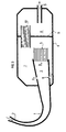
- FIG. 3 A second example of application of the invention is presented on the figure 3.
- This type of exhaust line used for example for two-stroke engine, includes line 1 having a first end 2 connected to the motor output (not shown); at its second end 3 the pipe leads, according to this embodiment of the invention, into a casing 4 which usually serves as a silencer. Specifically, driving 1 protrudes over a certain length inside the casing 4. At the end 3 a first monolith 5 is placed intended for the catalytic conversion of exhaust gas.
- the casing 4 contains a partition wall 6 which defines two volumes; the first 7 contains the end 3 of the pipe 1 and the first monolith 5.
- the second volume 8 of the casing 4 includes the opening 9 for the outlet of the exhaust gases decontaminated towards the atmosphere.
- openings 11 in the pipe 1 are provided near the second end 3; the openings 11 are carried out in the protruding portion of line 1 so that the gases which pass through the openings 11 are systematically found in the first volume 7.
- a first part of the gases escapes through said openings according to arrows A, without undergoing any catalytic reaction, therefore without undergoing a temperature increase.
- the second part of the gases is directed according to arrow B through the first monolith 5, then enters the mixing volume 7. The temperature of this second part of the gases will increase due to the reactions catalysts produced in the first monolith 5.
- the present invention finds its preferred application in cases where exhaust gas temperatures are very high and can cause deterioration of the catalyst support or performance catalyst.
- the invention can thus limit the temperature peaks observed in catalytic cleanup systems for ignition engines controlled and two-stroke engines.
Landscapes
- Chemical & Material Sciences (AREA)
- Engineering & Computer Science (AREA)
- Health & Medical Sciences (AREA)
- Chemical Kinetics & Catalysis (AREA)
- Life Sciences & Earth Sciences (AREA)
- Combustion & Propulsion (AREA)
- Mechanical Engineering (AREA)
- General Engineering & Computer Science (AREA)
- Public Health (AREA)
- Animal Behavior & Ethology (AREA)
- General Health & Medical Sciences (AREA)
- Toxicology (AREA)
- Veterinary Medicine (AREA)
- Birds (AREA)
- Epidemiology (AREA)
- Dermatology (AREA)
- Exhaust Gas After Treatment (AREA)
Description
- La figure 1 est un schéma général du principe de l'invention;
- La figure 2 est une coupe schématisée d'un mode de réalisation de l'invention;
- La figure 3 est un schéma d'un autre mode de réalisation de l'invention.
Claims (8)
- Ligne d'échappement de moteur à combustion interne comprenant une conduite (1) ayant une première extrémité (2) reliée à la sortie du moteur et comprenant au moins un premier et un deuxième monolithes ou groupes de monolithes destinés à la conversion catalytique des gaz d'échappement, disposés en série dans ladite conduite et séparés les uns des autres par des espaces vides, comprenant en outre un moyen (110 ; 11) destiné à faire passer de façon permanente une première partie des gaz d'échappement uniquement à travers l'un au moins desdits monolithes ou groupe de monolithes (10) et la seconde partie des gaz d'échappement à travers tous les monolithes (5, 10) afin de limiter les pics de température supportés par lesdits monolithes et/ou de les faire fonctionner dans une plage de température déterminée, caractérisée en ce que le premier monolithe ou groupe de monolithes (5) comprend plusieurs monolithes disposés en série et séparés par des espaces vides de monolithes.
- Ligne d'échappement selon la revendication 1, caractérisée en ce qu'elle comprend un conduit (110) permettant à la première partie du gaz de ne pas passer dans le premier groupe de monolithe (5) et d'accéder directement au deuxième monolithe (10) après avoir été mélangée avec la seconde partie du gaz qui, elle, est passée dans le premier groupe de monolithes (5).
- Ligne d'échappement selon l'une quelconque des revendications 1 ou 2, caractérisée en ce que le deuxième groupe de monolithes (10) comprend plusieurs monolithes disposés en série et séparés par des espaces vides de monolithes.
- Ligne d'échappement selon la revendication 1, caractérisée en ce que le premier (5) et le deuxième (10) monolithes sont disposés dans un carter (4) dans lequel débouche une deuxième extrémité (3) de ladite conduite (1) avec une portion qui dépasse dans ledit carter (4), des ouvertures (11) étant prévues dans la portion dépassante afin qu'une partie des gaz s'en échappe avant d'atteindre le premier monolithe (5), et un moyen (6) est disposé dans ledit carter (4) permettant de diriger la totalité des gaz à travers le deuxième monolithe (10).
- Ligne d'échappement selon la revendication 4, caractérisée en ce que le premier monolithe (5) est placé à l'extrémité (3) de la partie dépassante de la conduite (1).
- Ligne d'échappement selon l'une quelconque des revendications 4 ou 5, caractérisée en ce que le deuxième monolithe (10) est disposé sur une paroi de séparation (6) du carter (4) en deux volumes (7, 8) de telle façon qu'il définisse l'unique moyen de passage des gaz d'échappement du premier volume (7) vers le deuxième volume (8).
- Procédé de traitement des gaz d'échappement issus d'un moteur à combustion interne consistant à les faire passer successivement à travers plusieurs monolithes ou groupe de monolithes destinés à leur conversion catalytique, et consistant en ce qu'on fait passer en permanence une première partie desdits gaz à travers un premier monolithe ou groupe de monolithes puis à travers un espace sans monolithes puis à travers un deuxième monolithe ou groupe de monolithes et en ce que la seconde partie des gaz ne passe pas à travers le premier monolithe ou groupe de monolithes, afin de limiter les pics de température supportés par lesdits monolithes et/ou de les faire fonctionner dans une plage de température déterminée, caractérisé en ce que le premier monolithe ou groupe de monolithes comprend plusieurs monolithes disposés en série et séparés par des espaces vides de monolithe.
- Procédé de traitement selon la revendication 7, caractérisé en ce qu'il utilise un troisième monolithe ou groupe de monolithe disposé en aval du deuxième monolithe, en ce que la deuxième partie des gaz est mélangée à la première partie des gaz qui sortent du deuxième monolithe et le mélange est introduit à l'entrée du troisième monolithe ou groupe de monolithes.
Applications Claiming Priority (3)
| Application Number | Priority Date | Filing Date | Title |
|---|---|---|---|
| FR9802439A FR2775498B1 (fr) | 1998-02-27 | 1998-02-27 | Procede de traitement des gaz d'echappement d'un moteur a combustion interne et ligne d'echappement associee |
| FR9802439 | 1998-02-27 | ||
| PCT/FR1999/000432 WO1999043934A1 (fr) | 1998-02-27 | 1999-02-25 | Procede de traitement des gaz d'echappement d'un moteur a combustion interne et ligne d'echappement associee |
Publications (2)
| Publication Number | Publication Date |
|---|---|
| EP1015741A1 EP1015741A1 (fr) | 2000-07-05 |
| EP1015741B1 true EP1015741B1 (fr) | 2003-05-21 |
Family
ID=9523482
Family Applications (1)
| Application Number | Title | Priority Date | Filing Date |
|---|---|---|---|
| EP99906304A Expired - Lifetime EP1015741B1 (fr) | 1998-02-27 | 1999-02-25 | Procede de traitement des gaz d'echappement d'un moteur a combustion interne et ligne d'echappement associee |
Country Status (5)
| Country | Link |
|---|---|
| EP (1) | EP1015741B1 (fr) |
| JP (1) | JP2001522436A (fr) |
| DE (1) | DE69908074T2 (fr) |
| FR (1) | FR2775498B1 (fr) |
| WO (1) | WO1999043934A1 (fr) |
Families Citing this family (5)
| Publication number | Priority date | Publication date | Assignee | Title |
|---|---|---|---|---|
| JP2003155926A (ja) | 2001-11-21 | 2003-05-30 | Cataler Corp | 排気ガス浄化装置 |
| JP4643290B2 (ja) * | 2005-01-31 | 2011-03-02 | ジーエルサイエンス株式会社 | 微小流量の流体制御方法及び装置 |
| US7347046B2 (en) * | 2005-05-27 | 2008-03-25 | Yamaha Hatsudoki Kabushiki Kaisha | Layout of catalyst of vehicle |
| KR102084991B1 (ko) * | 2018-06-25 | 2020-03-05 | 삼성중공업 주식회사 | 유체 유입 차단 구조 |
| CN111365102A (zh) * | 2020-04-21 | 2020-07-03 | 天纳克(苏州)排放系统有限公司 | 尾气后处理封装 |
Family Cites Families (9)
| Publication number | Priority date | Publication date | Assignee | Title |
|---|---|---|---|---|
| FR2097624A5 (fr) | 1970-07-16 | 1972-03-03 | Peugeot & Renault | |
| JPH02173312A (ja) * | 1988-12-26 | 1990-07-04 | Mazda Motor Corp | 触媒コンバータ |
| JPH04140413A (ja) * | 1990-10-01 | 1992-05-14 | Yamaha Motor Co Ltd | 内燃機関の排気ガス浄化装置 |
| JP2850551B2 (ja) * | 1991-02-15 | 1999-01-27 | トヨタ自動車株式会社 | 内燃機関の排気浄化装置 |
| JP3200772B2 (ja) * | 1992-03-30 | 2001-08-20 | ヤマハ発動機株式会社 | 内燃機関用触媒付きマフラー |
| US5377486A (en) | 1993-05-17 | 1995-01-03 | Ford Motor Company | Catalytic converter system |
| JP3685809B2 (ja) * | 1993-09-28 | 2005-08-24 | 本田技研工業株式会社 | エンジンの排気浄化装置 |
| JPH08189344A (ja) | 1995-01-12 | 1996-07-23 | Fuji Oozx Inc | 排気ガスの浄化制御装置 |
| GB2313796A (en) * | 1996-06-08 | 1997-12-10 | Ford Motor Co | Catalytic converter for a lean burn engine |
-
1998
- 1998-02-27 FR FR9802439A patent/FR2775498B1/fr not_active Expired - Fee Related
-
1999
- 1999-02-25 DE DE69908074T patent/DE69908074T2/de not_active Expired - Fee Related
- 1999-02-25 JP JP54323599A patent/JP2001522436A/ja not_active Ceased
- 1999-02-25 EP EP99906304A patent/EP1015741B1/fr not_active Expired - Lifetime
- 1999-02-25 WO PCT/FR1999/000432 patent/WO1999043934A1/fr active IP Right Grant
Also Published As
| Publication number | Publication date |
|---|---|
| DE69908074T2 (de) | 2003-11-27 |
| WO1999043934A1 (fr) | 1999-09-02 |
| EP1015741A1 (fr) | 2000-07-05 |
| FR2775498A1 (fr) | 1999-09-03 |
| DE69908074D1 (de) | 2003-06-26 |
| FR2775498B1 (fr) | 2000-04-07 |
| JP2001522436A (ja) | 2001-11-13 |
Similar Documents
| Publication | Publication Date | Title |
|---|---|---|
| EP1194681A1 (fr) | Dispositif et procede permettant d'enlever les particules de suie des gaz d'echappement produits par les processus de combustion | |
| EP0886042B1 (fr) | Procédé et ensemble d'élimination des oxydes d'azote presents dans des gaz d'échappement | |
| EP1581727B1 (fr) | Systeme d aide a la regeneration d un filtre a particul es d une ligne d echappement d un moteur diesel | |
| FR2540177A1 (fr) | Regeneration des filtres catalytiques a particules et appareil pour sa mise en oeuvre | |
| US7628012B2 (en) | Exhaust temperature reduction device for aftertreatment devices | |
| FR2832182A1 (fr) | Systeme d'aide a la regeneration de moyens de depollution integres dans une ligne d'echappement d'un moteur de vehicule automobile | |
| EP0886039B1 (fr) | Procédé et ensemble d'élimination des oxydes d'azote présents dans des gaz d'échappement, utilisant un echangeur thermique | |
| EP1015741B1 (fr) | Procede de traitement des gaz d'echappement d'un moteur a combustion interne et ligne d'echappement associee | |
| EP1581728B1 (fr) | Systeme d'aide a la regeneration d'un filtre a particules pour ligne d'echappement | |
| EP0939207B1 (fr) | Nouvel élément catalytique destiné au traitement des gaz d'échappement d'un moteur à combustion interne | |
| WO2008053105A1 (fr) | Ligne d'echappement d'un moteur diesel et procede de regeneration d'un filtre a particules | |
| WO2009133311A1 (fr) | Installation de dépollution des gaz d'échappement d'un moteur à combustion interne du type à cylindres sélectivement actifs ou inactifs et procédé utilisant une telle installation | |
| EP4089268B1 (fr) | Moteur à combustion interne équipé de moyens de préchauffage d'un catalyseur de dépollution des gaz brulés | |
| FR2812342A1 (fr) | Dispositif de reduction de composants nocifs dans le gaz d'echappement d'un moteur a combustion interne,notamment d'un moteur diesel | |
| EP0842693A1 (fr) | Système et procédé de dépollution de gaz d'échappement | |
| FR2939471A3 (fr) | Ligne d'echappement comportant un module de rechauffement des gaz d'echappement suivi d'un systeme de post-traitement des gaz d'echappement | |
| FR2870566A1 (fr) | Dispositif et procede de traitement des gaz d'echappement d'un moteur a combustion interne suralimente en vue de leur depollution | |
| FR2863654A1 (fr) | Procede de regeneration d'un filtre a particules a impregnation catalytique | |
| FR2914947A1 (fr) | Dispositif et procede de traitement catalytique des gaz d'echappement. | |
| EP2923753A1 (fr) | Ensemble de dépollution des gaz de combustion | |
| FR2937882A1 (fr) | Procede de dimensionnement d'un catalyseur d'oxydation. | |
| FR3001256A1 (fr) | Ligne d'echappement avec element a double fonction de depollution | |
| FR3070430A1 (fr) | Silencieux de ligne d’echappement pouvant integrer deux catalyseurs de traitement de fuites d’ammoniac | |
| FR2777319A1 (fr) | Dispositif d'epuration de gaz d'echappement, notamment de moteurs a combustion interne | |
| FR2966870A1 (fr) | Dispositif de traitement de gaz d'echappement de moteur essence avec filtre a particules, ligne d'echappement et vehicule correspondant |
Legal Events
| Date | Code | Title | Description |
|---|---|---|---|
| PUAI | Public reference made under article 153(3) epc to a published international application that has entered the european phase |
Free format text: ORIGINAL CODE: 0009012 |
|
| 17P | Request for examination filed |
Effective date: 20000302 |
|
| AK | Designated contracting states |
Kind code of ref document: A1 Designated state(s): DE GB IT |
|
| GRAH | Despatch of communication of intention to grant a patent |
Free format text: ORIGINAL CODE: EPIDOS IGRA |
|
| GRAH | Despatch of communication of intention to grant a patent |
Free format text: ORIGINAL CODE: EPIDOS IGRA |
|
| GRAA | (expected) grant |
Free format text: ORIGINAL CODE: 0009210 |
|
| AK | Designated contracting states |
Designated state(s): DE GB IT |
|
| REG | Reference to a national code |
Ref country code: GB Ref legal event code: FG4D Free format text: NOT ENGLISH |
|
| GBT | Gb: translation of ep patent filed (gb section 77(6)(a)/1977) |
Effective date: 20030521 |
|
| REF | Corresponds to: |
Ref document number: 69908074 Country of ref document: DE Date of ref document: 20030626 Kind code of ref document: P |
|
| PLBE | No opposition filed within time limit |
Free format text: ORIGINAL CODE: 0009261 |
|
| STAA | Information on the status of an ep patent application or granted ep patent |
Free format text: STATUS: NO OPPOSITION FILED WITHIN TIME LIMIT |
|
| 26N | No opposition filed |
Effective date: 20040224 |
|
| PGFP | Annual fee paid to national office [announced via postgrant information from national office to epo] |
Ref country code: GB Payment date: 20070205 Year of fee payment: 9 |
|
| GBPC | Gb: european patent ceased through non-payment of renewal fee |
Effective date: 20080225 |
|
| PGFP | Annual fee paid to national office [announced via postgrant information from national office to epo] |
Ref country code: DE Payment date: 20090227 Year of fee payment: 11 |
|
| PG25 | Lapsed in a contracting state [announced via postgrant information from national office to epo] |
Ref country code: GB Free format text: LAPSE BECAUSE OF NON-PAYMENT OF DUE FEES Effective date: 20080225 |
|
| PGFP | Annual fee paid to national office [announced via postgrant information from national office to epo] |
Ref country code: IT Payment date: 20090219 Year of fee payment: 11 |
|
| PG25 | Lapsed in a contracting state [announced via postgrant information from national office to epo] |
Ref country code: DE Free format text: LAPSE BECAUSE OF NON-PAYMENT OF DUE FEES Effective date: 20100901 |
|
| PG25 | Lapsed in a contracting state [announced via postgrant information from national office to epo] |
Ref country code: IT Free format text: LAPSE BECAUSE OF NON-PAYMENT OF DUE FEES Effective date: 20100225 |