EP1015334B1 - Conteneur empilable - Google Patents
Conteneur empilable Download PDFInfo
- Publication number
- EP1015334B1 EP1015334B1 EP98909044A EP98909044A EP1015334B1 EP 1015334 B1 EP1015334 B1 EP 1015334B1 EP 98909044 A EP98909044 A EP 98909044A EP 98909044 A EP98909044 A EP 98909044A EP 1015334 B1 EP1015334 B1 EP 1015334B1
- Authority
- EP
- European Patent Office
- Prior art keywords
- container
- panels
- sides
- pair
- containers
- Prior art date
- Legal status (The legal status is an assumption and is not a legal conclusion. Google has not performed a legal analysis and makes no representation as to the accuracy of the status listed.)
- Expired - Lifetime
Links
Images


Classifications
-
- B—PERFORMING OPERATIONS; TRANSPORTING
- B65—CONVEYING; PACKING; STORING; HANDLING THIN OR FILAMENTARY MATERIAL
- B65D—CONTAINERS FOR STORAGE OR TRANSPORT OF ARTICLES OR MATERIALS, e.g. BAGS, BARRELS, BOTTLES, BOXES, CANS, CARTONS, CRATES, DRUMS, JARS, TANKS, HOPPERS, FORWARDING CONTAINERS; ACCESSORIES, CLOSURES, OR FITTINGS THEREFOR; PACKAGING ELEMENTS; PACKAGES
- B65D5/00—Rigid or semi-rigid containers of polygonal cross-section, e.g. boxes, cartons or trays, formed by folding or erecting one or more blanks made of paper
- B65D5/42—Details of containers or of foldable or erectable container blanks
- B65D5/44—Integral, inserted or attached portions forming internal or external fittings
- B65D5/48—Partitions
- B65D5/48002—Partitions integral
- B65D5/48014—Partitions integral formed by folding extensions hinged to the side edges of a tubular body
-
- B—PERFORMING OPERATIONS; TRANSPORTING
- B65—CONVEYING; PACKING; STORING; HANDLING THIN OR FILAMENTARY MATERIAL
- B65D—CONTAINERS FOR STORAGE OR TRANSPORT OF ARTICLES OR MATERIALS, e.g. BAGS, BARRELS, BOTTLES, BOXES, CANS, CARTONS, CRATES, DRUMS, JARS, TANKS, HOPPERS, FORWARDING CONTAINERS; ACCESSORIES, CLOSURES, OR FITTINGS THEREFOR; PACKAGING ELEMENTS; PACKAGES
- B65D5/00—Rigid or semi-rigid containers of polygonal cross-section, e.g. boxes, cartons or trays, formed by folding or erecting one or more blanks made of paper
- B65D5/001—Rigid or semi-rigid containers of polygonal cross-section, e.g. boxes, cartons or trays, formed by folding or erecting one or more blanks made of paper stackable
-
- B—PERFORMING OPERATIONS; TRANSPORTING
- B65—CONVEYING; PACKING; STORING; HANDLING THIN OR FILAMENTARY MATERIAL
- B65D—CONTAINERS FOR STORAGE OR TRANSPORT OF ARTICLES OR MATERIALS, e.g. BAGS, BARRELS, BOTTLES, BOXES, CANS, CARTONS, CRATES, DRUMS, JARS, TANKS, HOPPERS, FORWARDING CONTAINERS; ACCESSORIES, CLOSURES, OR FITTINGS THEREFOR; PACKAGING ELEMENTS; PACKAGES
- B65D5/00—Rigid or semi-rigid containers of polygonal cross-section, e.g. boxes, cartons or trays, formed by folding or erecting one or more blanks made of paper
- B65D5/02—Rigid or semi-rigid containers of polygonal cross-section, e.g. boxes, cartons or trays, formed by folding or erecting one or more blanks made of paper by folding or erecting a single blank to form a tubular body with or without subsequent folding operations, or the addition of separate elements, to close the ends of the body
- B65D5/0281—Rigid or semi-rigid containers of polygonal cross-section, e.g. boxes, cartons or trays, formed by folding or erecting one or more blanks made of paper by folding or erecting a single blank to form a tubular body with or without subsequent folding operations, or the addition of separate elements, to close the ends of the body the tubular body presenting double or multiple walls
-
- Y—GENERAL TAGGING OF NEW TECHNOLOGICAL DEVELOPMENTS; GENERAL TAGGING OF CROSS-SECTIONAL TECHNOLOGIES SPANNING OVER SEVERAL SECTIONS OF THE IPC; TECHNICAL SUBJECTS COVERED BY FORMER USPC CROSS-REFERENCE ART COLLECTIONS [XRACs] AND DIGESTS
- Y10—TECHNICAL SUBJECTS COVERED BY FORMER USPC
- Y10S—TECHNICAL SUBJECTS COVERED BY FORMER USPC CROSS-REFERENCE ART COLLECTIONS [XRACs] AND DIGESTS
- Y10S229/00—Envelopes, wrappers, and paperboard boxes
- Y10S229/915—Stacking feature
- Y10S229/919—Reinforced wall
Definitions
- the invention relates to a packing/shipping/display container formed from an integral flat piece of sheet material, the container having vertical load bearing and positioning structures that are advantageous for container stacking and the shipping and marketing of products on pallets and in stacks.
- Cartons or containers formed from folded corrugated paperboard or similar flat sheet stock material are often stacked on one another during shipping and storage of products.
- product is not only stored in stacked cartons, but frequently is presented to consumers in that form, e.g., with the stacked cartons disposed on pallets.
- Stacking is obviously efficient as to the use of space and pallets enable a number of cartons to be handled as a unit.
- the uppermost remaining carton on a pallet is accessible to consumers for obtaining the product. When empty the carton is removed and the next lower carton becomes accessible.
- Each pallet generally contains multiple horizontal layers of boxes, with each layer consisting of multiple boxes arranged adjacent to one another. Sometimes boxes are oriented such that upper boxes overlap two or more boxes in a next lower layer. However, this is not always possible or advisable, for example when the boxes have open tops to permit access to the product in the boxes. In such cases the boxes may be stacked in registry with one directly over another, effectively creating multiple "towers" of adjacent stacked boxes that laterally abut one another but are not structurally engaged.
- Containers in stacks are subjected to various forces, not limited to vertical compression due to the weight of containers over them in a stack. Such forces (as well as vertical compressive forces) are aggravated by handling, for example transport of a stack on a pallet, manual handling of one or more containers in a stack, etc.
- Tension and/or compression applied in various directions to the container walls can be sufficient to wholly or partly collapse a container or laterally to deflect, bend or fold the vertically oriented walls of the container. The result is a reduction of structural integrity, and may include crushing or other damage to the container contents.
- the deformed container may no longer provide a stable horizontal support for containers stacked over it.
- the overlying stack may then tip laterally.
- a leaning "tower" of containers may fall, and even if there is no injury to persons, the contents of the containers may spill or be damaged.
- Pallets and similar arrangements of multiple stacked containers are popular means for presenting products to consumers in so-called "warehouse" stores, wholesale clubs, and other facilities which have versatile open floor space and need to move a substantial quantity of product. In such situations, pallet storage is preferable because substantially less work, attention and expense is required than in stocking shelves.
- the pallet or other supporting arrangement of multiple stacked containers from the shipper is simply moved onto the floor of the warehouse or other sales establishment without rearrangement or modification to the stacks of containers. External strapping is removed, and the top-most containers can be opened so that the items can be seen and selected by customers for purchase. As containers are emptied, they are generally flattened for recycling, and the next underlying containers are opened until the pallet of containers eventually is emptied, removed and replaced.
- a shipping and retail display carton having means for improving access to the product in the container is disclosed in U.S. Patent 5,413,276 - Sheffer, which is hereby incorporated.
- the carton is cut, glued and folded from a flat blank.
- Sidewall openings are provided such that the customer can reach into the carton from the front or from the top when the carton is opened.
- the sidewall openings are covered by flaps attached to top panels of the carton such that the openings are uncovered when the top is removed.
- Two sidewall openings are provided in the same front sidewall, leaving a web of the sidewall between them, which is supported by an internal wall spanning from the back wall to the web at the front wall, to which the internal wall is attached.
- This carton is apt for pallet displays and the like because it provides protection and support during shipping and access to the product when opened. However once opened, the carton is prone to collapse due to a lack of structural support caused by the sidewall openings.
- instability leading to spills and possible collapse of a stack may be caused by containers being shifted horizontally relative to underlying containers.
- Customer access and traffic in retail/warehouse stores makes it likely that containers will be shifted horizontally.
- Containers stacked on a pallet may be difficult to maneuver easily or quickly, may be stacked in close proximity to each other and may be bulky and cumbersome when filled with merchandise. If containers are stacked on open containers, which is sometimes desirable, the stack may have inadequate support.
- the retailer rather than the customer is the party who opens the cartons, often using a knife to slice through tape or cardboard.
- Removing carton tops takes time and generates waste material which must be efficiently removed from the display floor.
- Many simple carton arrangements have a so-called HSC top cover, taped to an open-top box, which cover must be removed to expose the contents of the container.
- Such a top cover is basically a second inverted box that fits over the open top of the carton.
- Other containers typically stacked on pallets or the like may have tops which, when opened, become unrestrained flaps which interfere with potential customers' access to the contents inside, or which must be removed from the display area.
- the thickness of the vertical walls can be increased.
- the central vertical wall extending between the back wall and the web between the access openings in the '276 patent can be reinforced against vertical compression by using multiple layers of material.
- flaps are provided on the original blank to extend from the top edges of the sidewalls, and are folded into the box in order to double the thickness of the sidewalls. Provision must be made to hold the flaps down, such as gluing or locking tabs, for example as in U.S. Patent No. 5,524,815, also hereby incorporated, wherein a multiple thickness internal wall is locked to a structure extending upwardly on the bottom of the box. These arrangements can be complicated. Additional flaps enlarge the size of the cut blank. And, increasing the thickness of the vertical walls may not prevent crushing or deformation of the carton, particularly a carton having access openings as in the '427 and '815 patents.
- the web between the access openings and the sidewall portions surrounding the access openings are especially susceptible to vertical crushing, lateral deformation by bending or folding and other damage that can partly collapse a carton or a stack.
- such containers do not inhibit horizontal displacement from the stacked relationship, and in fact horizontal displacement may aggravate deformation of the sidewall having the access openings.
- U.S. Patent No. 4,058,249 describes a stacking tray with multiple layer side walls with projections. Notches are described that engage with the projections.
- the tray is devided into two compartsments by a partition wall.
- German Utility Model 8614293 describes a foldable box with an inner partition to form several compartments formed by a partition wall.
- the structure is made in one piece and from single layer material.
- a container with a bottom, front, back and opposing sides.
- the sides each comprise at least four side panels in substantially registered relationship with each other. At least one of the sides has a protection extending from one of two horizontal edges and the other horizontal edge has a structure for receiving a projection therein.
- a vertically oriented partition is located within a container to form at least two compartments therein.
- a pair of folded integral partition panels having a pair of opposite transverse edges, one of said panels is folded along an axis on one of said transverse edges to form first and second tabs extended on opposite sides of the axis in substantially opposite directions.
- the first and second tabs extend generally outwardly from planes coincident with the partition panels.
- the above-described container is capable of being stacked with a second container having opposing sidewalls as described, so that when the two containers are stacked in alignment with each other, the projection and the structure for engaging the projection of one of the containers engages the complementary structure of one of the side walls of the other container.
- the cartons lock together vertically for aligning stacks of the containers and for substantially concentrating any vertical compression forces in the sidewalls.
- the four side panels include a pair of inner panels and a pair of outer, surrounding panels with the projection and the structure for engaging the projection each being located on one of the inner panels on each of the sides.
- each of the sides has a pair of the projections and a pair of the structures for engaging the projections, and the projections have a double wall thickness by virtue of being formed from overlying portions of the two inner panels.
- the structure for engaging the projections is a notch having a double wall thickness by virtue of being defined by edges of the two inner panels in registered relationship with each other.
- the panels of the container are formed from an integral blank of corrugated board.
- the blank is a compact form in which the various panels are joined at folds or perforations but substantially occupy a rectilinear area, thereby minimizing waste.
- the blank of corrugated board includes panels which form a partition extending across the contained space of the container, thereby forming multiple compartments. The partition substantially spans the height of the contained space.
- the four side panels comprise an interior panel and three panels exterior to the interior panel.
- the three exterior panels have openings defined therein which are in substantial registration with each other, thereby defining handholds in the sides of the container.
- the interior panel has a portion aligned with the handhold openings to prevent access to the contained space through the handholds.
- a blank for a corrugated carton according to the present invention has front and back panels corresponding to the front and back of the carton.
- Side panels are foldably attached to the front and back panels at the side edges of the front and back panels.
- the side panels correspond to the exterior sidewalls of the carton and have first and second transverse edges extending between the front and back panels.
- a reinforcing panel is foldably connected to the first transverse edge of each of the side panels.
- the reinforcing panel includes a base layer and at least one overlying layer.
- the overlying layer has third and fourth transverse edges which are spaced from and substantially parallel to one of the transverse edges of the side panels. At least one projection extends from the third transverse edge of the overlying layer and at least one notch is formed in the fourth transverse edge thereof.
- the base layer has a web portion which bridges the space between the third transverse edge of the overlying layer and the first transverse edge of the reinforcing panel.
- An aperture is defined in the web portion and is located proximate to the projection extending from the third transverse edge of the overlying layer.
- the blank in another aspect of the invention, may include a pair of the overlying layers on each side panel.
- the side panels and the overlying layers each have openings located to be in registration with each other when the carton is erected to form handholds of triple wall thickness.
- FIGURES 1-3 show a stackable container 21 according to the present invention in its erected or deployed state and ready to be loaded with product.
- the strength of container 21, including its resistance to deformation from vertical compression or lateral deflection, is enhanced by having opposite sides 23 formed as a multi-layer structure of four adjacent side panels 25a-25d (FIGURE 3).
- Side panels 25a are adjacent to contained space 27 of container 21 when deployed.
- Side panels 25b, 25c and 25d are adjacent and exterior to interior panels 25a.
- Side panels 25a-d are formed as discussed in detail below so that a pair of projections 31 extend outwardly from upper horizontal edge 33 of each of sides 23.
- means for engaging projections 31, here shown as a pair of notches 35, are formed at lower horizontal edges 38 of container 21.
- the notches 35 extend from container bottom 41 into sides 23.
- notches 35 are located along lower horizontal edges 38 of container 21 so that they receive corresponding projections 31 extending outwardly from upper horizontal edges 33 of a second, underlying container 24 which is substantially identical to container 21, stacked thereon.
- underlying container 24 has projections 31 extending upwardly when on pallet 22, whereas overlying container 21 has notches 35 opening downwardly to engage the upwardly oriented projections 31 of underlying container 24.
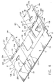
- FIGURE 4 shows three stacked containers 21, 24, 26, the interengagement of corresponding projections 31 and notches 35 keeps any practicable number of stacked containers in substantial registration with each other, and thus resists inadvertent horizontal displacement which might cause the containers to fall from pallet 22 either singularly or as a collapsing "tower.”
- projections 31 and notches 35 cause the side walls of the containers to bear on one another, substantially confining vertical compression forces to the side walls, which are reinforced and made quite strong by the superimposition of multiple layers of material, namely side panels 25a-25d.
- side panels 25a-d The structure of side panels 25a-d is seen with reference to FIGURES 1-3 and 5.
- Side panels 25b and 25c constitute inner panels in that they are inside each of the sides 23 and are adjacent to each other.
- outer panels 25a and 25d On either side of inner panels 25b and c are outer panels 25a and 25d.
- Outer panel 25a is adjacent to inner panel 25b, whereas outer panel 25d is adjacent to inner panel 25c.
- Projections 31 are located on at least one of the inner panels 25b or 25c on each of sides 23. In this embodiment, projections 31 are formed by portions of both inner panels 25b and 25c which are in registered relationship with each other, which extend co-extensively from sides 23, and which therefore give projections 31 a double-wall thickness (FIGURE 3).
- Notches 35 are also formed in at least one of the inner panels 25b and 25c at lower horizonal edges 38 of opposite sides 23.
- notches 35 are formed in both inner panels 25b and 25c by cut-away portions 43 which are in substantial registration with each other, which extend co-extensively into sides 23 from lower horizontal edges 38, and therefore provide each notch 35 with a double-wall thickness.
- Notches 35 are further defined by longitudinally extending sidewall portions 45 of outer panels 25a and 25d. Notches 35 are sized to receive projections 31 therein.
- projections 31 may assume a variety of shapes, one preferred shape is generally rectangular, advantageously with a slight taper.
- the tabs are elongated so as to extend a greater distance along horizontal edges 33 than they extend outwardly therefrom.
- the tabs and the notches are preferably closely complementary, although the tabs can be tapered while the notches are substantially rectangular, having a width equal to that of the base of the tabs.
- FIGURE 5 shows a blank 121 of corrugated sheet material from which container 21 is made.
- the blank can be die cut from a larger sheet, and due to the substantially rectangular and compact form of the die cut blank 121, waste of material is minimized.
- side panels 25b, 25c and 25d each have openings 37 therein. These openings are positioned so that, when container 21 is erected as shown in FIGURE 1, openings 37 are in substantial registration with each other to define handholds 29 in sides 23 of container 21 (FIGURE 1).
- Interior panels 25a on each of sides 23 have a solid portions 39 (FIGURE 1) in registration with openings 37 in exterior panels 25b-d. The solid portions 39 thereby prevent access through handholds 29 to contained space 27.
- Container 21 thus may be easily picked up or otherwise manipulated by inserting fingers into handholds 29 without fear of damaging contents held in contained space 27.
- the handholds confine forces on the container when carried to the side walls in the same manner that the multiple thickness interlocking side walls of containers in a standing stack form supporting columns. Two or more containers can be readily carried by the handholds with the sidewalls locking the containers together and bearing the load with substantial support from the sidewalls of the coupled containers.
- each of the panels 25a-25d each extend substantially between corresponding upper horizontal edge 33 and lower horizontal edge 38. In this way, each of the panels 25a-d acts to increase the compressive strength of sides 23.
- the side panels 25a-25d in this embodiment have opposing surfaces which are in substantial contact with each other, thereby forming a multi-layer, sandwich-like structure which is resistant to lateral deflection, in part because the opposing surfaces of panels 25a-25d bear against each other when exposed to a lateral deflecting force.
- container 21 has a front 47 with cutaways 49 defined therein.
- cutaways 49 facilitate access to product packages 51, especially if multiple product packages 51 are stacked within container 21 one on top of another. Under such circumstances, access to lower layers of the stacks of product packages 51 is facilitated because cutaways 49 allow access to portions of such packages through front 47 of container 21 rather than needing to access such layers through the top of container 21.
- bottom 41 of container 21 comprises multiple bottom flaps 53.
- Bottom flaps 53 are foldably connected to sides 23, front 47, and back 55 of container 21 in any suitable manner to span contained space 27 of container 21.
- Bottom flaps 53 may at least partially overly one another in a manner known in the art to provide suitable strength to bottom 41 of container 21.
- Bottom panels or flaps 53 have formed therein bottom cutouts or notches 57 shown in FIGURES 2b and 5.
- Bottom notches 57 are selectively placed along edges of certain ones of bottom flaps 53 so that, when the carton 21 is erected, bottom notches 57 are in substantial registration with corresponding notches 35 at the lower edges 38 of sides 23.
- bottom notches 57 define a portion of notches 35 and allow corresponding projections 31 to engage notches 35 from the bottom 41 of the container 21.
- Bottom flaps 53 of an overlying container thus do not interfere with interengagement of notches 35 with corresponding projections 31 of an underlying container (FIGURE 4).
- Partition 59 substantially, vertically spans the height of contained space 27 and thereby strengthens the compressive strength of container 21.
- Partition 59 preferably comprises a pair of partition panels 61, which are preferably foldably connected to each other and whose opposing surfaces are in substantial contact with each other for form a two layer partition 59.
- Container 21 is preferably formed from a single sheet of corrugated paperboard stock suitably die-cut and perforated to form multiple, foldably connected panels, such as shown in the blank 121 in FIGURE 5.
- Blank 121 is a sheet of material comprising a plurality of panels foldably attached to one another, and the panels have been identified with reference numerals corresponding to the elements of the erected container 21 shown in FIGURES 1-4.
- Side panels 25d are attached to front panel 47 at opposite edges 123 of front panel 47. Opposite edges 123 each comprise a pair of vertically extending fold lines 125 which are slightly, laterally spaced from each other to accommodate the multi-layer thickness of what will become sides 23 of container 21.
- Panels corresponding to back 55 of container 21 are foldably connected at each outer edge 127 of side panels 25d.
- Bottom flaps 53 are foldably connected to lower edges 131 of panels 47, 25d, and 55.
- Partition 59 comprises two partition panels 61, 62, which are foldably connected to one of the outer edges 129 of back 55.
- Partition panel 62 has opposite, transverse edges 66 and opposite longitudinal edges 64 extending therebetween.
- Panel 62 is connected to partition panel 61 along one of its longitudinal edges 64.
- a partition flap 68 is defined integrally with panel 62 at one of the transverse edges 64.
- the flap 68 is foldable along an axis indicated by 70 which is substantially parrallel to the transverse edges 64.
- Flap 68 has two tab sections 72 extending in relatively opposite directions from axis 70. When flap 68 is folded about axis 70, the tabs 72 extend outwardly from a plane coincident with panel 62.
- Flap 68 is defined by a pair of fold lines 74 coincident with axis 70, each extending inwardly from a corresponding one of the longitudinal edges 64 and terminating in a cut 76. Cut 76 extends inwardly from axis 70.
- the two-wall thickness of partition 59 is formed by folding panel 62 in the direction indicated by the arrow D so that it overlies panel 61. When thus folded, the partition panel 62 and its coplanar partition flap 68 comprise the upper of the two layers as shown in FIGURE 5.
- Side panels 25a-d are arranged adjacent each other in two "T" configurations which will form the two opposite sides 23 when container 21 is in the deployed state shown in FIGURE 1.
- Side panels 25d have upper transverse edges 133 to which side panels 25a are foldably attached.
- Side panels 25a in turn, have inner vertical edges 135 to which side panels 25c are foldably connected.
- Side panels 25a have outer vertical edges 137 opposite inner vertical edges 135.
- Side panels 25b are foldably connected to outer vertical edges 137.
- a corrugated sheet or blank 121 may be suitably folded and glued to form a blank 221, shown in FIGURE 6, using a fold-and-glue machine through which blanks are fed.
- Blank 221 also known as a shipper's blank, is in the collapsed form generally sent by the container manufacturer to its customers for their use in packing products for shipment to end-user locations.
- side panels 25b are folded along outer vertical edges 137 in the direction indicated by arrows A to overlie side panels 25a.
- side panels 25c are folded along inner vertical edges 135 in the direction indicated by arrows B to overly side panels 25b.
- Inner vertical edges 135 (FIGURE 5) comprise a pair of slightly, laterally spaced fold lines 139 to account for the thickness of side panel 25b.
- One or more of side panels 25a-25c are provide with a suitable pattern of adhesive to form three-layer, reinforcing panels 139 (FIGURE 6).
- the die-cut and perforated blank 121 (FIGURE 5) is folded generally in the direction indicated by the arrows C. Partition flap 68 is adhered to zone 141. Although the folding of side panels 25a-d and partition panels 61, 62 described above has created various multi-layer structures, partition flap 68 is readily adherable to zone 141 because partition panel 62 directly opposes front panel 47 without intermediate panel layers inhibiting good contact therebetween. When flap 68 is adhered in this manner, tabs 72 are secured and become positioned to either side of partition 59 when the container is erected as shown in FIGURE 1. At a suitable point during the folding of blank 121, outer edges 129 are generally adhered to each other to form back 55.
- FIGURE 6 The erection of blank 221 can be appreciated with reference to FIGURE 6, in which the blank 221 is shown with the front side 47 of container 21 facing upwardly. (Structures corresponding to those found in the blank 121 of sheet material have been given like reference numerals as they appear in blank 221.)
- side panels 25d are foldably attached to outer side edges 123 of front 47.
- Back 55 of container 21 remains foldably connected to outer edges 127, one of which is shown in FIGURE 6 (both of which are seen in FIGURE 5).
- Side panels 25d correspond to the exterior sidewalls of carton 21 when it is deployed.
- Reinforcing panels 139 are foldably connected to corresponding upper, transverse edges 133 of side panels 25d.
- Each of the reinforcing panels 139 comprises three layers: a base layer corresponding to side panel 25a and two, overlying layers corresponding to side panels 25b and 25c.
- one of the reinforcing panels 139 (on the left of FIGURE 6) is facing downward so as to reveal its base layer corresponding to side panel 25a, whereas the other reinforcing panel 139 is facing upward, thereby revealing the uppermost, overlying layer corresponding to side panel 25c.
- Overlying side panels 25b and c each have a pair of transverse edges 225 and 227, which are substantially parallel to each other and to corresponding transverse edges 133 of side panels 25d. Transverse edges 225 are laterally closer to transverse edges 133 than are transverse edges 227. A pair of transversely spaced notches 35 is formed in each of the transverse edges 227, and a pair of transversely spaced projections 31 extends from transverse edges 225.
- Notches 35 and projections 31 are located on transverse edges 227, 225, respectively, so that, when side panels 25b and 25c are folded over side panels 25a to form reinforcing panels 139, the notches 35 and projections 31 of adjacent, overlying panels 25b and c are in registration with each other and thereby form projections 31 and notches 35 of double-wall thickness.
- side panels 25b and 25c each have openings 37 defined therein so that, upon folding to form reinforcing panels 139, a handhold 29 of double wall thickness is preliminarily formed on reinforcing panel 139.
- transverse-edges 225 and 133 are substantially parallel to each other and laterally spaced from each other by a distance equal to the width of web portions 223.
- the edges of web portions 223 include fold lines 231 generally aligned with transverse edges 225 of overlying panels 25b and 25c.
- Web portions 223 each have a pair of apertures 229 defined therein, which are positioned in alignment with and proximate to projections 31.
- Apertures 229 extend between opposing transverse edges 225, 133 and have a length substantially equal to or slightly exceeding the length of the tabbed-shaped projections 31.
- Reinforcing panels 139 are folded generally inwardly along fold lines 231 in the direction of the nascent contained space 27 (FIGURE 1), such as indicated by the arrows D (FIGURE 6) until they are adjacent to, and in registration with, side panels 25d at respective opposite sides 23 of container 21.
- Bottom flaps 53 are suitably folded to create bottom 41 of container 21 (FIGURE 1).
- Web portion 223 has a width so that, when the carton is erected and reinforcing panels 139 are folded adjacent to side panels 25d, transverse edges 225 are in substantial alignment with transverse edges 133 and thereby form upper, horizontal edges 33 shown in FIGURE 1 with double wall thickness projections 31 extending beyond edges 33.
- Side panels 25b and c have their transverse edges 227 located so that transverse edges 227 abut bottom 41 of carton 21, thereby providing a reinforcing function to sides 23 of container 21.
- Openings 37 in reinforcing panels 139 are in registration with corresponding openings 37 in side panels 25d, so that, when the reinforcing panels 139 have been folded into place at sides 23 of container 21, the handholds 29 have a triple-wall thickness defined by the three openings 37 of panels 25b-25d in registration with each other. Since side panels 25a do not have openings 37 therein, portions of such side panels 25a span the handholds 29 to close off access to contained space 27 through handholds 29.
- notches 35 in reinforcing panels 139 become aligned with bottom notches 57 in bottom flaps 53 so that notches 35 of container 21 may be engaged through its bottom 41 by projections 31 extending from the top of a second, underlying container 24 (FIGURE 4).
- container 21 may be filled with product 51 and stacked with one or more other containers, such as containers 24 and 29 shown in FIGURE 4.
- Each of the containers 21, 24, and 29 has a similar "footprint" or configuration in plan, and each of the containers has projections 31 and notches 35 located so that, when the containers are stacked in registration with each other, projections and corresponding notches of adjacent containers on the stack interengage. It is also possible to place the projections and notches so that alternating layers of containers can lap over one with an upper container engaging one projection from each of two adjacent containers on the next lower level. This feature can be used in particular for making pyramid shaped stacks as opposed to tower stacks where the containers on each level are strictly in registry.
- a selected number of containers 21, 24, 29 filled with product 51 are stacked on pallet 22, and pallet 22 may be moved from receiving directly to the display floor of the retailer (perhaps after removing an external common cover, strapping or wrap), where end-user purchasers have access to the pallet of containers.
- the individual containers 21, 24, 29 do not include covers, tops or lids of corrugated material, instead being arranged such that the upper containers engage over and cover the next lower one.
- the containers are accessed on the display floor and generate less waste.
- Purchasers may select product 51 from one of the open containers, generally from those containers at the top of the stack.
- Handholds 39 allow containers to be easily manipulated by stock personnel or others, individually or in stacks of two or more. The containers' interengagement keeps the containers from being inadvertently horizontally knocked off the pallet or off of the stacks of containers.
- the present invention may be formed from cardboard or other corrugated material with any of a variety of thicknesses and strength characteristics. Paperboard is also suitable. A preferred stock is standard corrugated craft, in a weight chosen to reflect the weight of the contents intended for the container.
- partition 59 while it helps give compressive strength and lateral rigidity to container 21, is optional and may be dispensed with altogether in certain applications.
- additional reinforcing partitions similar to that of partition 59 may also be provided.
- each of sides 23 may include only three side panels, such as if one of the inner panels 25b or c were removed. In such alternative embodiment, there would be a total of eight vertical walls providing compressive strength to container 21.
- the container of the invention may also include a top or other means to cover the container.
- the number, location, and configuration of projections 31, notches 35 and handholds 39 may also be varied depending on particular applications and use conditions.
- the handholds 29 are preferably eliminated from the container. Such an arrangement leaves side panels 25a-d (as well as the resulting sides 23) without apertures therein which would otherwise diminish their resistance to compression.
- FIGURE 7 Another alternative embodiment is similar to the container 21 shown in FIGURE 1, except that the projections 31 and notches 35 have been eliminated, as well as the handholds 29.
- a blank 321 for such alternative container is shown in FIGURE 7.
- Blank 321 is similar to the blank 121 in die-cut sheet form shown in FIGURE 5, -except that openings 37 for handholds 29, and notches 39 and 57 have been eliminated. Otherwise, like reference numerals have been used to indicate similar structures.
- the present invention improves the container's strength, especially its resistance to being collapsed or crushed in the vertical direction.
- a related advantage is that the contents of such containers are less likely to be damaged.
- the present invention allows containers to remain in registration with each other and resist being moved out of such registration. In other words, when adjacent containers have corresponding projections 31 and notches 33 interengaged, it is less likely that such containers will be inadvertently, horizontally displaced or knocked off the stack of underlying containers.
- the containers according to the present invention are easy to move by means of handholds 29, and the containers of the invention minimize the amount of scrap that needs to be removed from the display floor when the containers are used directly off of pallets.
Claims (14)
- Conteneur comprenant plusieurs panneaux positionnés de manière à former un fond, une face avant et arrière et deux côtés, les côtés présentant un premier bord et un second bord s'étendant essentiellement à l'horizontale, les côtés comprenant au moins trois panneaux concordants latéraux (25a-d), au moins un des côtés présentant une saillie (31) s'étendant à partir du premier bord, et un élément (35) formant un logement pour la saillie, situé sur le second bord ;
une séparation (59) orientée verticalement et située dans le conteneur de manière à former au moins deux compartiments à l'intérieur de celui-ci ; la séparation (59) étant formée d'une paire de panneaux de séparation (61, 62) entiers pliés présentant deux bords transversaux opposés (66), un desdits panneaux étant plié le long d'un axe sur un desdits bords transversaux pour former une première et une seconde languettes (72) s'étendant sur les côtés opposés de l'axe dans des directions essentiellement opposées, la première et la seconde languettes (72) s'étendant généralement à l'extérieur des plans coïncidents avec les panneaux de séparation. - Conteneur selon la revendication 1, sachant que chacun des côtés comprend deux saillies (31) et deux éléments (35) formant un logement pour la saillie.
- Conteneur selon la revendication 1 ou 2, sachant que les côtés présentent au moins quatre panneaux latéraux (25a-d), comprenant deux panneaux intérieurs adjacents et deux panneaux extérieurs, le premier panneau extérieur étant adjacent à un des panneaux intérieurs et le second panneau extérieur adjacent à l'autre panneau intérieur, la saillie et l'élément formant un logement pour la saillie étant situés sur au moins un des panneaux intérieurs sur chacun des côtés.
- Conteneur selon l'une des revendications précédentes, sachant que la saillie (31) présente une double épaisseur formée par une partie des deux panneaux intérieurs concordants qui s'étendent à partir des côtés, et sachant que l'élément (35) formant un logement pour la saillie comprend une encoche ayant une double épaisseur définie par les bords des deux panneaux intérieurs concordants.
- Conteneur selon la revendication 4, sachant que l'encoche est de plus définie par les parois latérales (43, 45) s'étendant longitudinalement, les parois latérales comprenant des parties des panneaux extérieurs.
- Conteneur selon la revendication 4 ou 5, sachant que chacun des côtés comprend une paire de saillies (31) et une paire de encoches (35).
- Conteneur selon la revendication 6, sachant que la paire de saillies (31) sont situées sur le premier bord et la paire de encoches (35) sur le second bord.
- Conteneur selon l'une des revendications précédentes, pour l'empilage sur un deuxième conteneur et sachant qu'au moins une des saillies (31) ou un des éléments (35) formant un logement pour la saillie s'enclenche dans le deuxième conteneur lorsque les conteneurs sont empilés.
- Conteneur selon l'une des revendications précédentes, pour l'empilage sur un deuxième conteneur ayant des parois latérales s'opposant, et sachant qu'au moins une des saillies (31) ou un des éléments (35) formant un logement s'enclenche au moins dans une des parois latérales du deuxième conteneur lorsque les conteneurs sont empilés de façon superposée.
- Conteneur selon une des revendications précédentes, sachant que chacun des panneaux s'étend essentiellement entre les bords latéraux pour renforcer la résistance à la compression des côtés.
- Conteneur selon l'une des revendications 3 à 10, sachant que le fond, l'avant, l'arrière et les côtés définissent un espace contenu, et que les quatre panneaux comprennent un panneau intérieur adjacent à l'espace contenu et trois panneaux extérieurs par rapport au panneau intérieur, les panneaux extérieurs présentant parties de ouvertures définies, les ouvertures étant concordants les unes aux autres pour former poignées (39) sur les côtés du conteneur, le panneau intérieur présentant une partie concordante à l'ouverture pour empêcher l'accès, par les poignées, à l'espace contenu.
- Conteneur selon l'une des revendications précédentes, sachant que le fond, l'avant, l'arrière et les côtés sont formés en pliant une pièce brute de carton ondulé dans lequel les panneaux sont entièrement formés.
- Conteneur selon l'une des revendications précédentes, sachant que les surfaces des panneaux latéraux quise font face sont pour l'essentiel en contact entre elles.
- Conteneur selon l'une des revendications précédentes, sachant que la saillie consiste en une languette allongée.
Applications Claiming Priority (3)
| Application Number | Priority Date | Filing Date | Title |
|---|---|---|---|
| US814731 | 1997-03-07 | ||
| US08/814,731 US5839650A (en) | 1997-03-07 | 1997-03-07 | Stackable container |
| PCT/US1998/004532 WO1998039224A1 (fr) | 1997-03-07 | 1998-03-09 | Conteneur empilable |
Publications (3)
| Publication Number | Publication Date |
|---|---|
| EP1015334A1 EP1015334A1 (fr) | 2000-07-05 |
| EP1015334A4 EP1015334A4 (fr) | 2004-04-28 |
| EP1015334B1 true EP1015334B1 (fr) | 2005-11-09 |
Family
ID=25215851
Family Applications (1)
| Application Number | Title | Priority Date | Filing Date |
|---|---|---|---|
| EP98909044A Expired - Lifetime EP1015334B1 (fr) | 1997-03-07 | 1998-03-09 | Conteneur empilable |
Country Status (12)
| Country | Link |
|---|---|
| US (1) | US5839650A (fr) |
| EP (1) | EP1015334B1 (fr) |
| AR (1) | AR011951A1 (fr) |
| AT (1) | ATE309141T1 (fr) |
| AU (1) | AU6692698A (fr) |
| BR (1) | BR9808217A (fr) |
| CA (1) | CA2283877C (fr) |
| DE (1) | DE69832292D1 (fr) |
| IL (1) | IL131774A0 (fr) |
| NZ (1) | NZ337671A (fr) |
| PE (1) | PE32299A1 (fr) |
| WO (1) | WO1998039224A1 (fr) |
Families Citing this family (40)
| Publication number | Priority date | Publication date | Assignee | Title |
|---|---|---|---|---|
| US6056133A (en) * | 1995-06-09 | 2000-05-02 | Luenser; Carl D. | Display device and storage rack component having a hanging member and a resting member integrally formed with and removable from the component |
| US6158653A (en) * | 1999-02-10 | 2000-12-12 | Allen Kanter | Container having improved stacking strength |
| US6817514B2 (en) * | 1999-02-10 | 2004-11-16 | Innovation Packaging Designs L.P. | Container having corner support |
| US6098873A (en) * | 1999-02-19 | 2000-08-08 | Pack `N` Stack, Inc. | One piece folded and glued container with tabbed columns |
| CA2370327C (fr) | 1999-05-07 | 2006-12-19 | Pack 'n' Stack, Inc. | Recipient d'empilage colle et plie a acces lateral |
| US6179156B1 (en) | 2000-02-04 | 2001-01-30 | Rehrig Pacific Company | Multi-purpose container |
| US6568588B2 (en) | 2001-06-15 | 2003-05-27 | James K. Holdsworth | Stackable display container |
| US7118023B2 (en) * | 2002-06-14 | 2006-10-10 | Holdsworth James K | Stackable display container |
| US7004379B2 (en) * | 2002-06-14 | 2006-02-28 | Holdsworth James K | Stackable display container |
| US7337909B1 (en) * | 2003-07-03 | 2008-03-04 | Structural Graphics, Llc | Advertising/promotional display and/or storage system |
| US20050121348A1 (en) * | 2003-12-09 | 2005-06-09 | Clare Timothy P. | Package insert and stackable package for articles |
| US20050161495A1 (en) * | 2004-01-22 | 2005-07-28 | Shepherd Russell A. | Stackable display container, its preassembly and blank for making same |
| US20060038000A1 (en) * | 2004-08-20 | 2006-02-23 | Sheffer Phil B | Stacking display containers |
| US20060060643A1 (en) * | 2004-08-20 | 2006-03-23 | Sheffer Phil B | Display containers with removable panel |
| US20060138204A1 (en) * | 2004-12-28 | 2006-06-29 | Keefe Walter D Jr | Stackable container with angled corner panel and container blank |
| US20060138205A1 (en) * | 2004-12-28 | 2006-06-29 | Keefe Walter D Jr | Stackable container with air cell corner assembly and associated container blank |
| US20060138206A1 (en) * | 2004-12-28 | 2006-06-29 | Keefe Walter D Jr | Stackable container and container blank (L corner) |
| US7520390B2 (en) | 2005-03-24 | 2009-04-21 | The Kroger Co. | Configurable display container |
| US20060213150A1 (en) * | 2005-03-24 | 2006-09-28 | Sonon James A | Method for product handling using a configurable display container |
| US7588404B2 (en) | 2005-03-24 | 2009-09-15 | The Kroger Co. | Container handling apparatus and container |
| WO2009140346A1 (fr) * | 2008-05-14 | 2009-11-19 | Cadbury Adams Usa Llc | Emballage et plateau formés de flancs imbriqués |
| FR2942424A1 (fr) * | 2009-02-23 | 2010-08-27 | Serge Laskar | Systeme de rangement modulaire juxtaposable et superposable. |
| US20100320109A1 (en) * | 2009-06-22 | 2010-12-23 | Anthony Trumbauer | Method Of Shipping and Displaying Products For Sale To Consumers And Associated Product Display |
| US10196170B2 (en) | 2010-09-03 | 2019-02-05 | Georgia-Pacific Corrugated Llc | Reinforced packing container |
| CA2810052C (fr) | 2010-09-03 | 2019-05-14 | Georgia-Pacific Corrugated Llc | Contenant d'emballage |
| FR2976919B1 (fr) * | 2011-06-27 | 2015-08-14 | Tecma Pack | Emballage d'objets disposes en une ou plusieurs couches. |
| US8864014B2 (en) | 2011-10-05 | 2014-10-21 | International Paper Co. | Display tray with adjustable compartments |
| MX353090B (es) | 2012-02-03 | 2017-12-19 | Rock Tenn Shared Services Llc | Contenedores poligonales reforzados y plantillas para fabricarlos. |
| US9205947B1 (en) | 2012-05-30 | 2015-12-08 | Green Bay Packaging, Inc. | Multi-component container with air cell end panel reinforcements |
| USD721495S1 (en) * | 2012-09-07 | 2015-01-27 | William Mitchell Scott | Box |
| USD720539S1 (en) * | 2012-09-07 | 2015-01-06 | William Mitchell Scott | Box |
| US9352888B2 (en) | 2012-09-07 | 2016-05-31 | William Mitchell Scott | Shipping container with grips and locking ports |
| PL2943411T3 (pl) | 2013-01-09 | 2019-03-29 | Georgia-Pacific Corrugated Llc | Wzmocniony karton |
| US10611513B2 (en) | 2014-01-29 | 2020-04-07 | General Mills, Inc. | Paperboard carton |
| US10315798B2 (en) | 2015-06-22 | 2019-06-11 | Menasha Corporation | Stackable pallet display |
| CA2991758C (fr) | 2015-07-24 | 2020-09-08 | General Mills, Inc. | Boite en carton |
| WO2017142528A1 (fr) | 2016-02-17 | 2017-08-24 | General Mills, Inc. | Boîte en carton |
| US10364064B2 (en) | 2017-02-22 | 2019-07-30 | Menasha Corporation | Pallet with skirt |
| US10772442B2 (en) | 2017-10-25 | 2020-09-15 | Menasha Corporation | Snack pallet assembly |
| CA3104378C (fr) | 2018-07-06 | 2023-07-11 | Intercontinental Great Brands Llc | Plateau et son procede d'assemblage |
Family Cites Families (18)
| Publication number | Priority date | Publication date | Assignee | Title |
|---|---|---|---|---|
| US2893621A (en) * | 1955-05-25 | 1959-07-07 | Crown Zellerbach Corp | Nestable berry tray |
| US2914235A (en) * | 1956-05-31 | 1959-11-24 | Container Corp | Foldable interlocked boxes |
| US3102674A (en) * | 1962-01-18 | 1963-09-03 | American Box Corp Of Californi | Strawberry tray |
| US3157346A (en) * | 1962-06-26 | 1964-11-17 | American Box Corp Of Californi | Stacking paperboard lug box |
| US3734392A (en) * | 1971-06-03 | 1973-05-22 | Container Corp | Multi-wall container |
| US3756499A (en) * | 1972-03-09 | 1973-09-04 | Union Camp Corp | Box with five panel ends |
| US3940053A (en) * | 1974-08-01 | 1976-02-24 | Weyerhaeuser Company | Single-piece container blank with multi-ply end panels |
| US3929273A (en) * | 1974-09-12 | 1975-12-30 | Hoerner Waldorf Corp | Tray for strawberries and the like |
| US4101048A (en) * | 1976-06-01 | 1978-07-18 | International Paper Company | Produce field box and foldable blank for making it |
| US4058249A (en) * | 1976-10-07 | 1977-11-15 | Domtar Limited | Stacking tray |
| US4165031A (en) * | 1978-03-22 | 1979-08-21 | Westvaco Corporation | Short depth returnable bottle container |
| US4347969A (en) * | 1981-05-08 | 1982-09-07 | Weyerhaeuser Company | Tray |
| US4356952A (en) * | 1981-06-08 | 1982-11-02 | Champion International Corporation | Stackable tray with corner supports |
| DE8614293U1 (de) * | 1986-05-27 | 1986-07-17 | Fulda Verpackung Stabernack jr. GmbH, 36043 Fulda | Zuschnitt aus Faltmaterial für eine quaderförmige Faltschachtel, insbesondere für Weinflaschen |
| US4770339A (en) * | 1987-05-06 | 1988-09-13 | International Paper Company | Ventilated, stackable grape box |
| US5413276A (en) * | 1994-09-14 | 1995-05-09 | Triangle Container Corporation | Plural-component one-piece shipping and retail display carton |
| US5458283A (en) * | 1995-04-24 | 1995-10-17 | Packaging Corporation Of America | Stackable container for storing fresh produce |
| US5524815A (en) * | 1995-09-14 | 1996-06-11 | Triangle Container Corporation | Plural-compartment display carton with locking bottom and center support |
-
1997
- 1997-03-07 US US08/814,731 patent/US5839650A/en not_active Expired - Lifetime
-
1998
- 1998-03-09 EP EP98909044A patent/EP1015334B1/fr not_active Expired - Lifetime
- 1998-03-09 NZ NZ337671A patent/NZ337671A/en unknown
- 1998-03-09 IL IL13177498A patent/IL131774A0/xx not_active IP Right Cessation
- 1998-03-09 WO PCT/US1998/004532 patent/WO1998039224A1/fr active IP Right Grant
- 1998-03-09 CA CA002283877A patent/CA2283877C/fr not_active Expired - Lifetime
- 1998-03-09 AT AT98909044T patent/ATE309141T1/de not_active IP Right Cessation
- 1998-03-09 DE DE69832292T patent/DE69832292D1/de not_active Expired - Lifetime
- 1998-03-09 BR BR9808217-5A patent/BR9808217A/pt unknown
- 1998-03-09 AU AU66926/98A patent/AU6692698A/en not_active Abandoned
- 1998-03-10 AR ARP980101053A patent/AR011951A1/es unknown
- 1998-03-20 PE PE1998000200A patent/PE32299A1/es not_active Application Discontinuation
Also Published As
| Publication number | Publication date |
|---|---|
| ATE309141T1 (de) | 2005-11-15 |
| NZ337671A (en) | 2001-06-29 |
| EP1015334A1 (fr) | 2000-07-05 |
| AR011951A1 (es) | 2000-09-13 |
| EP1015334A4 (fr) | 2004-04-28 |
| CA2283877C (fr) | 2003-12-30 |
| IL131774A0 (en) | 2001-03-19 |
| WO1998039224A1 (fr) | 1998-09-11 |
| US5839650A (en) | 1998-11-24 |
| DE69832292D1 (de) | 2005-12-15 |
| AU6692698A (en) | 1998-09-22 |
| CA2283877A1 (fr) | 1998-09-11 |
| PE32299A1 (es) | 1999-03-25 |
| BR9808217A (pt) | 2000-05-16 |
Similar Documents
| Publication | Publication Date | Title |
|---|---|---|
| EP1015334B1 (fr) | Conteneur empilable | |
| US5520325A (en) | Channel H divider pack | |
| AU757279B2 (en) | Stackable container | |
| US7467743B1 (en) | Container having self-locking structure to provide added stability | |
| US6502698B1 (en) | One touch tray for produce and the like | |
| US7118023B2 (en) | Stackable display container | |
| US20060249565A1 (en) | Display carton and method for displaying product using same | |
| US6568588B2 (en) | Stackable display container | |
| US7004379B2 (en) | Stackable display container | |
| US5447269A (en) | Multiple unit box and blank therefor | |
| CA2138467A1 (fr) | Enveloppe de protection pour emballage | |
| US9409671B2 (en) | Basket assembly | |
| US20030052038A1 (en) | Corrugated container with integral pallet | |
| US10364064B2 (en) | Pallet with skirt | |
| US20060138206A1 (en) | Stackable container and container blank (L corner) | |
| US9205947B1 (en) | Multi-component container with air cell end panel reinforcements | |
| AU4183099A (en) | Fold and glue stacking container with side access | |
| US20060138204A1 (en) | Stackable container with angled corner panel and container blank | |
| US20060038000A1 (en) | Stacking display containers | |
| US20060144910A1 (en) | Container and container blank usable with a liquid impermeable bag | |
| US20060138205A1 (en) | Stackable container with air cell corner assembly and associated container blank | |
| US20090159488A1 (en) | Container having top and bottom reinforcement | |
| MXPA04006200A (es) | Preforma de bandeja convertible y contenedor. | |
| US6305598B1 (en) | Stackable package capable of division | |
| AU2020256374A1 (en) | Shipping and display container and blank for forming same |
Legal Events
| Date | Code | Title | Description |
|---|---|---|---|
| PUAI | Public reference made under article 153(3) epc to a published international application that has entered the european phase |
Free format text: ORIGINAL CODE: 0009012 |
|
| 17P | Request for examination filed |
Effective date: 19991006 |
|
| AK | Designated contracting states |
Kind code of ref document: A1 Designated state(s): AT BE CH DE DK ES FI FR GB GR IE IT LI LU MC NL PT SE |
|
| A4 | Supplementary search report drawn up and despatched |
Effective date: 20040315 |
|
| RIC1 | Information provided on ipc code assigned before grant |
Ipc: 7B 65D 5/02 B Ipc: 7B 65D 5/46 B Ipc: 7B 65D 5/48 B Ipc: 7B 65D 5/00 B Ipc: 7B 65D 25/04 A |
|
| 17Q | First examination report despatched |
Effective date: 20040915 |
|
| GRAP | Despatch of communication of intention to grant a patent |
Free format text: ORIGINAL CODE: EPIDOSNIGR1 |
|
| GRAS | Grant fee paid |
Free format text: ORIGINAL CODE: EPIDOSNIGR3 |
|
| GRAA | (expected) grant |
Free format text: ORIGINAL CODE: 0009210 |
|
| AK | Designated contracting states |
Kind code of ref document: B1 Designated state(s): AT BE CH DE DK ES FI FR GB GR IE IT LI LU MC NL PT SE |
|
| PG25 | Lapsed in a contracting state [announced via postgrant information from national office to epo] |
Ref country code: NL Free format text: LAPSE BECAUSE OF FAILURE TO SUBMIT A TRANSLATION OF THE DESCRIPTION OR TO PAY THE FEE WITHIN THE PRESCRIBED TIME-LIMIT Effective date: 20051109 Ref country code: LI Free format text: LAPSE BECAUSE OF FAILURE TO SUBMIT A TRANSLATION OF THE DESCRIPTION OR TO PAY THE FEE WITHIN THE PRESCRIBED TIME-LIMIT Effective date: 20051109 Ref country code: IT Free format text: LAPSE BECAUSE OF FAILURE TO SUBMIT A TRANSLATION OF THE DESCRIPTION OR TO PAY THE FEE WITHIN THE PRESCRIBED TIME-LIMIT;WARNING: LAPSES OF ITALIAN PATENTS WITH EFFECTIVE DATE BEFORE 2007 MAY HAVE OCCURRED AT ANY TIME BEFORE 2007. THE CORRECT EFFECTIVE DATE MAY BE DIFFERENT FROM THE ONE RECORDED. Effective date: 20051109 Ref country code: FI Free format text: LAPSE BECAUSE OF FAILURE TO SUBMIT A TRANSLATION OF THE DESCRIPTION OR TO PAY THE FEE WITHIN THE PRESCRIBED TIME-LIMIT Effective date: 20051109 Ref country code: CH Free format text: LAPSE BECAUSE OF FAILURE TO SUBMIT A TRANSLATION OF THE DESCRIPTION OR TO PAY THE FEE WITHIN THE PRESCRIBED TIME-LIMIT Effective date: 20051109 Ref country code: BE Free format text: LAPSE BECAUSE OF FAILURE TO SUBMIT A TRANSLATION OF THE DESCRIPTION OR TO PAY THE FEE WITHIN THE PRESCRIBED TIME-LIMIT Effective date: 20051109 Ref country code: AT Free format text: LAPSE BECAUSE OF FAILURE TO SUBMIT A TRANSLATION OF THE DESCRIPTION OR TO PAY THE FEE WITHIN THE PRESCRIBED TIME-LIMIT Effective date: 20051109 |
|
| REG | Reference to a national code |
Ref country code: GB Ref legal event code: FG4D |
|
| REG | Reference to a national code |
Ref country code: CH Ref legal event code: EP |
|
| REG | Reference to a national code |
Ref country code: IE Ref legal event code: FG4D |
|
| REF | Corresponds to: |
Ref document number: 69832292 Country of ref document: DE Date of ref document: 20051215 Kind code of ref document: P |
|
| PG25 | Lapsed in a contracting state [announced via postgrant information from national office to epo] |
Ref country code: SE Free format text: LAPSE BECAUSE OF FAILURE TO SUBMIT A TRANSLATION OF THE DESCRIPTION OR TO PAY THE FEE WITHIN THE PRESCRIBED TIME-LIMIT Effective date: 20060209 Ref country code: GR Free format text: LAPSE BECAUSE OF FAILURE TO SUBMIT A TRANSLATION OF THE DESCRIPTION OR TO PAY THE FEE WITHIN THE PRESCRIBED TIME-LIMIT Effective date: 20060209 Ref country code: DK Free format text: LAPSE BECAUSE OF FAILURE TO SUBMIT A TRANSLATION OF THE DESCRIPTION OR TO PAY THE FEE WITHIN THE PRESCRIBED TIME-LIMIT Effective date: 20060209 |
|
| PG25 | Lapsed in a contracting state [announced via postgrant information from national office to epo] |
Ref country code: DE Free format text: LAPSE BECAUSE OF FAILURE TO SUBMIT A TRANSLATION OF THE DESCRIPTION OR TO PAY THE FEE WITHIN THE PRESCRIBED TIME-LIMIT Effective date: 20060210 |
|
| PG25 | Lapsed in a contracting state [announced via postgrant information from national office to epo] |
Ref country code: ES Free format text: LAPSE BECAUSE OF FAILURE TO SUBMIT A TRANSLATION OF THE DESCRIPTION OR TO PAY THE FEE WITHIN THE PRESCRIBED TIME-LIMIT Effective date: 20060220 |
|
| PG25 | Lapsed in a contracting state [announced via postgrant information from national office to epo] |
Ref country code: MC Free format text: LAPSE BECAUSE OF NON-PAYMENT OF DUE FEES Effective date: 20060331 Ref country code: LU Free format text: LAPSE BECAUSE OF NON-PAYMENT OF DUE FEES Effective date: 20060331 |
|
| PG25 | Lapsed in a contracting state [announced via postgrant information from national office to epo] |
Ref country code: PT Free format text: LAPSE BECAUSE OF FAILURE TO SUBMIT A TRANSLATION OF THE DESCRIPTION OR TO PAY THE FEE WITHIN THE PRESCRIBED TIME-LIMIT Effective date: 20060410 |
|
| NLV1 | Nl: lapsed or annulled due to failure to fulfill the requirements of art. 29p and 29m of the patents act | ||
| REG | Reference to a national code |
Ref country code: CH Ref legal event code: PL |
|
| PLBE | No opposition filed within time limit |
Free format text: ORIGINAL CODE: 0009261 |
|
| STAA | Information on the status of an ep patent application or granted ep patent |
Free format text: STATUS: NO OPPOSITION FILED WITHIN TIME LIMIT |
|
| 26N | No opposition filed |
Effective date: 20060810 |
|
| PG25 | Lapsed in a contracting state [announced via postgrant information from national office to epo] |
Ref country code: FR Free format text: LAPSE BECAUSE OF FAILURE TO SUBMIT A TRANSLATION OF THE DESCRIPTION OR TO PAY THE FEE WITHIN THE PRESCRIBED TIME-LIMIT Effective date: 20061020 |
|
| EN | Fr: translation not filed | ||
| PGFP | Annual fee paid to national office [announced via postgrant information from national office to epo] |
Ref country code: IE Payment date: 20070419 Year of fee payment: 10 |
|
| PGFP | Annual fee paid to national office [announced via postgrant information from national office to epo] |
Ref country code: GB Payment date: 20070425 Year of fee payment: 10 |
|
| GBPC | Gb: european patent ceased through non-payment of renewal fee |
Effective date: 20080309 |
|
| PG25 | Lapsed in a contracting state [announced via postgrant information from national office to epo] |
Ref country code: FR Free format text: LAPSE BECAUSE OF FAILURE TO SUBMIT A TRANSLATION OF THE DESCRIPTION OR TO PAY THE FEE WITHIN THE PRESCRIBED TIME-LIMIT Effective date: 20051109 |
|
| REG | Reference to a national code |
Ref country code: IE Ref legal event code: MM4A |
|
| PG25 | Lapsed in a contracting state [announced via postgrant information from national office to epo] |
Ref country code: IE Free format text: LAPSE BECAUSE OF NON-PAYMENT OF DUE FEES Effective date: 20080310 |
|
| PG25 | Lapsed in a contracting state [announced via postgrant information from national office to epo] |
Ref country code: GB Free format text: LAPSE BECAUSE OF NON-PAYMENT OF DUE FEES Effective date: 20080309 |