US3756499A - Box with five panel ends - Google Patents
Box with five panel ends Download PDFInfo
- Publication number
- US3756499A US3756499A US00233260A US3756499DA US3756499A US 3756499 A US3756499 A US 3756499A US 00233260 A US00233260 A US 00233260A US 3756499D A US3756499D A US 3756499DA US 3756499 A US3756499 A US 3756499A
- Authority
- US
- United States
- Prior art keywords
- panels
- panel
- hinged
- partial
- box
- Prior art date
- Legal status (The legal status is an assumption and is not a legal conclusion. Google has not performed a legal analysis and makes no representation as to the accuracy of the status listed.)
- Expired - Lifetime
Links
Images


Classifications
-
- B—PERFORMING OPERATIONS; TRANSPORTING
- B65—CONVEYING; PACKING; STORING; HANDLING THIN OR FILAMENTARY MATERIAL
- B65D—CONTAINERS FOR STORAGE OR TRANSPORT OF ARTICLES OR MATERIALS, e.g. BAGS, BARRELS, BOTTLES, BOXES, CANS, CARTONS, CRATES, DRUMS, JARS, TANKS, HOPPERS, FORWARDING CONTAINERS; ACCESSORIES, CLOSURES, OR FITTINGS THEREFOR; PACKAGING ELEMENTS; PACKAGES
- B65D5/00—Rigid or semi-rigid containers of polygonal cross-section, e.g. boxes, cartons or trays, formed by folding or erecting one or more blanks made of paper
- B65D5/42—Details of containers or of foldable or erectable container blanks
- B65D5/4295—Ventilating arrangements, e.g. openings, space elements
-
- B—PERFORMING OPERATIONS; TRANSPORTING
- B65—CONVEYING; PACKING; STORING; HANDLING THIN OR FILAMENTARY MATERIAL
- B65D—CONTAINERS FOR STORAGE OR TRANSPORT OF ARTICLES OR MATERIALS, e.g. BAGS, BARRELS, BOTTLES, BOXES, CANS, CARTONS, CRATES, DRUMS, JARS, TANKS, HOPPERS, FORWARDING CONTAINERS; ACCESSORIES, CLOSURES, OR FITTINGS THEREFOR; PACKAGING ELEMENTS; PACKAGES
- B65D5/00—Rigid or semi-rigid containers of polygonal cross-section, e.g. boxes, cartons or trays, formed by folding or erecting one or more blanks made of paper
- B65D5/20—Rigid or semi-rigid containers of polygonal cross-section, e.g. boxes, cartons or trays, formed by folding or erecting one or more blanks made of paper by folding-up portions connected to a central panel from all sides to form a container body, e.g. of tray-like form
- B65D5/22—Rigid or semi-rigid containers of polygonal cross-section, e.g. boxes, cartons or trays, formed by folding or erecting one or more blanks made of paper by folding-up portions connected to a central panel from all sides to form a container body, e.g. of tray-like form held erect by extensions of one or more sides being doubled-over to enclose extensions of adjacent sides
-
- Y—GENERAL TAGGING OF NEW TECHNOLOGICAL DEVELOPMENTS; GENERAL TAGGING OF CROSS-SECTIONAL TECHNOLOGIES SPANNING OVER SEVERAL SECTIONS OF THE IPC; TECHNICAL SUBJECTS COVERED BY FORMER USPC CROSS-REFERENCE ART COLLECTIONS [XRACs] AND DIGESTS
- Y10—TECHNICAL SUBJECTS COVERED BY FORMER USPC
- Y10S—TECHNICAL SUBJECTS COVERED BY FORMER USPC CROSS-REFERENCE ART COLLECTIONS [XRACs] AND DIGESTS
- Y10S229/00—Envelopes, wrappers, and paperboard boxes
- Y10S229/915—Stacking feature
- Y10S229/919—Reinforced wall
-
- Y—GENERAL TAGGING OF NEW TECHNOLOGICAL DEVELOPMENTS; GENERAL TAGGING OF CROSS-SECTIONAL TECHNOLOGIES SPANNING OVER SEVERAL SECTIONS OF THE IPC; TECHNICAL SUBJECTS COVERED BY FORMER USPC CROSS-REFERENCE ART COLLECTIONS [XRACs] AND DIGESTS
- Y10—TECHNICAL SUBJECTS COVERED BY FORMER USPC
- Y10S—TECHNICAL SUBJECTS COVERED BY FORMER USPC CROSS-REFERENCE ART COLLECTIONS [XRACs] AND DIGESTS
- Y10S229/00—Envelopes, wrappers, and paperboard boxes
- Y10S229/93—Fold detail
- Y10S229/931—Fold includes slit or aperture
Definitions
- FIG. 1 is a plan view of a blank showing the score lines, cuts and slots which define the various parts of the box of the present invention
- FIG. 2 is a top view of the wire rim for reinforcing the top edge of the box
- FIGS. 3, 4 and 5 are perspective views of the blank of FIG. 1 in the various stages of setting up the blank into a box;
- FIG. 6 is a perspective view of the blank of FIG. 1 completely set up ready for use
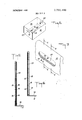
- FIG. 7 is a perspective partial view of the end of the box of FIG. 6 showing the five panels at the end of the box;
- FIG. 8 is a cross-sectional view along the line 8-8 of FIG. 7;
- FIG. 9 is a cross-sectional view along the line 9-9 of FIG. 7.
- the bottom panels 11 and 14 may be provided with ventilation holes 26 which are positioned to match when the blank is folded into a box and the inner bottom half panels 14 overlie the outer bottom panel 11.
- the various end panels l5, l6, l8 and 19 may be provided with handholes 27 or half handholes 27a which are positioned to match when the blank is folded into a box and the said panels are superimposed, thus constituting a single handhole at each end of the setup box.
- the inner bottom half panels 14 may also be provided with a thumb hole 28 which will permit gripping the panels for knocking the box down, if necessary for shipment in flat form.
- the corners of the various panels may be provided with circular cutouts 29 which will appear as cutouts in the bottom and top corners of the setup box. This permits insertion of a metal reinforcing member 30 (FIG. 2) in the upper rim of the box when the panels are folded in place. It also facilitates the folding and setting up of the box. Extending outwardly from the ends of the score line 23 are slots 31 which separate the panels 13 and 18. Likewise the slots 32 at the ends of the score lines 20 separate the panels 15 and 19.
- FIGS. 3 through 6 illustrate how the blank can be set up into a box without the necessity of any stitching, tape or tools.
- the panels 12 hinged to the outer bottom panel 11 are erected to a generally upright position.
- the intermediate end panels 18 are folded to lie flat against the intermediate end half panels 19 with the panel 18 on one side being folded inwardly and the opposite panel 18 on the other side being folded outwardly (FIG. 3).
- the four panels 18 and 19 are then superimposed so that the end of one panel 18 butts the end of the other panel 18 at approximately the center of the end.
- Panels 15 are raised to an upright position bottom half panels 14 flush against the bottom panel I l 'with the long edges of the panels 14 butting against each other along the middle of the bottom (FIG. 6). It will be seen that the various handhole cutouts match to provide a handhole at each end of the box.
- FIGS. 7, 8 and 9 illustrate the positions of the various panels in the ,ends of the setup box.
- the metal reinforcing member 30 When the metal reinforcing member 30 is to be included in the box to strengthen the rim of the box, such member is inserted before the inner panels are folded over the ends and sides.
- a four sided box formed from a generally rectangular blank of sheet material cut, scored and folded into said box having a bottom, two opposite side walls and two opposite end walls; each end wall comprising an outer end panel hinged to the bottom, an inner end panel hinged to the top of the outer end panel, a first intermediate end partial panel hinged to a side edge of one of the side walls, a first intermediate full panel hinged to the top of the first intermediate end partial panel and folded outwardly to lie flat against the outer face of the said first partial panel, a second intermediate end partial panel hinged to the opposite side edge of the other of the side walls, and a second intermediate full panel hinged to the top of the second intermediate end partial panel and folded inwardly to lie flat against the inner face of the said second partial panel, the sum of the widths of the said partial panels not exceeding the width of the end wall, said intermediate panels being positioned between the inner and outer end panels, the said panels of each end wall being cut out to provide a handhole for carrying the box; each side wall
Abstract
A four-sided box having ends with five panels to provide added strength, which box is formed from a one piece blank of generally rectangular shape.
Description
United States Patent 1191 Giebel et a]. Sept. 4, 1973 [54] BOX WITH FIVE PANEL ENDS 2,858,058 10/1958 Kitchell 229/34 R X 3,001,685 9/1961 [75] Inventors. Buddy E. Glebel, William H. Nation, 2,196,502 M940 both of Monroe, M1ch. 2,893,621 7/1959 2,957,615 10/1960 Karr et a1 229/34 R X [73] Asslgnee' 3''? Camp Wayne 3,157,346 ll/1964 Hamilton 229/34 R x 3,381,879 5/1968 Belcher et a1 229/34 R [22] Filed: Mar. 9, 1972 [211 App] 2 3 2 Primary Examiner-Davis T. Moorhead Attorney-Charles P. Bauer [52] U.S. Cl 229/34 R [51] Int. Cl 865d 5/22 [57] ABSTRACT 58 F 1d is h 229 34 1 m 0 can A four-sided box having ends with five panels to pro- [56] References Cited vide added strength, which box is formed from a one piece blank of generally rectangular shape.
5 Claims, 9 Drawing Figures PATENTEDSEP 41m 3.75 .499 SHEEI 3 UP 3 v BOX WITH FIVE PANEL ENDS BACKGROUND OF THE INVENTION SUMMARY OF THE INVENTION It is an object of the invention to provide a box with five panel ends for added strength.
It is a further object to provide a box with five panel ends which can be formed of a one-piece blank of generally rectangular shape.
It is a further object to provide a blank which is simple and economical to manufacture, can easily be set up into a box with five panel ends, which is efficient and well suited for its intended purpose.
BRIEF DESCRIPTION OF THE DRAWINGS Other objects and advantages will become apparent from the following description which is to be taken in conjunction with the accompanying drawings, in which:
FIG. 1 is a plan view of a blank showing the score lines, cuts and slots which define the various parts of the box of the present invention;
FIG. 2 is a top view of the wire rim for reinforcing the top edge of the box;
FIGS. 3, 4 and 5 are perspective views of the blank of FIG. 1 in the various stages of setting up the blank into a box;
FIG. 6 is a perspective view of the blank of FIG. 1 completely set up ready for use;
FIG. 7 is a perspective partial view of the end of the box of FIG. 6 showing the five panels at the end of the box;
FIG. 8 is a cross-sectional view along the line 8-8 of FIG. 7; and
FIG. 9 is a cross-sectional view along the line 9-9 of FIG. 7.
DESCRIPTION OF THE PREFERRED EMBODIMENT els 15, inner end panels 16, intermediate side partial panels 17, intermediate end panels 18, and intermediate end half panels 19. The outer bottom panel 11, the outer side panels 12, the inner side panels 13 and the inner bottom half panels 14 are interconnected along generally parallel score lines respectively 20, 21 and 22. The outer end panels 15 and the end half panels 19 are connected respectively to the bottom panel 11 and the outer side panels 12 along generally parallel score lines 23. Intermediate side panels 18 are connected to the intermediate end half panels 19 along score lines 24. The outer end panels 15 and the inner end panels 16 are connected along score lines 25. The intermediate side partial panels 17 are connected to the inner end panels I6 along score lines 25a.
The bottom panels 11 and 14 may be provided with ventilation holes 26 which are positioned to match when the blank is folded into a box and the inner bottom half panels 14 overlie the outer bottom panel 11.
The various end panels l5, l6, l8 and 19 may be provided with handholes 27 or half handholes 27a which are positioned to match when the blank is folded into a box and the said panels are superimposed, thus constituting a single handhole at each end of the setup box. The inner bottom half panels 14 may also be provided with a thumb hole 28 which will permit gripping the panels for knocking the box down, if necessary for shipment in flat form.
The corners of the various panels may be provided with circular cutouts 29 which will appear as cutouts in the bottom and top corners of the setup box. This permits insertion of a metal reinforcing member 30 (FIG. 2) in the upper rim of the box when the panels are folded in place. It also facilitates the folding and setting up of the box. Extending outwardly from the ends of the score line 23 are slots 31 which separate the panels 13 and 18. Likewise the slots 32 at the ends of the score lines 20 separate the panels 15 and 19.
FIGS. 3 through 6 illustrate how the blank can be set up into a box without the necessity of any stitching, tape or tools. The panels 12 hinged to the outer bottom panel 11 are erected to a generally upright position. The intermediate end panels 18 are folded to lie flat against the intermediate end half panels 19 with the panel 18 on one side being folded inwardly and the opposite panel 18 on the other side being folded outwardly (FIG. 3). The four panels 18 and 19 are then superimposed so that the end of one panel 18 butts the end of the other panel 18 at approximately the center of the end. Panels 15 are raised to an upright position bottom half panels 14 flush against the bottom panel I l 'with the long edges of the panels 14 butting against each other along the middle of the bottom (FIG. 6). It will be seen that the various handhole cutouts match to provide a handhole at each end of the box. FIGS. 7, 8 and 9 illustrate the positions of the various panels in the ,ends of the setup box.
When the metal reinforcing member 30 is to be included in the box to strengthen the rim of the box, such member isinserted before the inner panels are folded over the ends and sides.
Thus among others, the several aforenoted objects and advantages are most effectively attained. Although a somewhat preferred embodiment of the invention has been disclosed and described in detail herein, it should be understood that this invention is in no sense limited thereby and its scope is to be determined by that of the appended claims.
Having thus described the invention, what is claimed 1. A four sided box formed from a generally rectangular blank of sheet material cut, scored and folded into said box having a bottom, two opposite side walls and two opposite end walls; each end wall comprising an outer end panel hinged to the bottom, an inner end panel hinged to the top of the outer end panel, a first intermediate end partial panel hinged to a side edge of one of the side walls, a first intermediate full panel hinged to the top of the first intermediate end partial panel and folded outwardly to lie flat against the outer face of the said first partial panel, a second intermediate end partial panel hinged to the opposite side edge of the other of the side walls, and a second intermediate full panel hinged to the top of the second intermediate end partial panel and folded inwardly to lie flat against the inner face of the said second partial panel, the sum of the widths of the said partial panels not exceeding the width of the end wall, said intermediate panels being positioned between the inner and outer end panels, the said panels of each end wall being cut out to provide a handhole for carrying the box; each side wall comprising an outer side panel hinged to the bottom, an inner side panel hinged to the top of the said outer side panel, and side partial panels each hinged to the side edge of an inner end panel, the inner and outer side panels being superimposed with the side partial panels positioned therebetween; the bottom comprising inner bottom partial panels hinged to the bottom edges of the opposite inner side panels, the sum of the widths of the said inner bottom partial panels being approximately equal to the width of the bottom, whereby the said inner bottom partial panels will butt along their facing edges.
2. A blank made from a generally rectangular sheet adapted for folding into a four sided box having a bottom, two opposite side walls and two opposite end walls comprising generally parallel horizontal and vertical score lines defining the bottom and two opposite outer side panels hinged to the bottom and adapted to form the opposite side walls, outer end panels hinged to the ends of the bottom along the said vertical score lines, inner end panels hinged to the said outer end panels along score lines parallel to the said vertical score lines, intermediate end partial panels hinged to the side walls along the said vertical score lines, the sum of the widths of the said partial panels from the said vertical score lines at each end not exceeding the width of the said end, and intermediate end full panels hinged to the intermediate end full panels hinged to the intermediate end partial panels along score lines which are normal to the said vertical score lines and opposite the outer end panels, whereby the said blank can be set up to form a box having the said end walls formed of five superimposed panels with the intermediate panels interposed between the inner and outer end panels.
3. The blank of claim 2 in which an inner side panel is hinged to each outer side panel along a score line generally parallel to the score line connecting the outer side panel to the bottom, whereby the inner and outer side panels can be superimposed in the setup box to form the said opposite side walls.
4. The blank of claim 3 in which an inner bottom partial panel is hinged to each inner side panel along a score line generally parallel to the score line connecting the inner and outer side panels, the sum of the widths of the said inner bottom partial panels being approximately equal to the width of the bottom, whereby the said inner bottom partial panels will butt along their facing edges in the setup box.
5. The blank of claim 3 in which side partial panels are hinged to the side edges of an inner end panel whereby the said side partial panels can be interposed between the said inner and outer side panels in the setup box.
Claims (5)
1. A four sided box formed from a generally rectangular blank of sheet material cut, scored and folded into said box having a bottom, two opposite side walls and two opposite end walls; each end wall comprising an outer end panel hinged to the bottom, an inner end panel hinged to the top of the outer end panel, a first intermediate end partial panel hinged to a side edge of one of the side walls, a first intermediate full panel hinged to the top of the first intermediate end partial panel and folded outwardly to lie flat against the outer face of the said first partial panel, a second intermediate end partial panel hinged to the opposite side edge of the other of the side walls, and a second intermediate full panel hinged to the top of the second intermediate end partial panel and folded inwardly to lie flat against the inner face of the said second partial panel, the sum of the widths of the Said partial panels not exceeding the width of the end wall, said intermediate panels being positioned between the inner and outer end panels, the said panels of each end wall being cut out to provide a handhole for carrying the box; each side wall comprising an outer side panel hinged to the bottom, an inner side panel hinged to the top of the said outer side panel, and side partial panels each hinged to the side edge of an inner end panel, the inner and outer side panels being superimposed with the side partial panels positioned therebetween; the bottom comprising inner bottom partial panels hinged to the bottom edges of the opposite inner side panels, the sum of the widths of the said inner bottom partial panels being approximately equal to the width of the bottom, whereby the said inner bottom partial panels will butt along their facing edges.
2. A blank made from a generally rectangular sheet adapted for folding into a four sided box having a bottom, two opposite side walls and two opposite end walls comprising generally parallel horizontal and vertical score lines defining the bottom and two opposite outer side panels hinged to the bottom and adapted to form the opposite side walls, outer end panels hinged to the ends of the bottom along the said vertical score lines, inner end panels hinged to the said outer end panels along score lines parallel to the said vertical score lines, intermediate end partial panels hinged to the side walls along the said vertical score lines, the sum of the widths of the said partial panels from the said vertical score lines at each end not exceeding the width of the said end, and intermediate end full panels hinged to the intermediate end full panels hinged to the intermediate end partial panels along score lines which are normal to the said vertical score lines and opposite the outer end panels, whereby the said blank can be set up to form a box having the said end walls formed of five superimposed panels with the intermediate panels interposed between the inner and outer end panels.
3. The blank of claim 2 in which an inner side panel is hinged to each outer side panel along a score line generally parallel to the score line connecting the outer side panel to the bottom, whereby the inner and outer side panels can be superimposed in the setup box to form the said opposite side walls.
4. The blank of claim 3 in which an inner bottom partial panel is hinged to each inner side panel along a score line generally parallel to the score line connecting the inner and outer side panels, the sum of the widths of the said inner bottom partial panels being approximately equal to the width of the bottom, whereby the said inner bottom partial panels will butt along their facing edges in the setup box.
5. The blank of claim 3 in which side partial panels are hinged to the side edges of an inner end panel whereby the said side partial panels can be interposed between the said inner and outer side panels in the setup box.
Applications Claiming Priority (1)
| Application Number | Priority Date | Filing Date | Title |
|---|---|---|---|
| US23326072A | 1972-03-09 | 1972-03-09 |
Publications (1)
| Publication Number | Publication Date |
|---|---|
| US3756499A true US3756499A (en) | 1973-09-04 |
Family
ID=22876552
Family Applications (1)
| Application Number | Title | Priority Date | Filing Date |
|---|---|---|---|
| US00233260A Expired - Lifetime US3756499A (en) | 1972-03-09 | 1972-03-09 | Box with five panel ends |
Country Status (1)
| Country | Link |
|---|---|
| US (1) | US3756499A (en) |
Cited By (53)
| Publication number | Priority date | Publication date | Assignee | Title |
|---|---|---|---|---|
| US3968923A (en) * | 1975-07-28 | 1976-07-13 | Container Corporation Of America | Hollow wall carton corner arrangement |
| USD242845S (en) * | 1975-09-19 | 1976-12-28 | Olinkraft, Inc. | Box blank |
| US4250992A (en) * | 1979-08-02 | 1981-02-17 | Westvaco Corporation | Returnable beverage carrier |
| US4911355A (en) * | 1989-06-19 | 1990-03-27 | James Bannister | Foldable carton |
| US5429232A (en) * | 1993-01-21 | 1995-07-04 | Titon Industries, Inc. | Nestable container for sinks and method |
| US5839650A (en) * | 1997-03-07 | 1998-11-24 | Triangle Container Corporation | Stackable container |
| WO2002013991A1 (en) * | 2000-08-17 | 2002-02-21 | Industrial Origami, Inc. | Method for precision bending of a sheet of material and slit sheet therefor |
| US20030106835A1 (en) * | 2001-12-11 | 2003-06-12 | William Hubbs | Product shipping and display carton |
| US20040206152A1 (en) * | 2000-08-17 | 2004-10-21 | Durney Max W. | Sheet material with bend controlling displacements and method for forming the same |
| US20050005670A1 (en) * | 2000-08-17 | 2005-01-13 | Durney Max W. | Method of designing fold lines in sheet material |
| US20050064138A1 (en) * | 2000-08-17 | 2005-03-24 | Durney Max W. | Method for precision bending of sheet of materials, slit sheets fabrication process |
| US20050097937A1 (en) * | 2000-08-17 | 2005-05-12 | Durney Max W. | Sheet material with bend controlling grooves defining a continuous web across a bend line and method for forming the same |
| US20050257589A1 (en) * | 2000-08-17 | 2005-11-24 | Industrial Origami, Llc | Sheet material with bend controlling displacements and method for forming the same |
| US20060021413A1 (en) * | 2000-08-17 | 2006-02-02 | Durney Max W | Fatigue-resistance sheet slitting method and resulting sheet |
| US20060124710A1 (en) * | 2004-12-13 | 2006-06-15 | Yue Yih Paper Co., Ltd | Structurally strong paper box |
| WO2006065568A2 (en) * | 2004-12-16 | 2006-06-22 | Industrial Origami, Inc | Sheet bending method and sheet |
| US20060207212A1 (en) * | 2000-08-17 | 2006-09-21 | Industrial Origami, Llc | Precision-folded, high strength, fatigue-resistant structures and sheet therefor |
| US20060213245A1 (en) * | 2000-08-17 | 2006-09-28 | Industrial Origami, Llc | Method and tooling for forming sheet material with bend controlling displacements |
| US20060261139A1 (en) * | 2000-08-17 | 2006-11-23 | Industrial Origami, Llc | Apparatus and method for joining the edges of folded sheet material to form three-dimensional structure |
| US20070013138A1 (en) * | 2005-07-12 | 2007-01-18 | Hinnant Kenneth A | Target assembly for holding clay targets |
| US20070063003A1 (en) * | 2005-09-21 | 2007-03-22 | Spivey Raymond R Sr | Carton with reinforced handle |
| US7222511B2 (en) | 2000-08-17 | 2007-05-29 | Industrial Origami, Inc. | Process of forming bend-controlling structures in a sheet of material, the resulting sheet and die sets therefor |
| US20070131748A1 (en) * | 2005-11-08 | 2007-06-14 | Brand Kirsten L | Carton with Reinforced Handle |
| US7314159B2 (en) | 2002-11-01 | 2008-01-01 | Smurfit-Stone Container Enterprises, Inc. | Quadcorner tray wrapper designs |
| US20080203143A1 (en) * | 2006-08-31 | 2008-08-28 | Holley John M | Carton with reinforced handle openings |
| US20080293477A1 (en) * | 2005-04-27 | 2008-11-27 | Aruze Corp. | Gaming machine |
| US20090194089A1 (en) * | 2007-12-21 | 2009-08-06 | Industrial Origami, Inc. | High-strength three-dimensional structure and method of manufacture |
| US20100025457A1 (en) * | 2005-09-21 | 2010-02-04 | Cooper Leonard M | Carton with reinforced handle |
| US20100122563A1 (en) * | 2008-11-16 | 2010-05-20 | Industrial Origami, Inc. | Method and apparatus for forming bend-controlling straps in sheet material |
| US20100127052A1 (en) * | 2008-11-24 | 2010-05-27 | Uyehara Stacy | Reusable gift wrap with integrated bow |
| US20110036903A1 (en) * | 2006-01-25 | 2011-02-17 | Spivey Sr Raymond Rudolph | Side Handles For A Carton |
| US8438893B2 (en) | 2006-10-26 | 2013-05-14 | Industrial Origami, Inc. | Method of forming two-dimensional sheet material into three-dimensional structure |
| US8479973B2 (en) | 2011-01-07 | 2013-07-09 | Graphic Packaging International, Inc. | Carton with handle |
| US20130175331A1 (en) * | 2012-01-11 | 2013-07-11 | Saica Pack, S.L. | Self-assembling tray |
| US8505258B2 (en) | 2000-08-17 | 2013-08-13 | Industrial Origami, Inc. | Load-bearing three-dimensional structure |
| US20130299566A1 (en) * | 2012-05-08 | 2013-11-14 | Multi Packaging Solutions | Blanks for containers, and containers, boxes, and methods thereof |
| US20140021084A1 (en) * | 2012-07-17 | 2014-01-23 | Graphic Packaging International, Inc. | Carton With Article Protection Feature |
| US8834337B2 (en) | 2010-06-07 | 2014-09-16 | Robert Joseph Hannum | Method of folding sheet materials via angled torsional strips |
| US8936164B2 (en) | 2012-07-06 | 2015-01-20 | Industrial Origami, Inc. | Solar panel rack |
| US8950657B2 (en) | 2010-11-01 | 2015-02-10 | Graphic Packaging International, Inc. | Carton with handle |
| US9033210B2 (en) | 2011-10-17 | 2015-05-19 | Graphic Packaging International, Inc. | Carton with handle |
| US9073680B2 (en) | 2012-05-03 | 2015-07-07 | Graphic Packaging International, Inc. | Carton with article protection features |
| US20150284131A1 (en) * | 2014-04-08 | 2015-10-08 | Medline Industries, Inc. | Container having improved compression strength |
| US9187206B2 (en) | 2012-02-16 | 2015-11-17 | Graphic Packaging International, Inc. | Carton with reinforced handle |
| US9296509B2 (en) | 2004-04-26 | 2016-03-29 | Westrock Shared Services, Llc | Integrated carton lid designs |
| WO2016131145A1 (en) * | 2015-02-19 | 2016-08-25 | Retail Ready Packages Inc. | Blank and box with multi-layer internal support |
| US20170016625A1 (en) * | 2015-07-16 | 2017-01-19 | Pennant Moldings, Inc. | One-Piece Sheet-Metal Structure Formed With Clench Locked Corners |
| US9630736B2 (en) | 2014-11-17 | 2017-04-25 | Graphic Packaging International, Inc. | Carton with reinforcement features |
| US9636882B2 (en) | 2014-08-19 | 2017-05-02 | Graphic Packaging International, Inc. | Carton with reinforced handle |
| US9963262B2 (en) | 2014-10-27 | 2018-05-08 | Graphic Packaging International, Llc | Carton for articles |
| US10214315B2 (en) | 2014-11-17 | 2019-02-26 | Graphic Packaging International, Llc | Carton with reinforcement features |
| US10239653B2 (en) | 2014-12-09 | 2019-03-26 | Multi Packaging Solutions, Inc. | Flat foldable packaging |
| US10315797B2 (en) * | 2015-09-18 | 2019-06-11 | United States Postal Service | Stackable receptacle for the shipment of goods |
Citations (8)
| Publication number | Priority date | Publication date | Assignee | Title |
|---|---|---|---|---|
| US2196502A (en) * | 1939-02-15 | 1940-04-09 | Container Corp | Container |
| US2454573A (en) * | 1945-08-03 | 1948-11-23 | Scher Joseph | Folding box |
| US2858058A (en) * | 1954-12-10 | 1958-10-28 | Union Bag Camp Paper Corp | Produce box |
| US2893621A (en) * | 1955-05-25 | 1959-07-07 | Crown Zellerbach Corp | Nestable berry tray |
| US2957615A (en) * | 1959-10-01 | 1960-10-25 | Western Corrugated Inc | Fiberboard container |
| US3001685A (en) * | 1959-10-08 | 1961-09-26 | Hoerner Boxes Inc | Pop case |
| US3157346A (en) * | 1962-06-26 | 1964-11-17 | American Box Corp Of Californi | Stacking paperboard lug box |
| US3381879A (en) * | 1966-02-04 | 1968-05-07 | Owens Illinois Inc | Beverage bottle case |
-
1972
- 1972-03-09 US US00233260A patent/US3756499A/en not_active Expired - Lifetime
Patent Citations (8)
| Publication number | Priority date | Publication date | Assignee | Title |
|---|---|---|---|---|
| US2196502A (en) * | 1939-02-15 | 1940-04-09 | Container Corp | Container |
| US2454573A (en) * | 1945-08-03 | 1948-11-23 | Scher Joseph | Folding box |
| US2858058A (en) * | 1954-12-10 | 1958-10-28 | Union Bag Camp Paper Corp | Produce box |
| US2893621A (en) * | 1955-05-25 | 1959-07-07 | Crown Zellerbach Corp | Nestable berry tray |
| US2957615A (en) * | 1959-10-01 | 1960-10-25 | Western Corrugated Inc | Fiberboard container |
| US3001685A (en) * | 1959-10-08 | 1961-09-26 | Hoerner Boxes Inc | Pop case |
| US3157346A (en) * | 1962-06-26 | 1964-11-17 | American Box Corp Of Californi | Stacking paperboard lug box |
| US3381879A (en) * | 1966-02-04 | 1968-05-07 | Owens Illinois Inc | Beverage bottle case |
Cited By (112)
| Publication number | Priority date | Publication date | Assignee | Title |
|---|---|---|---|---|
| US3968923A (en) * | 1975-07-28 | 1976-07-13 | Container Corporation Of America | Hollow wall carton corner arrangement |
| USD242845S (en) * | 1975-09-19 | 1976-12-28 | Olinkraft, Inc. | Box blank |
| US4250992A (en) * | 1979-08-02 | 1981-02-17 | Westvaco Corporation | Returnable beverage carrier |
| US4911355A (en) * | 1989-06-19 | 1990-03-27 | James Bannister | Foldable carton |
| US5429232A (en) * | 1993-01-21 | 1995-07-04 | Titon Industries, Inc. | Nestable container for sinks and method |
| US5522502A (en) * | 1993-01-21 | 1996-06-04 | Titon Industries | Method of containing a vanity sink |
| US5839650A (en) * | 1997-03-07 | 1998-11-24 | Triangle Container Corporation | Stackable container |
| US7152450B2 (en) | 2000-08-17 | 2006-12-26 | Industrial Origami, Llc | Method for forming sheet material with bend controlling displacements |
| US7152449B2 (en) | 2000-08-17 | 2006-12-26 | Industrial Origami, Llc | Techniques for designing and manufacturing precision-folded, high strength, fatigue-resistant structures and sheet therefor |
| US7412865B2 (en) | 2000-08-17 | 2008-08-19 | Industrial Origami, Inc. | Method for forming sheet material with bend controlling displacements |
| US20040206152A1 (en) * | 2000-08-17 | 2004-10-21 | Durney Max W. | Sheet material with bend controlling displacements and method for forming the same |
| US20050005670A1 (en) * | 2000-08-17 | 2005-01-13 | Durney Max W. | Method of designing fold lines in sheet material |
| US20050064138A1 (en) * | 2000-08-17 | 2005-03-24 | Durney Max W. | Method for precision bending of sheet of materials, slit sheets fabrication process |
| US6877349B2 (en) | 2000-08-17 | 2005-04-12 | Industrial Origami, Llc | Method for precision bending of sheet of materials, slit sheets fabrication process |
| US20050097937A1 (en) * | 2000-08-17 | 2005-05-12 | Durney Max W. | Sheet material with bend controlling grooves defining a continuous web across a bend line and method for forming the same |
| US20050126110A1 (en) * | 2000-08-17 | 2005-06-16 | Durney Max W. | Techniques for designing and manufacturing precision-folded, high strength, fatigue-resistant structures and sheet therefor |
| US20050257589A1 (en) * | 2000-08-17 | 2005-11-24 | Industrial Origami, Llc | Sheet material with bend controlling displacements and method for forming the same |
| US20060021413A1 (en) * | 2000-08-17 | 2006-02-02 | Durney Max W | Fatigue-resistance sheet slitting method and resulting sheet |
| US7032426B2 (en) | 2000-08-17 | 2006-04-25 | Industrial Origami, Llc | Techniques for designing and manufacturing precision-folded, high strength, fatigue-resistant structures and sheet therefor |
| US7464574B2 (en) | 2000-08-17 | 2008-12-16 | Industrial Origami, Inc. | Method for forming sheet material with bend facilitating structures into a fatigue resistant structure |
| US7560155B2 (en) | 2000-08-17 | 2009-07-14 | Industrial Origami, Inc. | Sheet material with bend controlling grooves defining a continuous web across a bend line and method for forming the same |
| US20080193714A1 (en) * | 2000-08-17 | 2008-08-14 | Industrial Origami, Inc. | Method for precision bending of sheet of materials, slit sheets fabrication process |
| US20060207212A1 (en) * | 2000-08-17 | 2006-09-21 | Industrial Origami, Llc | Precision-folded, high strength, fatigue-resistant structures and sheet therefor |
| US20060213245A1 (en) * | 2000-08-17 | 2006-09-28 | Industrial Origami, Llc | Method and tooling for forming sheet material with bend controlling displacements |
| US20060261139A1 (en) * | 2000-08-17 | 2006-11-23 | Industrial Origami, Llc | Apparatus and method for joining the edges of folded sheet material to form three-dimensional structure |
| US20080271511A1 (en) * | 2000-08-17 | 2008-11-06 | Industrial Origami, Inc. | Sheet material with bend controlling displacements and method for forming the same |
| US7640775B2 (en) | 2000-08-17 | 2010-01-05 | Industrial Origami, Inc. | Apparatus and method for joining the edges of folded sheet material to form three-dimensional structure |
| US7534501B2 (en) | 2000-08-17 | 2009-05-19 | Industrial Origami, Inc. | Precision-folded, high strength, fatigue-resistant structures and sheet therefor |
| WO2002013991A1 (en) * | 2000-08-17 | 2002-02-21 | Industrial Origami, Inc. | Method for precision bending of a sheet of material and slit sheet therefor |
| US8505258B2 (en) | 2000-08-17 | 2013-08-13 | Industrial Origami, Inc. | Load-bearing three-dimensional structure |
| US20080121009A1 (en) * | 2000-08-17 | 2008-05-29 | Industrial Origami, Inc. | Sheet material with bend controlling displacements and method for forming the same |
| US7374810B2 (en) | 2000-08-17 | 2008-05-20 | Industrial Origami, Inc. | Method for precision bending of sheet of materials, slit sheets fabrication process |
| US20070113614A1 (en) * | 2000-08-17 | 2007-05-24 | Industrial Origami, Llc | Techniques for designing and manufacturing precision-folded, high strength, fatigue-resistant structures and sheet therefor |
| US7222511B2 (en) | 2000-08-17 | 2007-05-29 | Industrial Origami, Inc. | Process of forming bend-controlling structures in a sheet of material, the resulting sheet and die sets therefor |
| US20090297740A1 (en) * | 2000-08-17 | 2009-12-03 | Industrial Origami, Inc. | Precision-folded, high strength, fatigue-resistant structures and sheet therefor |
| US7263869B2 (en) | 2000-08-17 | 2007-09-04 | Industrial Origami, Inc. | Method for forming sheet material with bend controlling grooves defining a continuous web across a bend line |
| US7440874B2 (en) | 2000-08-17 | 2008-10-21 | Industrial Origami, Inc. | Method of designing fold lines in sheet material |
| US20080016937A1 (en) * | 2000-08-17 | 2008-01-24 | Industrial Origami, Inc | Process of forming bend-controlling structures in a sheet of material, the resulting sheet and die sets therefor |
| US20080063834A1 (en) * | 2000-08-17 | 2008-03-13 | Industrial Origami, Inc. | Sheet Material with Bend Controlling Grooves Defining a Continuous Web Across a Bend Line and Method for Forming the Same |
| US7643967B2 (en) | 2000-08-17 | 2010-01-05 | Industrial Original, Inc. | Method of designing fold lines in sheet material |
| US7350390B2 (en) | 2000-08-17 | 2008-04-01 | Industrial Origami, Inc. | Sheet material with bend controlling displacements and method for forming the same |
| US6481259B1 (en) * | 2000-08-17 | 2002-11-19 | Castle, Inc. | Method for precision bending of a sheet of material and slit sheet therefor |
| US7213707B2 (en) * | 2001-12-11 | 2007-05-08 | Walgreen Co. | Product shipping and display carton |
| US7743921B2 (en) | 2001-12-11 | 2010-06-29 | Walgreen Co. | Product display carton |
| US20060191818A1 (en) * | 2001-12-11 | 2006-08-31 | Walgreen Co. | Product display carton |
| US20030106835A1 (en) * | 2001-12-11 | 2003-06-12 | William Hubbs | Product shipping and display carton |
| US8377566B2 (en) | 2002-09-26 | 2013-02-19 | Industrial Origami, Inc. | Precision-folded, high strength, fatigue-resistant structures and sheet therefor |
| US7861917B2 (en) | 2002-11-01 | 2011-01-04 | Smurfit-Stone Container Enterprises, Inc. | Quadcorner tray wrapper designs |
| US20080067224A1 (en) * | 2002-11-01 | 2008-03-20 | Oscar Rochefort | Quadcorner tray wrapper designs |
| US7314159B2 (en) | 2002-11-01 | 2008-01-01 | Smurfit-Stone Container Enterprises, Inc. | Quadcorner tray wrapper designs |
| US9296509B2 (en) | 2004-04-26 | 2016-03-29 | Westrock Shared Services, Llc | Integrated carton lid designs |
| CN101022901B (en) * | 2004-07-12 | 2011-04-13 | 奥里加米工业股份有限公司 | Fatigue-resistance sheet slitting method and resulting sheet |
| WO2006017290A3 (en) * | 2004-07-12 | 2006-12-14 | Ind Origami Llc | Fatigue-resistance sheet slitting method and resulting sheet |
| US20060124710A1 (en) * | 2004-12-13 | 2006-06-15 | Yue Yih Paper Co., Ltd | Structurally strong paper box |
| WO2006065568A3 (en) * | 2004-12-16 | 2007-01-04 | Ind Origami Llc | Sheet bending method and sheet |
| WO2006065568A2 (en) * | 2004-12-16 | 2006-06-22 | Industrial Origami, Inc | Sheet bending method and sheet |
| US7354639B2 (en) | 2004-12-16 | 2008-04-08 | Industrial Origami, Inc. | Method of bending sheet materials and sheet therefor |
| US20080257006A1 (en) * | 2004-12-16 | 2008-10-23 | Industrial Origami, Inc. | Method of bending sheet materials and sheet therefor |
| US20080293477A1 (en) * | 2005-04-27 | 2008-11-27 | Aruze Corp. | Gaming machine |
| US20080185787A1 (en) * | 2005-07-12 | 2008-08-07 | Hinnant Kenneth A | Target assembly for holding clay targets |
| US7422217B2 (en) * | 2005-07-12 | 2008-09-09 | Hinnant Kenneth A | Target assembly for holding clay targets |
| US20070013138A1 (en) * | 2005-07-12 | 2007-01-18 | Hinnant Kenneth A | Target assembly for holding clay targets |
| US20100025457A1 (en) * | 2005-09-21 | 2010-02-04 | Cooper Leonard M | Carton with reinforced handle |
| US7998047B2 (en) * | 2005-09-21 | 2011-08-16 | Graphic Packaging International, Inc. | Carton with reinforced handle |
| US20070063003A1 (en) * | 2005-09-21 | 2007-03-22 | Spivey Raymond R Sr | Carton with reinforced handle |
| US7984843B2 (en) | 2005-09-21 | 2011-07-26 | Graphic Packaging International, Inc. | Carton with reinforced handle |
| US20070131748A1 (en) * | 2005-11-08 | 2007-06-14 | Brand Kirsten L | Carton with Reinforced Handle |
| US8602292B2 (en) | 2005-11-08 | 2013-12-10 | Graphic Packaging International, Inc. | Carton with reinforced handle |
| US20110036903A1 (en) * | 2006-01-25 | 2011-02-17 | Spivey Sr Raymond Rudolph | Side Handles For A Carton |
| US7780067B2 (en) * | 2006-08-31 | 2010-08-24 | Meadwestvaco Packaging Systems, Llc | Carton with reinforced handle openings |
| US20080203143A1 (en) * | 2006-08-31 | 2008-08-28 | Holley John M | Carton with reinforced handle openings |
| US8438893B2 (en) | 2006-10-26 | 2013-05-14 | Industrial Origami, Inc. | Method of forming two-dimensional sheet material into three-dimensional structure |
| US20090194089A1 (en) * | 2007-12-21 | 2009-08-06 | Industrial Origami, Inc. | High-strength three-dimensional structure and method of manufacture |
| US20100122563A1 (en) * | 2008-11-16 | 2010-05-20 | Industrial Origami, Inc. | Method and apparatus for forming bend-controlling straps in sheet material |
| WO2010059990A1 (en) * | 2008-11-24 | 2010-05-27 | Uyehara Stacy S | Reusable gift wrap with integrated bow |
| US8783546B2 (en) * | 2008-11-24 | 2014-07-22 | Stacy UYEHARA | Reusable gift wrap with integrated bow |
| USD754445S1 (en) | 2008-11-24 | 2016-04-26 | Stacy UYEHARA | Wrapping sheet |
| US20100127052A1 (en) * | 2008-11-24 | 2010-05-27 | Uyehara Stacy | Reusable gift wrap with integrated bow |
| US8834337B2 (en) | 2010-06-07 | 2014-09-16 | Robert Joseph Hannum | Method of folding sheet materials via angled torsional strips |
| US8950657B2 (en) | 2010-11-01 | 2015-02-10 | Graphic Packaging International, Inc. | Carton with handle |
| US8479973B2 (en) | 2011-01-07 | 2013-07-09 | Graphic Packaging International, Inc. | Carton with handle |
| US9033210B2 (en) | 2011-10-17 | 2015-05-19 | Graphic Packaging International, Inc. | Carton with handle |
| US20130175331A1 (en) * | 2012-01-11 | 2013-07-11 | Saica Pack, S.L. | Self-assembling tray |
| US9187206B2 (en) | 2012-02-16 | 2015-11-17 | Graphic Packaging International, Inc. | Carton with reinforced handle |
| US9073680B2 (en) | 2012-05-03 | 2015-07-07 | Graphic Packaging International, Inc. | Carton with article protection features |
| US20130299566A1 (en) * | 2012-05-08 | 2013-11-14 | Multi Packaging Solutions | Blanks for containers, and containers, boxes, and methods thereof |
| US9409670B2 (en) * | 2012-05-08 | 2016-08-09 | Multi Packaging Solutions | Blanks for containers, and containers, boxes, and methods thereof |
| US20150090680A1 (en) * | 2012-07-06 | 2015-04-02 | Industrial Origami, Inc. | Solar panel rack |
| US8936164B2 (en) | 2012-07-06 | 2015-01-20 | Industrial Origami, Inc. | Solar panel rack |
| US9425731B2 (en) | 2012-07-06 | 2016-08-23 | Industrial Origami, Inc. | Solar panel rack |
| US9166521B2 (en) * | 2012-07-06 | 2015-10-20 | Industrial Origami, Inc. | Solar panel rack |
| AU2013290758B2 (en) * | 2012-07-17 | 2017-05-04 | Graphic Packaging International, Llc | Carton with article protection feature |
| US10232974B2 (en) * | 2012-07-17 | 2019-03-19 | Graphic Packaging International, Llc | Carton with article protection feature |
| CN104520206A (en) * | 2012-07-17 | 2015-04-15 | 印刷包装国际公司 | Carton with article protection feature |
| US20140021084A1 (en) * | 2012-07-17 | 2014-01-23 | Graphic Packaging International, Inc. | Carton With Article Protection Feature |
| US10906690B2 (en) | 2012-07-17 | 2021-02-02 | Graphic Packaging International, Llc | Method of forming a carton with article protection feature |
| US20180257808A1 (en) * | 2014-04-08 | 2018-09-13 | Medline Industries, Inc. | Container having improved compression strength |
| US10661941B2 (en) * | 2014-04-08 | 2020-05-26 | Medline Industries, Inc. | Container having improved compression strength |
| US20150284131A1 (en) * | 2014-04-08 | 2015-10-08 | Medline Industries, Inc. | Container having improved compression strength |
| US9636882B2 (en) | 2014-08-19 | 2017-05-02 | Graphic Packaging International, Inc. | Carton with reinforced handle |
| US9963262B2 (en) | 2014-10-27 | 2018-05-08 | Graphic Packaging International, Llc | Carton for articles |
| US9630736B2 (en) | 2014-11-17 | 2017-04-25 | Graphic Packaging International, Inc. | Carton with reinforcement features |
| US10214315B2 (en) | 2014-11-17 | 2019-02-26 | Graphic Packaging International, Llc | Carton with reinforcement features |
| US10239653B2 (en) | 2014-12-09 | 2019-03-26 | Multi Packaging Solutions, Inc. | Flat foldable packaging |
| WO2016131145A1 (en) * | 2015-02-19 | 2016-08-25 | Retail Ready Packages Inc. | Blank and box with multi-layer internal support |
| US10208961B2 (en) * | 2015-07-16 | 2019-02-19 | Pennant Moldings, Inc. | One-piece sheet-metal structure formed with clench locked corners |
| US20170016625A1 (en) * | 2015-07-16 | 2017-01-19 | Pennant Moldings, Inc. | One-Piece Sheet-Metal Structure Formed With Clench Locked Corners |
| US11181279B2 (en) | 2015-07-16 | 2021-11-23 | Pennant Moldings, Inc. | One-piece sheet-metal structure formed with clench locked corners |
| US10315797B2 (en) * | 2015-09-18 | 2019-06-11 | United States Postal Service | Stackable receptacle for the shipment of goods |
| US10654610B2 (en) | 2015-09-18 | 2020-05-19 | United States Postal Service | Stackable receptacle for the shipment of goods |
| US11235903B2 (en) | 2015-09-18 | 2022-02-01 | United States Postal Service | Stackable receptacle for the shipment of goods |
| US11667427B2 (en) | 2015-09-18 | 2023-06-06 | United States Postal Service | Stackable receptacle for the shipment of goods |
Similar Documents
| Publication | Publication Date | Title |
|---|---|---|
| US3756499A (en) | Box with five panel ends | |
| US2418963A (en) | Reinforced receptacle | |
| US3912331A (en) | Folding tub with automatic bottom | |
| US3581974A (en) | Carton with locked handle and lid construction | |
| US3543994A (en) | Container sleeve | |
| US2957617A (en) | Collapsible box | |
| US3003676A (en) | Reinforced carton | |
| US3465944A (en) | Box construction | |
| US4013213A (en) | Postal tray | |
| US3727826A (en) | Cross play double wall tray | |
| US3727824A (en) | Box with interlocking inner wall panels | |
| US4185741A (en) | Shipping container and blank therefor | |
| US3708103A (en) | Corner construction for a corrugated box | |
| US3734392A (en) | Multi-wall container | |
| US3927822A (en) | Carton with improved ends | |
| US3001685A (en) | Pop case | |
| US3653496A (en) | Filler for polygonal shaped articles | |
| US3841548A (en) | Shipping container and blank therefor | |
| US3731872A (en) | Four-sided taper box | |
| US3700159A (en) | Foldable container and blanks therefor | |
| US2193924A (en) | Box | |
| US3895754A (en) | Tapered carton assembly containing filler carton | |
| US3167234A (en) | Wood reinforced shipping carton | |
| US3432086A (en) | Carton | |
| US4040559A (en) | Carton with smooth reinforced hand hole |