EP1014539A2 - Moteur linéaire avec stockage de ses donneés charactéristiques - Google Patents
Moteur linéaire avec stockage de ses donneés charactéristiques Download PDFInfo
- Publication number
- EP1014539A2 EP1014539A2 EP99811075A EP99811075A EP1014539A2 EP 1014539 A2 EP1014539 A2 EP 1014539A2 EP 99811075 A EP99811075 A EP 99811075A EP 99811075 A EP99811075 A EP 99811075A EP 1014539 A2 EP1014539 A2 EP 1014539A2
- Authority
- EP
- European Patent Office
- Prior art keywords
- linear motor
- storage unit
- stator
- motor according
- data
- Prior art date
- Legal status (The legal status is an assumption and is not a legal conclusion. Google has not performed a legal analysis and makes no representation as to the accuracy of the status listed.)
- Granted
Links
Images


Classifications
-
- G—PHYSICS
- G07—CHECKING-DEVICES
- G07C—TIME OR ATTENDANCE REGISTERS; REGISTERING OR INDICATING THE WORKING OF MACHINES; GENERATING RANDOM NUMBERS; VOTING OR LOTTERY APPARATUS; ARRANGEMENTS, SYSTEMS OR APPARATUS FOR CHECKING NOT PROVIDED FOR ELSEWHERE
- G07C3/00—Registering or indicating the condition or the working of machines or other apparatus, other than vehicles
-
- B—PERFORMING OPERATIONS; TRANSPORTING
- B60—VEHICLES IN GENERAL
- B60L—PROPULSION OF ELECTRICALLY-PROPELLED VEHICLES; SUPPLYING ELECTRIC POWER FOR AUXILIARY EQUIPMENT OF ELECTRICALLY-PROPELLED VEHICLES; ELECTRODYNAMIC BRAKE SYSTEMS FOR VEHICLES IN GENERAL; MAGNETIC SUSPENSION OR LEVITATION FOR VEHICLES; MONITORING OPERATING VARIABLES OF ELECTRICALLY-PROPELLED VEHICLES; ELECTRIC SAFETY DEVICES FOR ELECTRICALLY-PROPELLED VEHICLES
- B60L15/00—Methods, circuits, or devices for controlling the traction-motor speed of electrically-propelled vehicles
- B60L15/002—Methods, circuits, or devices for controlling the traction-motor speed of electrically-propelled vehicles for control of propulsion for monorail vehicles, suspension vehicles or rack railways; for control of magnetic suspension or levitation for vehicles for propulsion purposes
- B60L15/005—Methods, circuits, or devices for controlling the traction-motor speed of electrically-propelled vehicles for control of propulsion for monorail vehicles, suspension vehicles or rack railways; for control of magnetic suspension or levitation for vehicles for propulsion purposes for control of propulsion for vehicles propelled by linear motors
-
- H—ELECTRICITY
- H02—GENERATION; CONVERSION OR DISTRIBUTION OF ELECTRIC POWER
- H02K—DYNAMO-ELECTRIC MACHINES
- H02K29/00—Motors or generators having non-mechanical commutating devices, e.g. discharge tubes or semiconductor devices
- H02K29/06—Motors or generators having non-mechanical commutating devices, e.g. discharge tubes or semiconductor devices with position sensing devices
- H02K29/08—Motors or generators having non-mechanical commutating devices, e.g. discharge tubes or semiconductor devices with position sensing devices using magnetic effect devices, e.g. Hall-plates, magneto-resistors
-
- H—ELECTRICITY
- H02—GENERATION; CONVERSION OR DISTRIBUTION OF ELECTRIC POWER
- H02K—DYNAMO-ELECTRIC MACHINES
- H02K41/00—Propulsion systems in which a rigid body is moved along a path due to dynamo-electric interaction between the body and a magnetic field travelling along the path
- H02K41/02—Linear motors; Sectional motors
-
- H—ELECTRICITY
- H02—GENERATION; CONVERSION OR DISTRIBUTION OF ELECTRIC POWER
- H02K—DYNAMO-ELECTRIC MACHINES
- H02K11/00—Structural association of dynamo-electric machines with electric components or with devices for shielding, monitoring or protection
-
- Y—GENERAL TAGGING OF NEW TECHNOLOGICAL DEVELOPMENTS; GENERAL TAGGING OF CROSS-SECTIONAL TECHNOLOGIES SPANNING OVER SEVERAL SECTIONS OF THE IPC; TECHNICAL SUBJECTS COVERED BY FORMER USPC CROSS-REFERENCE ART COLLECTIONS [XRACs] AND DIGESTS
- Y02—TECHNOLOGIES OR APPLICATIONS FOR MITIGATION OR ADAPTATION AGAINST CLIMATE CHANGE
- Y02T—CLIMATE CHANGE MITIGATION TECHNOLOGIES RELATED TO TRANSPORTATION
- Y02T10/00—Road transport of goods or passengers
- Y02T10/60—Other road transportation technologies with climate change mitigation effect
- Y02T10/64—Electric machine technologies in electromobility
Definitions
- the invention relates to a linear motor according to the preamble of independent claim.
- Linear motors include a stator and one in the direction of the longitudinal axis of the stator movable rotor.
- the runner can basically as Inner runner or as outer runner.
- a well-known system of linear motors comprises one or more electronic units and with these connectable linear motors.
- the electronics units represent one hand a connection to a higher-level controller and are on the other hand for the control or regulation of the associated with them Linear motors responsible.
- the electronics unit In order to be able to take control of the linear motor, the electronics unit must be constantly informed of the current position of the rotor Get information.
- a typical Embodiment of a linear motor in the stator for example two Hall sensors arranged offset to each other, in such a way that they due to their staggered arrangement that of the runner's magnets generated magnetic field in an electrical sine or cosine output signal walk.
- an amplifier circuit is provided which the electrical Output signals of the Hall sensors amplified so that it is possible to comparatively weak output signals from the Hall sensors to transfer a longer connection cable to the electronics unit.
- the rest are only in this embodiment in the linear motor passive components, such as temperature sensors and of course the coils of the linear motor.
- linear motors and the Electronic units must be interchangeable, so A linear motor of the same type must be used with every electronic unit that is responsible for its Operation is provided, can function properly. This has to be done be so because in the event of a defect in a linear motor or one Electronics unit the other non-defective other component unchanged can be used.
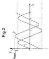
- Hall sensors can have a certain offset voltage U offset , which is superimposed as a DC voltage component at the output of the Hall sensor on the sine or cosine signal generated by the magnets of the rotor. This can be seen in FIG. 2, where signal 2 is shifted from signal 1 (ideal signal without offset voltage) by offset voltage U offset in the direction of the ordinate.
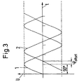
- Hall sensors can also have a phase shift offset ( ⁇ offset , as indicated in FIG. 3).
- ⁇ offset phase shift offset
- signal 2 is shifted in the direction of the abscissa in relation to signal 1 by the phase shift offset ⁇ offset .
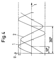
- Hall sensors can also be different Gain factor. With the same excitation by the magnets a Hall sensor therefore has an output signal from the rotor - one Output voltage U -, which is smaller in amplitude than that Amplitude of the output signal from the other Hall sensor. 4 recognizes one such example of two Hall sensors with different Gain factor: The amplitude of signal 1 of one Hall sensor is greater than the amplitude of signal 2 from the other Hall sensor.
- the distances d1 and d2 which are each the spatial distance from two magnetic poles of the same name (here: from two north poles), may vary slightly, which are magnets - viewed in the direction of the runner's movement - of different lengths.
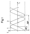
- the maximum amplitude would only come back at a time t occur that corresponds to a phase angle of 360 °.
- the Hall sensors HS1 and HS2 are (see Fig. 6) in a holder 3 in the recess 31 and 32 ideally in one Distance a arranged from each other, the at a constant distance Magnets of the rotor corresponds to a phase angle of 90 °.
- the at a constant distance Magnets of the rotor corresponds to a phase angle of 90 °.
- the one Hall sensor HS1 produces a sinusoidal output signal while from the Hall sensor HS2 a cosine output signal is generated.
- This corresponds to the ideal case (see also Fig. 1).
- phase shift offset can also hence the fact that the actual Hall sensors HS1 and HS2 are inside of the sensor housing are not exactly centered. 7 is a such case drawn, the arrow crosses each the direction and Show amount of displacement. The right sensor HS2 is therefore inside the recess 32 (not shown in Fig. 7, see Fig. 6) to the right and arranged offset to the front.
- the Hall sensors HS1 and HS2 can have different gain factors. While the reasoning may be inherent in components - i.e. the Hall sensors HS1 and HS2 point in isolation with optimal arrangement within the Depressions 31 and 32 have a different gain factor) - the different gain factor can also be determined by an oblique Installation position - in Fig. 8 e.g. of the Hall sensor HS2 within the recess 32 - be justified.
- a further disadvantage of known linear motors is that they be regularly labeled with adhesive labels that indicate which type of linear motor or which variant within a type of linear motor. Will the labeling of the adhesive labels illegible, so can often certain parameters of the linear motor either only with difficulty, or no longer at all. In such a case, the serial number is basically lost, because for a separate serial number is assigned to each motor. Especially in the case a necessary recall of linear motors, this has a disadvantageous effect, because the affected linear motors may no longer be identified can be.
- the object of the invention is to propose a linear motor that the does not have numerous disadvantages mentioned above.
- the manufacturing effort in overcoming these disadvantages so be as small as possible.
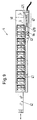
- FIG. 9 of an inventive Linear motor 4 shows the stator 40, in which several coils 41 are arranged. Furthermore, one recognizes a rotor 42, which has several magnets includes (not shown here). In the stator 40 there are also two Hall sensors 43 and 44 arranged, which each provide information about the current Give the position of the linear motor. Ideally, these are (see above) arranged so that they produce an output signal offset by 90 °, when the rotor 42 is moved in the direction of the longitudinal axis of the stator 40.
- the coils 41 in the stator 40 act in cooperation with the magnets of the rotor 42 cause or hold the rotor 42 Runner 42 firmly in a desired position.
- microelectronics 47 can be seen in the stator 40, which a memory unit 470 and a processor 471 for reading out the Storage unit 470 comprises.
- This data can with the help of a cable K transmitted to an electronic unit (not shown), which on the one hand represent the connection to higher-level control units can and on the other hand for the control or regulation of each with it connected linear motor 4 is concerned.
- This data can when connecting the linear motor 4 from the Electronics unit (not shown) read out with the help of the processor 471 become.
- the characteristic data information about an existing one Offset voltage, and / or an existing phase shift offset, and / or via different gain factors of the Hall sensors, and / or information about a non-uniform distance between neighboring ones magnetic poles of the same name of the runner so it is possible to resulting deviations in the output signals take into account or correct.
- this data must be Known electronics unit, which this data for example in a Initialization phase when connecting the linear motor 4 with the Electronics unit from processor 470 using processor 471 reads. Once the electronic unit has the corresponding data, it can also use this data to control or regulate the Take linear motor 4 into account exactly. Deviations from the Ideal case - whatever the reason for this (component inherent Tolerances, assembly tolerances, etc.) that otherwise inevitably with a certain imprecision in the control or control of the linear motor result, taken into account and corrected if necessary become.
- the permissible temperature range in which the Linear motor 4 may be operated stored in the memory unit 470 and be accessible from it.
- the electronics unit during the Operation with the help of the processor 471 certain data in the storage unit 470 writes or the processor 471 does so during operation automatically does. For example, the operating time, the number of movements of the runner 42 or information about whether the Customer has ever overloaded the linear motor 4 (recording the current one Operating temperature and in particular of excess temperatures) in which Storage unit 470 can be written into it. This can be useful in With regard to warranties or services to be provided.
- test program in the memory unit 470 is stored, which checks the linear motor 4 from time to time and if necessary, error messages or service messages are generated.
- the memory unit 470 can be used, for example, as an EEPROM memory chip (Electrically Erasable Programmable Read Only Memory). in the Linear motor 4 then no battery is necessary because the function of Only then processor 471 for reading out the memory unit 470 is necessary if the linear motor 4 is connected to the electronics unit (commissioning, initialization phase). The necessary electrical The processor 471 is then supplied by the electronics unit. The Data stored in the EEPROM memory chip remain even then received when the linear motor is separated from the electronics unit.
- EEPROM memory chip Electrically Erasable Programmable Read Only Memory
Priority Applications (1)
| Application Number | Priority Date | Filing Date | Title |
|---|---|---|---|
| EP99811075A EP1014539B1 (fr) | 1998-12-21 | 1999-11-23 | Système comportant un moteur linéaire et une unité de commande |
Applications Claiming Priority (3)
| Application Number | Priority Date | Filing Date | Title |
|---|---|---|---|
| EP98811246 | 1998-12-21 | ||
| EP98811246 | 1998-12-21 | ||
| EP99811075A EP1014539B1 (fr) | 1998-12-21 | 1999-11-23 | Système comportant un moteur linéaire et une unité de commande |
Publications (3)
| Publication Number | Publication Date |
|---|---|
| EP1014539A2 true EP1014539A2 (fr) | 2000-06-28 |
| EP1014539A3 EP1014539A3 (fr) | 2002-01-02 |
| EP1014539B1 EP1014539B1 (fr) | 2007-11-14 |
Family
ID=26152112
Family Applications (1)
| Application Number | Title | Priority Date | Filing Date |
|---|---|---|---|
| EP99811075A Expired - Lifetime EP1014539B1 (fr) | 1998-12-21 | 1999-11-23 | Système comportant un moteur linéaire et une unité de commande |
Country Status (1)
| Country | Link |
|---|---|
| EP (1) | EP1014539B1 (fr) |
Cited By (5)
| Publication number | Priority date | Publication date | Assignee | Title |
|---|---|---|---|---|
| WO2003028194A1 (fr) * | 2001-09-25 | 2003-04-03 | Copley Motion Systems Llc | Moteur lineaire avec systeme transducteur |
| EP1496603A2 (fr) * | 2003-07-10 | 2005-01-12 | Fanuc Ltd | Moteur et procéde de commande d'un moteur |
| WO2005071816A2 (fr) * | 2004-01-27 | 2005-08-04 | Copley Motion Systems Llc | Moteur lineaire et dispositif transducteur associe |
| EP1612920A2 (fr) * | 2004-07-01 | 2006-01-04 | Yamazaki, Tsunehiko | Dispositif de détection de position pour un moteur linéaire |
| CN107098249A (zh) * | 2017-06-15 | 2017-08-29 | 邱国明 | 一种无绳电梯及其安装调试方法 |
Citations (6)
| Publication number | Priority date | Publication date | Assignee | Title |
|---|---|---|---|---|
| EP0088591A2 (fr) * | 1982-03-06 | 1983-09-14 | Plessey Overseas Limited | Mémoire incorporée pour la production de produits multi-composés |
| DE3410675C1 (de) * | 1984-03-23 | 1985-10-10 | Daimler-Benz Ag, 7000 Stuttgart | Steuereinheit, für ein eine Brennkraftmaschine mit Nebenaggregaten umfassendes Antriebsaggregat eines Kraftfahrzeuges |
| EP0332607A2 (fr) * | 1988-03-10 | 1989-09-13 | VOEST-ALPINE AUTOMOTIVE Gesellschaft m.b.H. | Commande électronique pour véhicule à moteur avec moteur à combustion |
| WO1994027516A1 (fr) * | 1993-06-01 | 1994-12-08 | Synvasive Technology, Inc. | Appareil permettant d'evaluer l'utilisation d'un instrument non reutilisable |
| US5726911A (en) * | 1996-08-22 | 1998-03-10 | Csi Technology, Inc. | Electric motor monitor |
| EP0874297A1 (fr) * | 1996-10-22 | 1998-10-28 | Fanuc Ltd. | Procede et dispositif permettant de gerer un equipement connecte au dispositif de commande d'une machine de production |
Family Cites Families (1)
| Publication number | Priority date | Publication date | Assignee | Title |
|---|---|---|---|---|
| JPH0775364A (ja) * | 1993-08-31 | 1995-03-17 | Matsushita Electric Ind Co Ltd | モータ制御システム |
-
1999
- 1999-11-23 EP EP99811075A patent/EP1014539B1/fr not_active Expired - Lifetime
Patent Citations (6)
| Publication number | Priority date | Publication date | Assignee | Title |
|---|---|---|---|---|
| EP0088591A2 (fr) * | 1982-03-06 | 1983-09-14 | Plessey Overseas Limited | Mémoire incorporée pour la production de produits multi-composés |
| DE3410675C1 (de) * | 1984-03-23 | 1985-10-10 | Daimler-Benz Ag, 7000 Stuttgart | Steuereinheit, für ein eine Brennkraftmaschine mit Nebenaggregaten umfassendes Antriebsaggregat eines Kraftfahrzeuges |
| EP0332607A2 (fr) * | 1988-03-10 | 1989-09-13 | VOEST-ALPINE AUTOMOTIVE Gesellschaft m.b.H. | Commande électronique pour véhicule à moteur avec moteur à combustion |
| WO1994027516A1 (fr) * | 1993-06-01 | 1994-12-08 | Synvasive Technology, Inc. | Appareil permettant d'evaluer l'utilisation d'un instrument non reutilisable |
| US5726911A (en) * | 1996-08-22 | 1998-03-10 | Csi Technology, Inc. | Electric motor monitor |
| EP0874297A1 (fr) * | 1996-10-22 | 1998-10-28 | Fanuc Ltd. | Procede et dispositif permettant de gerer un equipement connecte au dispositif de commande d'une machine de production |
Non-Patent Citations (1)
| Title |
|---|
| PATENT ABSTRACTS OF JAPAN vol. 95, no. 6, 31. Juli 1995 (1995-07-31) & JP 07 075364 A (MATSUSHITA ELECTRIC IND CO), 17. März 1995 (1995-03-17) * |
Cited By (10)
| Publication number | Priority date | Publication date | Assignee | Title |
|---|---|---|---|---|
| WO2003028194A1 (fr) * | 2001-09-25 | 2003-04-03 | Copley Motion Systems Llc | Moteur lineaire avec systeme transducteur |
| EP1496603A2 (fr) * | 2003-07-10 | 2005-01-12 | Fanuc Ltd | Moteur et procéde de commande d'un moteur |
| EP1496603A3 (fr) * | 2003-07-10 | 2005-01-19 | Fanuc Ltd | Moteur et procéde de commande d'un moteur |
| WO2005071816A2 (fr) * | 2004-01-27 | 2005-08-04 | Copley Motion Systems Llc | Moteur lineaire et dispositif transducteur associe |
| WO2005071816A3 (fr) * | 2004-01-27 | 2005-10-20 | Copley Motion Systems Llc | Moteur lineaire et dispositif transducteur associe |
| US7656108B2 (en) | 2004-01-27 | 2010-02-02 | Copley Motion Systems Llc | Linear motor and transducer arrangement therefor |
| EP1612920A2 (fr) * | 2004-07-01 | 2006-01-04 | Yamazaki, Tsunehiko | Dispositif de détection de position pour un moteur linéaire |
| EP1612920A3 (fr) * | 2004-07-01 | 2008-07-16 | Tsunehiko Yamazaki | Dispositif de détection de position pour un moteur linéaire |
| CN107098249A (zh) * | 2017-06-15 | 2017-08-29 | 邱国明 | 一种无绳电梯及其安装调试方法 |
| CN107098249B (zh) * | 2017-06-15 | 2022-11-22 | 上海史密富智能装备股份有限公司 | 一种无绳电梯及其安装调试方法 |
Also Published As
| Publication number | Publication date |
|---|---|
| EP1014539B1 (fr) | 2007-11-14 |
| EP1014539A3 (fr) | 2002-01-02 |
Similar Documents
| Publication | Publication Date | Title |
|---|---|---|
| EP1832851B1 (fr) | Indicateur de position pour un élément de commande, moteur linéaire et procédé de fabrication d'un moteur linéaire | |
| EP0471101A1 (fr) | Procédé et dispositif pour le positionnement d'une tête magnétique sur la surface d'une mémoire magnétique | |
| EP1649331B1 (fr) | Systeme et procede pour identifier des composants d'automatisation | |
| CH649407A5 (de) | Aufzeichnungseinrichtung und kassette fuer eine solche aufzeichnungseinrichtung. | |
| DE19754843A1 (de) | Antriebsvorrichtung für ein zwischen Endstellungen bewegbares Teil eines Fahrzeugs und Verfahren zu ihrer Herstellung | |
| DE10037968B4 (de) | Elektrischer Antrieb mit Motoridentifizierung und Verfahren zur Motoridentifizierung | |
| EP1014539B1 (fr) | Système comportant un moteur linéaire et une unité de commande | |
| EP0585655B1 (fr) | Méthode et dispositif de régulation de la position d'un organe mobile | |
| EP1219867A1 (fr) | Unité de commande électronique pour une boíte de vitesses | |
| DE102020120241A1 (de) | Stellantrieb mit einem Elektromotor und Verfahren zur Positionsbestimmung eines Stellantriebes | |
| DE10118072B4 (de) | Verfahren zur Sicherung der Gültigkeit und Verwaltung von motorspezifischen Daten | |
| EP0519089A1 (fr) | Introduction de paramètres de service dans un commutateur de proximité prêt à servir | |
| DE3900866A1 (de) | Anordnung zur steuerung eines heiz- oder kuehlmediums | |
| EP0407654B1 (fr) | Appareil d'indication et procédé pour la détermination de la position absolute d'une aiquille dans l'appareil | |
| DE10327013A1 (de) | Steckkupplungssystem zum lösbaren elektrischen Verbinden eines programmierbaren Feldgeräts mit einem Feldbus oder mit einem Programmiergerät | |
| EP2469239A1 (fr) | Dispositif de mesure d'angle multi-tours | |
| DE2706653A1 (de) | Anzeigevorrichtung | |
| EP3064793A1 (fr) | Système de capteur de mouvement pour véhicules sur rail | |
| DE102005034376B4 (de) | Intelligente Sensoren/Befehlsgeber, Auswerteeinheit und System aus intelligenten Sensoren/Befehlsgebern und Auswerteeinheit | |
| DE112019001036T5 (de) | Elektrisch angetriebene Spritzgussmaschine | |
| EP2142967A1 (fr) | Système et procédé pour appeler des données caractéristiques | |
| EP0950875A1 (fr) | Dispositif de mésure de mouvements méchaniques | |
| DE4028690C1 (en) | Electrical adjusting esp. positioning drive - has electronic commutating motor drivable in forward and backward directions | |
| DE102022000345A1 (de) | Vorrichtung zum Erfassen von Bewegungen und/oder Positionen eines Gegenstandes | |
| WO2004020857A1 (fr) | Systeme et procede de positionnement axial d'un composant sur un arbre |
Legal Events
| Date | Code | Title | Description |
|---|---|---|---|
| PUAI | Public reference made under article 153(3) epc to a published international application that has entered the european phase |
Free format text: ORIGINAL CODE: 0009012 |
|
| AK | Designated contracting states |
Kind code of ref document: A2 Designated state(s): AT BE CH CY DE DK ES FI FR GB GR IE IT LI LU MC NL PT SE Kind code of ref document: A2 Designated state(s): CH DE GB IT LI |
|
| AX | Request for extension of the european patent |
Free format text: AL;LT;LV;MK;RO;SI |
|
| RAP1 | Party data changed (applicant data changed or rights of an application transferred) |
Owner name: NTI AG |
|
| PUAL | Search report despatched |
Free format text: ORIGINAL CODE: 0009013 |
|
| AK | Designated contracting states |
Kind code of ref document: A3 Designated state(s): AT BE CH CY DE DK ES FI FR GB GR IE IT LI LU MC NL PT SE |
|
| AX | Request for extension of the european patent |
Free format text: AL;LT;LV;MK;RO;SI |
|
| 17P | Request for examination filed |
Effective date: 20020316 |
|
| AKX | Designation fees paid |
Free format text: CH DE GB IT LI |
|
| 17Q | First examination report despatched |
Effective date: 20060524 |
|
| RTI1 | Title (correction) |
Free format text: SYSTEM WITH A LINEAR MOTOR AND A CONTROL UNIT |
|
| GRAP | Despatch of communication of intention to grant a patent |
Free format text: ORIGINAL CODE: EPIDOSNIGR1 |
|
| GRAS | Grant fee paid |
Free format text: ORIGINAL CODE: EPIDOSNIGR3 |
|
| GRAA | (expected) grant |
Free format text: ORIGINAL CODE: 0009210 |
|
| AK | Designated contracting states |
Kind code of ref document: B1 Designated state(s): CH DE GB IT LI |
|
| REG | Reference to a national code |
Ref country code: GB Ref legal event code: FG4D Free format text: NOT ENGLISH |
|
| REG | Reference to a national code |
Ref country code: CH Ref legal event code: EP |
|
| REF | Corresponds to: |
Ref document number: 59914554 Country of ref document: DE Date of ref document: 20071227 Kind code of ref document: P |
|
| REG | Reference to a national code |
Ref country code: CH Ref legal event code: NV Representative=s name: A. BRAUN, BRAUN, HERITIER, ESCHMANN AG PATENTANWAE |
|
| GBT | Gb: translation of ep patent filed (gb section 77(6)(a)/1977) |
Effective date: 20071212 |
|
| REG | Reference to a national code |
Ref country code: CH Ref legal event code: PFA Owner name: NTI AG Free format text: NTI AG#TECHNOPARKSTRASSE 1#8005 ZUERICH (CH) -TRANSFER TO- NTI AG#TECHNOPARKSTRASSE 1#8005 ZUERICH (CH) |
|
| PLBE | No opposition filed within time limit |
Free format text: ORIGINAL CODE: 0009261 |
|
| STAA | Information on the status of an ep patent application or granted ep patent |
Free format text: STATUS: NO OPPOSITION FILED WITHIN TIME LIMIT |
|
| 26N | No opposition filed |
Effective date: 20080815 |
|
| REG | Reference to a national code |
Ref country code: CH Ref legal event code: PCAR Free format text: NEW ADDRESS: HOLBEINSTRASSE 36-38, 4051 BASEL (CH) |
|
| PGFP | Annual fee paid to national office [announced via postgrant information from national office to epo] |
Ref country code: GB Payment date: 20141117 Year of fee payment: 16 |
|
| PGFP | Annual fee paid to national office [announced via postgrant information from national office to epo] |
Ref country code: IT Payment date: 20151106 Year of fee payment: 17 Ref country code: DE Payment date: 20151126 Year of fee payment: 17 Ref country code: CH Payment date: 20151123 Year of fee payment: 17 |
|
| GBPC | Gb: european patent ceased through non-payment of renewal fee |
Effective date: 20151123 |
|
| PG25 | Lapsed in a contracting state [announced via postgrant information from national office to epo] |
Ref country code: GB Free format text: LAPSE BECAUSE OF NON-PAYMENT OF DUE FEES Effective date: 20151123 |
|
| REG | Reference to a national code |
Ref country code: DE Ref legal event code: R119 Ref document number: 59914554 Country of ref document: DE |
|
| REG | Reference to a national code |
Ref country code: CH Ref legal event code: PL |
|
| PG25 | Lapsed in a contracting state [announced via postgrant information from national office to epo] |
Ref country code: LI Free format text: LAPSE BECAUSE OF NON-PAYMENT OF DUE FEES Effective date: 20161130 Ref country code: CH Free format text: LAPSE BECAUSE OF NON-PAYMENT OF DUE FEES Effective date: 20161130 |
|
| PG25 | Lapsed in a contracting state [announced via postgrant information from national office to epo] |
Ref country code: IT Free format text: LAPSE BECAUSE OF NON-PAYMENT OF DUE FEES Effective date: 20161123 |
|
| PG25 | Lapsed in a contracting state [announced via postgrant information from national office to epo] |
Ref country code: DE Free format text: LAPSE BECAUSE OF NON-PAYMENT OF DUE FEES Effective date: 20170601 |