EP1014261A1 - Instruction look-ahead system and method - Google Patents
Instruction look-ahead system and method Download PDFInfo
- Publication number
- EP1014261A1 EP1014261A1 EP99410182A EP99410182A EP1014261A1 EP 1014261 A1 EP1014261 A1 EP 1014261A1 EP 99410182 A EP99410182 A EP 99410182A EP 99410182 A EP99410182 A EP 99410182A EP 1014261 A1 EP1014261 A1 EP 1014261A1
- Authority
- EP
- European Patent Office
- Prior art keywords
- instruction
- counter
- register
- value
- execution
- Prior art date
- Legal status (The legal status is an assumption and is not a legal conclusion. Google has not performed a legal analysis and makes no representation as to the accuracy of the status listed.)
- Withdrawn
Links
Images
Classifications
-
- G—PHYSICS
- G06—COMPUTING OR CALCULATING; COUNTING
- G06F—ELECTRIC DIGITAL DATA PROCESSING
- G06F9/00—Arrangements for program control, e.g. control units
- G06F9/06—Arrangements for program control, e.g. control units using stored programs, i.e. using an internal store of processing equipment to receive or retain programs
- G06F9/30—Arrangements for executing machine instructions, e.g. instruction decode
- G06F9/38—Concurrent instruction execution, e.g. pipeline or look ahead
- G06F9/3836—Instruction issuing, e.g. dynamic instruction scheduling or out of order instruction execution
- G06F9/3838—Dependency mechanisms, e.g. register scoreboarding
-
- G—PHYSICS
- G06—COMPUTING OR CALCULATING; COUNTING
- G06F—ELECTRIC DIGITAL DATA PROCESSING
- G06F9/00—Arrangements for program control, e.g. control units
- G06F9/06—Arrangements for program control, e.g. control units using stored programs, i.e. using an internal store of processing equipment to receive or retain programs
- G06F9/30—Arrangements for executing machine instructions, e.g. instruction decode
- G06F9/38—Concurrent instruction execution, e.g. pipeline or look ahead
- G06F9/3836—Instruction issuing, e.g. dynamic instruction scheduling or out of order instruction execution
Definitions
- This invention relates to execution of instruction sets in a computer, and more particularly, to a method and apparatus for executing certain instruction sets while waiting to execute other instruction sets.
- Computers operate by executing instructions.
- the speed at which a computer can execute an instruction set determines how rapidly the computer can execute its operations through a sequence of steps.
- computers advance by executing an instruction after which the subsequent instruction of the set of the operating code is executed. This has the disadvantage that if a particular instruction set requires significant time for execution, that other instruction sets cannot be executed at the same time.
- a computer system is organized to permit execution of multiple instructions in a rapid sequence while ensuring that no instruction is executed until the proper time.
- Each instruction is a part of a set of instructions.
- Each instruction within the set has associated with it a code which provides information regarding the relationship of its execution to the execution of other instructions in the set.
- the code includes a look-ahead value and a counter check.
- the look-ahead value provides the number of instructions which can be executed after the current instruction which do not rely on the completion of the current instruction in order to perform the operations specified therein.
- the current instruction begins execution and prior to its completion of execution, the next instruction may also begin execution. If the next instruction requires a value from the prior instruction, such as data from memory, then the next instruction cannot begin its action until the prior instruction has completed its execution. On the other hand, the next instruction may perform tasks which do not rely on the completion of the immediate prior instruction.
- the subsequent instruction in the set can start execution and, in fact, can complete its execution prior to the previous instruction having completed its execution.
- the look-ahead code provides the number of instructions beyond the current instruction which can be executed before it has completed being executed.
- a counter check code checks the value of a counter associated with the register in which the memory instruction is stored. If the counter is 0, then the instruction set has permission to execute and proceed. On the other hand, if the counter value is not 0, then the instruction does not have permission to execute and waits until its counter is 0 before it executes.
- the look-ahead value of an instruction is used to increment the counter associated with the register at the location of the number of instruction sets ahead of the value plus 1. Thus, if the look-ahead value were 3, this means that the next three instructions can be executed before the current instruction has completed execution. However, the fourth instruction ahead of it cannot be assured of being cleared for execution until the current instruction is executed. Accordingly, the look-ahead value is used to increment a counter associated with the register four instructions ahead of the current instruction, the value 4 being n+1 where n is the look-ahead value. When the current instruction completes its execution, it decrements the same counter by 1. Therefore, when the time comes for the execution of the instruction stored in the register associated with that counter, the counter value will have been decremented by 1 and, if the count is 0, the instruction will be executed.
- the present invention provides the advantage that instructions can be executed rapidly, with the start of execution of subsequent instructions beginning before a prior instruction has been completely executed. This significantly increases the speed of operation of the computer.
- a further advantage is provided that in the event subsequent instructions do not rely on the completion of a prior instruction that may execute completely while a prior instruction is still in operation.
- a method and system are provided to delay execution of the current instruction until the system is ensured that all related prior instructions have been completed. Therefore, the reliability of the system is enhanced while still significantly increasing the speed of operation.
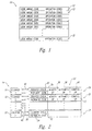
- Figure 1 is a graphical representation of a register storing a set of instructions according to principles of the present invention.
- Figure 2 is a block diagram schematic of a counter and a register according to principles of the present invention.
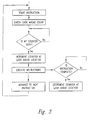
- FIG. 3 is a flowchart of operation of the present invention.
- Figure 1 shows the structure of a set of instructions 10.
- Each set of instruction 10 includes a group of individual instructions 12.
- Each instruction 12 includes at least two types of codes, a look-ahead code and various operation codes.
- the instruction may include a number of other codes which need not be discussed with regards to the present invention.
- the look-ahead code is normally at the front portion of the instruction. In one embodiment, it is the first code encountered when operation of the instruction begins. In other embodiments, it may be the second or third code. However, it is always positioned near the forward portion of the instruction 12.
- the look-ahead code provides information regarding the relationship between the current instruction and subsequent instructions, as will now be explained.
- Some instructions require a different amount of time to complete execution. Some instructions may be fairly rapid, for example, the performing of a simple arithmetic operation such as the sum of two numbers can be done very rapidly in some computer systems. In addition, the control of certain functions, such as setting the control code of performing the control operation, can also be done quite rapidly in some computer systems. On the other hand, memory operations are generally more time-consuming. The length required for execution of a memory operation may also depend on the type and location of the memory being accessed. Some instruction sets may require the retrieval of data from a memory register. If the memory register is the type having a very fast access time, then the data may be retrieved quite rapidly as compared to other memory operations.
- the memory operation may take even longer than a standard memory operation.
- the memory operation may be of the type which includes writing data to a certain memory, which normally takes longer than reading data from a particular memory location, again depending on the type of memory involved and the interaction between the memory and the other parts of the system.
- most memory operations require more time than other types of operations, such as arithmetic or control operations.
- a standard memory operation may require in the range of 100-120 clock cycles but some other operations, such as a move or an arithmetical operation can, in some instances, be completely executed in 10-20 clock cycles or less.
- the look-ahead code in each instruction contains information relevant to the amount of time expected for the execution of the current instruction and also the relationship of its execution to the execution of other instructions. If the current instruction is executing tasks which must be completed before the next subsequent instruction can be executed, then it is important that the current instruction complete its operation before the related subsequent instructions are executed. On the other hand, if the current instruction is not providing any essential information for the next subsequent instruction, then it is permissible to begin execution of the next instruction before the current instruction has completed its own execution.
- the second instruction can begin its execution and, in fact, could proceed to complete its execution prior to the previous instruction having completed its execution.
- the second or third following instruction sets include instructions such as control operations or retrieving additional data from memory which do not require the product from the first instruction or the data from memory of the second instruction, then these instructions could also begin execution prior to the first instruction having completed its own execution. Indeed, they could proceed to completion of their own execution while previous instructions are still performing their instructions.
- a subsequent instruction set can also begin execution before the immediate previous instruction has completed its own execution.
- the subsequent instruction set may complete its own execution and the next instruction begin execution prior to the then current instruction set having completed its own execution.
- the starting of execution of various instructions before the completion of a number of prior instruction can proceed for as many as desired, so long as the completion of the current instruction set is not a requirement to start execution of any subsequent instruction set. Therefore, following the start of execution of a first instruction set, subsequent instructions may also begin execution before the completion of the current instruction.
- the look-ahead code associated with each instruction provides an indication of how many subsequent instructions can begin their execution prior to completion of the current instruction, as will now be explained.
- Figure 2 is a block diagram of a hardware implementation of the concept of the present invention as explained with respect to Figure 1.
- Figure 1 illustrates a counter block 14 which is composed of a plurality of counters 16, 18, and the like, up until counter n20.
- the circuit also includes a memory register 22 which includes a plurality of individual registers 24 and 26 to n register 28.
- Each register in the memory register 22 is associated with a particular counter in the counter circuit 14.
- the first counter 16 is associated with the first register 24, the second counter 18 is associated with the second register 26, and so on with n counter 20 being associated with n register 28.
- the register 24 is also connected to each of the counters 16, 18, etc., via a counter bus 30.
- each of the registers 24, 26, etc. is connected to the counter bus 30 which provides access of each register to each of the counters 16, 18, etc., in the counter circuit 14.
- a set of instructions are stored in the memory 22, with one instruction in each respective register 24, 26, etc.
- a counter check code 32 also stored in the same register is a counter check code 32 and an increment code 34.
- the counter check code 32 checks the value in the counter associated with that particular register. In the present case, register 1 is associated with counter 1. Therefore, the value stored in counter 1 is checked. If the value is 0, then the instruction is enabled for execution.
- the communication link for the counter check 32 can be on counter bus 30 so that only a single bus is provided between the register 22 and the counter 14.
- Either of two embodiments, or further alternative embodiment which permits communication to and from the register 24 to the counter 14 and individual counters within the counter are acceptable, many suitable such connections being known in the art.
- the look-ahead code also includes an increment code 34 stored in register 24.
- the increment code 34 contains a numerical value corresponding to the number of subsequent instructions which can be executed before the execution of the current instruction is completed. This value is used as the address to a particular counter within the counter circuit 14.
- the increment code 34 provides a pointer to either increment or decrement the proper counter in register 14.
- the number of counters ahead of the current register, plus 1, is incremented by 1.
- the instruction may be of the type that executes very fast and it will be executed and completed before the system would have time to start on the next instruction. Some time is thus saved by not performing the increment and decrement.
- the increment code when the increment code is 0, then the next subsequent counter is incremented.
- This instruction may include such operations as a memory operation 36, an arithmetic operation 38, or a control operation 40.
- Each instruction may have all three of these types of operations, or only two or only one of these types of operations. They may also have other types of operations since there are many possible operations and these three are only provided as examples.
- any acceptable type of operation which is included in any instruction set for the computer system is also stored in this register 24.
- instruction sets may include all operations, the actual operation may be of the type termed a "no operation," namely, that the operation to be performed is none for that particular instruction set for a given type of operation.
- the value of the code stored as the increment code represents the number of subsequent instructions whose execution can begin before the current instruction has completed its own execution. For example, in the event the next three subsequent instructions can begin execution prior to the current instruction having completed its execution, the value stored in the increment code will be 3.
- the fourth instruction following the then current instruction may, or on the other hand, may not require completion of the instruction stored in register 24. However, if it is not assured that the instruction can begin execution prior to completion of the execution of such a previous instruction, then the code is selected to prevent execution of this instruction. Following the checking of the counter and the incrementing of the appropriate next counter, execution of the current instruction begins. Subsequently, the next instruction stored in register 26 is checked for execution. This check for execution occurs before the prior instruction has completed its execution.
- the instruction stored in register 26 checks its associated counter 2 to confirm that the count value is 0. If the count value is 0, then it can begin execution. If the count value is non-0, then it does not begin execution.
- the value in its own increment code is also checked to determine the number of following instructions which may be executed prior to its completing its own execution. Assuming, for purposes of this example that the number stored in this increment code value is 2, then the counter which is located two positions ahead of the current register, will be incremented 1. In the example provided, this will increment the same register as was incremented in the previous example so the counter at the fourth location now has a 2 stored therein.
- the instruction stored in register 26 thereafter begins execution.
- the instruction stored in the next register and associated with counter 3 then begins execution.
- increment code 34 provides the value and instructions to perform either an increment or a decrement as needed. Further, when the instructions stored in register 26 completes its execution, it will also decrement the counter it causes to be incremented using the increment code value from register 34 as the pointer to the proper counter. If the instruction in register 26 is more quickly executed than that stored in register 24, it may complete its execution even before the instruction stored in register 24 has completed its execution. In the example provided, the counter will now be at 0 and the execution of the instruction stored in this register can proceed.
- the increment code can be any value from 0 to 7 and the counters are 3-bit numbers which can count eight numbers, from 0 to 7. Accordingly, for each register it can look ahead up to seven instructions and permit execution of each of the respective instructions to begin prior to its execution being completed.
- the register 24 has rollover capability for referencing to additional counters. For example, if the n register 28 has a value stored in the increment code, then it rolls over to the next counter starting at counter 16 and goes down to the proper counter according to its value. Thus, if the code stored in register 28 is 6, it will count forward six counters plus 1, to counter number 7 and increment that counter.
- each instruction When an instruction has been completed in a particular register, then a new instruction may be stored in the same register and execution of the program continues. Thus, the instruction set which is stored in each particular register will be changed to include a new instruction set when it is no longer necessary to maintain that instruction set in the memory 22.
- Each of the new instructions will have as its part of their instruction set the increment code indicating which instructions ahead of it can being their execution before its own execution is completed. Therefore, each instruction carries with it the information necessary for continued operation according to principles of the present invention.
- Figure 3 provides a brief summary of a flowchart according to one embodiment of the present invention.
- execution of the instruction is started.
- the look-ahead count is checked and the counter at the look-ahead location is incremented.
- the instruction then checks its own counter to see if its current counter has a 0 value. If the answer is NO, then it does not perform any further execution but waits to proceed until the counter is 0. It continues to query whether the counter has reached 0 and begins execution as soon as the counter reaches 0.
- Various embodiments for the sequence of the first few steps have been disclosed herein. For example, whether the counter check occurs first followed by the increment as described with respect to Figure 2 or, on the other hand, if the increment of the look-ahead counter occurs first followed by checking the value of the associated counter both fall within the scope of the present invention.
- the program proceeds to start execution of the next instruction. This returns to the start of the flowchart as shown in Figure 3. This can continue for many instructions, so that 7 or 16 or more instructions have begun execution before a current instruction is finished.
- the value of the look-ahead code will specify the number which can be started. Once the current instruction has completed its execution, it decrements the counter at its look-ahead location.
- the sequence of instructions and the speed of operation is selected such that each time an instruction is ready for operation, its own counter will either be 0, or will have been decremented sufficiently that it will soon reach 0 so that operation can proceed quickly and smoothly.
- the present invention provides a significant advantage that execution of a number of instructions can begin before a prior instruction has completed its execution. Many instructions can be executed simultaneously. Once the instruction has completed its execution, it decrements the counter at the correct location and, if all instructions which have caused an increment of that counter have also been completed, then the counter will be decremented to 0 and that instruction can be executed when the computer reaches it as the next instruction set to start execution.
- the start of the execution of each of the instructions can occur very rapidly, so that many instructions that have started to execute may do so immediately. As soon as an instruction is cleared for execution, it will begin to be executed, thus significantly speeding up the operation of the computer and the completion of the full instruction set.
Landscapes
- Engineering & Computer Science (AREA)
- Software Systems (AREA)
- Theoretical Computer Science (AREA)
- Physics & Mathematics (AREA)
- General Engineering & Computer Science (AREA)
- General Physics & Mathematics (AREA)
- Advance Control (AREA)
Applications Claiming Priority (2)
| Application Number | Priority Date | Filing Date | Title |
|---|---|---|---|
| US09/221,187 US6311266B1 (en) | 1998-12-23 | 1998-12-23 | Instruction look-ahead system and hardware |
| US221187 | 1998-12-23 |
Publications (1)
| Publication Number | Publication Date |
|---|---|
| EP1014261A1 true EP1014261A1 (en) | 2000-06-28 |
Family
ID=22826734
Family Applications (1)
| Application Number | Title | Priority Date | Filing Date |
|---|---|---|---|
| EP99410182A Withdrawn EP1014261A1 (en) | 1998-12-23 | 1999-12-22 | Instruction look-ahead system and method |
Country Status (3)
| Country | Link |
|---|---|
| US (1) | US6311266B1 (enExample) |
| EP (1) | EP1014261A1 (enExample) |
| JP (1) | JP2000194556A (enExample) |
Families Citing this family (5)
| Publication number | Priority date | Publication date | Assignee | Title |
|---|---|---|---|---|
| GB2447907B (en) * | 2007-03-26 | 2009-02-18 | Imagination Tech Ltd | Processing long-latency instructions in a pipelined processor |
| US7779234B2 (en) * | 2007-10-23 | 2010-08-17 | International Business Machines Corporation | System and method for implementing a hardware-supported thread assist under load lookahead mechanism for a microprocessor |
| US9471317B2 (en) * | 2012-09-27 | 2016-10-18 | Texas Instruments Deutschland Gmbh | Execution of additional instructions in conjunction atomically as specified in instruction field |
| US9400653B2 (en) * | 2013-03-14 | 2016-07-26 | Samsung Electronics Co., Ltd. | System and method to clear and rebuild dependencies |
| US10185568B2 (en) | 2016-04-22 | 2019-01-22 | Microsoft Technology Licensing, Llc | Annotation logic for dynamic instruction lookahead distance determination |
Citations (2)
| Publication number | Priority date | Publication date | Assignee | Title |
|---|---|---|---|---|
| US5555384A (en) * | 1989-12-01 | 1996-09-10 | Silicon Graphics, Inc. | Rescheduling conflicting issued instructions by delaying one conflicting instruction into the same pipeline stage as a third non-conflicting instruction |
| US5712996A (en) * | 1993-03-15 | 1998-01-27 | Siemens Aktiengesellschaft | Process for dividing instructions of a computer program into instruction groups for parallel processing |
Family Cites Families (5)
| Publication number | Priority date | Publication date | Assignee | Title |
|---|---|---|---|---|
| US5933627A (en) * | 1996-07-01 | 1999-08-03 | Sun Microsystems | Thread switch on blocked load or store using instruction thread field |
| US6233599B1 (en) * | 1997-07-10 | 2001-05-15 | International Business Machines Corporation | Apparatus and method for retrofitting multi-threaded operations on a computer by partitioning and overlapping registers |
| US6223208B1 (en) * | 1997-10-03 | 2001-04-24 | International Business Machines Corporation | Moving data in and out of processor units using idle register/storage functional units |
| US6105051A (en) * | 1997-10-23 | 2000-08-15 | International Business Machines Corporation | Apparatus and method to guarantee forward progress in execution of threads in a multithreaded processor |
| KR100280460B1 (ko) * | 1998-04-08 | 2001-02-01 | 김영환 | 데이터 처리 장치 및 이의 복수의 스레드 처리 방법 |
-
1998
- 1998-12-23 US US09/221,187 patent/US6311266B1/en not_active Expired - Lifetime
-
1999
- 1999-12-22 JP JP11365694A patent/JP2000194556A/ja active Pending
- 1999-12-22 EP EP99410182A patent/EP1014261A1/en not_active Withdrawn
Patent Citations (2)
| Publication number | Priority date | Publication date | Assignee | Title |
|---|---|---|---|---|
| US5555384A (en) * | 1989-12-01 | 1996-09-10 | Silicon Graphics, Inc. | Rescheduling conflicting issued instructions by delaying one conflicting instruction into the same pipeline stage as a third non-conflicting instruction |
| US5712996A (en) * | 1993-03-15 | 1998-01-27 | Siemens Aktiengesellschaft | Process for dividing instructions of a computer program into instruction groups for parallel processing |
Non-Patent Citations (1)
| Title |
|---|
| "REGISTER DATAFLOW", SUPERSCALAR MICROPROCESSOR DESIGN,US,ENGLEWOODS CLIFFS, NJ, 1 January 1991 (1991-01-01), pages 103 - 126, XP000490269 * |
Also Published As
| Publication number | Publication date |
|---|---|
| US6311266B1 (en) | 2001-10-30 |
| JP2000194556A (ja) | 2000-07-14 |
Similar Documents
| Publication | Publication Date | Title |
|---|---|---|
| US20110082952A1 (en) | Multi-reader multi-writer circular buffer memory | |
| US4393463A (en) | Insertion of character set change codes in an altered text stream | |
| US4943915A (en) | Apparatus and method for synchronization of a coprocessor unit in a pipelined central processing unit | |
| JPH0668736B2 (ja) | 2個のシステムクロックサイクルを利用する書込み動作をもったキャッシュメモリユニットを供与する装置及び方法 | |
| JPS6376034A (ja) | 多重アドレス空間制御方式 | |
| US4974143A (en) | Information processing apparatus wherein address path is used for continuous data transfer | |
| US7237043B2 (en) | System for improving PCI write performance | |
| US6311266B1 (en) | Instruction look-ahead system and hardware | |
| EP0386719A2 (en) | Partial store control circuit | |
| EP0220990B1 (en) | Buffer storage control system | |
| EP0240606A2 (en) | Pipe-line processing system and microprocessor using the system | |
| EP0180157A2 (en) | Information processing unit | |
| US4388687A (en) | Memory unit | |
| EP0287600B1 (en) | Method and device to execute two instruction sequences in an order determined in advance | |
| IE61306B1 (en) | Method and device to execute two instruction sequences in an order determined in advance | |
| EP0261947A1 (en) | Computer system | |
| EP0206335B1 (en) | Interruption method for a data processing system | |
| US3248701A (en) | Data transfer control system | |
| EP0915416A2 (en) | System for allowing a two word instruction to be executed in a single cycle and method therefor | |
| JP2740469B2 (ja) | タスク管理方式 | |
| JP3130798B2 (ja) | バス転送装置 | |
| JP2918570B2 (ja) | 中央演算処理装置 | |
| EP0252042B1 (en) | Method and apparatus for determining in a computer which of a number of programmes are allowed to utilise a rapid access memory | |
| JP3098414B2 (ja) | ロードモジュール格納方法 | |
| JP3428253B2 (ja) | シーケンサ |
Legal Events
| Date | Code | Title | Description |
|---|---|---|---|
| PUAI | Public reference made under article 153(3) epc to a published international application that has entered the european phase |
Free format text: ORIGINAL CODE: 0009012 |
|
| AK | Designated contracting states |
Kind code of ref document: A1 Designated state(s): DE FR GB |
|
| AX | Request for extension of the european patent |
Free format text: AL;LT;LV;MK;RO;SI |
|
| 17P | Request for examination filed |
Effective date: 20001215 |
|
| AKX | Designation fees paid |
Free format text: DE FR GB |
|
| RAP1 | Party data changed (applicant data changed or rights of an application transferred) |
Owner name: CRAY INC. |
|
| 17Q | First examination report despatched |
Effective date: 20020129 |
|
| GRAH | Despatch of communication of intention to grant a patent |
Free format text: ORIGINAL CODE: EPIDOS IGRA |
|
| RTI1 | Title (correction) |
Free format text: INSTRUCTION LOOK-AHEAD SYSTEM AND METHOD |
|
| STAA | Information on the status of an ep patent application or granted ep patent |
Free format text: STATUS: THE APPLICATION IS DEEMED TO BE WITHDRAWN |
|
| 18D | Application deemed to be withdrawn |
Effective date: 20031024 |