EP1014245A1 - Flaschenventil mit Druckminderfunktion - Google Patents
Flaschenventil mit Druckminderfunktion Download PDFInfo
- Publication number
- EP1014245A1 EP1014245A1 EP99125258A EP99125258A EP1014245A1 EP 1014245 A1 EP1014245 A1 EP 1014245A1 EP 99125258 A EP99125258 A EP 99125258A EP 99125258 A EP99125258 A EP 99125258A EP 1014245 A1 EP1014245 A1 EP 1014245A1
- Authority
- EP
- European Patent Office
- Prior art keywords
- bottle
- closure device
- pressure
- gas
- bottle closure
- Prior art date
- Legal status (The legal status is an assumption and is not a legal conclusion. Google has not performed a legal analysis and makes no representation as to the accuracy of the status listed.)
- Withdrawn
Links
Images
Classifications
-
- F—MECHANICAL ENGINEERING; LIGHTING; HEATING; WEAPONS; BLASTING
- F17—STORING OR DISTRIBUTING GASES OR LIQUIDS
- F17C—VESSELS FOR CONTAINING OR STORING COMPRESSED, LIQUEFIED OR SOLIDIFIED GASES; FIXED-CAPACITY GAS-HOLDERS; FILLING VESSELS WITH, OR DISCHARGING FROM VESSELS, COMPRESSED, LIQUEFIED, OR SOLIDIFIED GASES
- F17C13/00—Details of vessels or of the filling or discharging of vessels
- F17C13/04—Arrangement or mounting of valves
-
- G—PHYSICS
- G05—CONTROLLING; REGULATING
- G05D—SYSTEMS FOR CONTROLLING OR REGULATING NON-ELECTRIC VARIABLES
- G05D16/00—Control of fluid pressure
- G05D16/04—Control of fluid pressure without auxiliary power
- G05D16/0402—Control of fluid pressure without auxiliary power with two or more controllers mounted in series
-
- G—PHYSICS
- G05—CONTROLLING; REGULATING
- G05D—SYSTEMS FOR CONTROLLING OR REGULATING NON-ELECTRIC VARIABLES
- G05D16/00—Control of fluid pressure
- G05D16/04—Control of fluid pressure without auxiliary power
- G05D16/06—Control of fluid pressure without auxiliary power the sensing element being a flexible membrane, yielding to pressure, e.g. diaphragm, bellows, capsule
- G05D16/063—Control of fluid pressure without auxiliary power the sensing element being a flexible membrane, yielding to pressure, e.g. diaphragm, bellows, capsule the sensing element being a membrane
- G05D16/0644—Control of fluid pressure without auxiliary power the sensing element being a flexible membrane, yielding to pressure, e.g. diaphragm, bellows, capsule the sensing element being a membrane the membrane acting directly on the obturator
- G05D16/0672—Control of fluid pressure without auxiliary power the sensing element being a flexible membrane, yielding to pressure, e.g. diaphragm, bellows, capsule the sensing element being a membrane the membrane acting directly on the obturator using several spring-loaded membranes
-
- F—MECHANICAL ENGINEERING; LIGHTING; HEATING; WEAPONS; BLASTING
- F17—STORING OR DISTRIBUTING GASES OR LIQUIDS
- F17C—VESSELS FOR CONTAINING OR STORING COMPRESSED, LIQUEFIED OR SOLIDIFIED GASES; FIXED-CAPACITY GAS-HOLDERS; FILLING VESSELS WITH, OR DISCHARGING FROM VESSELS, COMPRESSED, LIQUEFIED, OR SOLIDIFIED GASES
- F17C2201/00—Vessel construction, in particular geometry, arrangement or size
- F17C2201/01—Shape
- F17C2201/0104—Shape cylindrical
- F17C2201/0109—Shape cylindrical with exteriorly curved end-piece
-
- F—MECHANICAL ENGINEERING; LIGHTING; HEATING; WEAPONS; BLASTING
- F17—STORING OR DISTRIBUTING GASES OR LIQUIDS
- F17C—VESSELS FOR CONTAINING OR STORING COMPRESSED, LIQUEFIED OR SOLIDIFIED GASES; FIXED-CAPACITY GAS-HOLDERS; FILLING VESSELS WITH, OR DISCHARGING FROM VESSELS, COMPRESSED, LIQUEFIED, OR SOLIDIFIED GASES
- F17C2205/00—Vessel construction, in particular mounting arrangements, attachments or identifications means
- F17C2205/01—Mounting arrangements
- F17C2205/0153—Details of mounting arrangements
- F17C2205/018—Supporting feet
-
- F—MECHANICAL ENGINEERING; LIGHTING; HEATING; WEAPONS; BLASTING
- F17—STORING OR DISTRIBUTING GASES OR LIQUIDS
- F17C—VESSELS FOR CONTAINING OR STORING COMPRESSED, LIQUEFIED OR SOLIDIFIED GASES; FIXED-CAPACITY GAS-HOLDERS; FILLING VESSELS WITH, OR DISCHARGING FROM VESSELS, COMPRESSED, LIQUEFIED, OR SOLIDIFIED GASES
- F17C2205/00—Vessel construction, in particular mounting arrangements, attachments or identifications means
- F17C2205/03—Fluid connections, filters, valves, closure means or other attachments
- F17C2205/0302—Fittings, valves, filters, or components in connection with the gas storage device
- F17C2205/0308—Protective caps
-
- F—MECHANICAL ENGINEERING; LIGHTING; HEATING; WEAPONS; BLASTING
- F17—STORING OR DISTRIBUTING GASES OR LIQUIDS
- F17C—VESSELS FOR CONTAINING OR STORING COMPRESSED, LIQUEFIED OR SOLIDIFIED GASES; FIXED-CAPACITY GAS-HOLDERS; FILLING VESSELS WITH, OR DISCHARGING FROM VESSELS, COMPRESSED, LIQUEFIED, OR SOLIDIFIED GASES
- F17C2205/00—Vessel construction, in particular mounting arrangements, attachments or identifications means
- F17C2205/03—Fluid connections, filters, valves, closure means or other attachments
- F17C2205/0302—Fittings, valves, filters, or components in connection with the gas storage device
- F17C2205/0323—Valves
- F17C2205/0332—Safety valves or pressure relief valves
-
- F—MECHANICAL ENGINEERING; LIGHTING; HEATING; WEAPONS; BLASTING
- F17—STORING OR DISTRIBUTING GASES OR LIQUIDS
- F17C—VESSELS FOR CONTAINING OR STORING COMPRESSED, LIQUEFIED OR SOLIDIFIED GASES; FIXED-CAPACITY GAS-HOLDERS; FILLING VESSELS WITH, OR DISCHARGING FROM VESSELS, COMPRESSED, LIQUEFIED, OR SOLIDIFIED GASES
- F17C2205/00—Vessel construction, in particular mounting arrangements, attachments or identifications means
- F17C2205/03—Fluid connections, filters, valves, closure means or other attachments
- F17C2205/0302—Fittings, valves, filters, or components in connection with the gas storage device
- F17C2205/0382—Constructional details of valves, regulators
- F17C2205/0385—Constructional details of valves, regulators in blocks or units
Definitions
- the invention relates to a bottle closure device for a compressed gas bottle a closing element and an actuating element for actuating the Closing element, the closing element in an opening of the gas bottle closing and opening the opening of the gas bottle position can be brought.
- the object of the present invention is therefore to provide a bottle closure device develop that avoids the disadvantages mentioned above.
- Bottle closure device a device for reducing pressure is integrated, which can be activated by means of the actuating element.
- a second is preferably attached to the bottle closure device according to the invention Pressure reducer connected.
- the entire gas bottle fitting thus receives one two-stage pressure reduction. First the gas bottle pressure is compared to that in the Bottle closure device integrated device for reducing pressure, then with the second pressure reducer on the one on the Gas withdrawal connection connected consumer demanded consumption pressure decreased.
- the consumption pressure can thus be regulated more precisely and is from instantaneous bottle pressure essentially independent.
- the closing element in the opening of the gas bottle is advantageous locking position held by a force that is independent of that on the Actuator attacking force is. I.e. the closing element closes the Gas bottle always just as tight, regardless of the force with which a user for example, turns the valve wheel of the bottle closure device. Thereby damage to the locking element or seals avoided, which can otherwise occur if the user tries by force to close the bottle. On the other hand, it ensures that even with little An absolutely secure closure of the bottle is achieved because the Locking function regardless of the force acting on the actuating element is.
- the actuating element has exactly two setting positions.
- the actuating element Closing element either in the "open” position or in the "closed” position brought.
- the closing element opens the opening of the gas bottle, the in of the gas bottle prevailing by means of the in the Bottle closure device integrated pressure reducer automatically reduced.
- the degree of pressure reduction is adjustable by means of the actuating element.
- the actuation angle of the actuation button of the bottle closure device is advantageously not more than 270 °, preferably not more than 180 °, particularly preferably not more than 150 °.
- the small actuation angle enables a quick Opening and closing the bottle stopper. This will both Ease of use and the security of the overall system are increased. In case of danger the bottle can be closed with a quick movement.
- the actuating button of the bottle closure device snaps into its End positions “bottle open” and “bottle closed”.
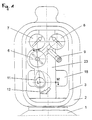
- Figure 1 is a gas bottle fitting with the invention Bottle closure device shown schematically in the front view.
- the on The fittings attached to the head of the gas bottle 1 are protected by a protective cap 2 protected against damage.
- the protective cap 2 has an access window 3, through which without removing the protective cap 2 all for the consumer relevant control and display elements of the valve are accessible and visible.
- the fitting screwed onto the gas bottle 1 consists, among other things, of a Bottle closure device 11 with integrated pressure reducer and one Actuator 5, a knob 6 for a second pressure reducer, one Manometer 7 for the pressure in the gas bottle 1 and a manometer 8 for the the gas extraction connection 9 pending consumption pressure.
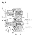
- FIG. 2 shows a section along the line K-L-M in Figure 1.
- the valve body 23 is screwed gas-tight into the bottle 1.
- a central bore runs through the valve body 23 along the bottle axis 24, with which the bottle closure device 11 and the manometer 7 in connection stand.
- the bore 24 is in its upper area by a safety valve completed, which an undesirable escape of gas from the bottle 1 prevented.
- the bottle closure device 11 has an actuating element 5 with which one axially movable spindle 27 is connected in a steep thread.
- the spindle 27 is in operative connection with a closing element 71.
- the closing element 71 is biased by springs 72 and 73.
- the actuating element 5 is designed as a lever. By turning the lever 5 around at an angle 12 of 180 °, the closing element 71 is from the open to the brought closed position. In the latter position, the closing element 71 pressed against the sealing surface to the channel 74 due to the spring force 72. A Damage to the closing element 71 by violent actuation of the lever 5 locked out. Should the bottle closure device 11 tear off, the spring 72, the closing element 71 is automatically in the brought closed position.
- the closing element 71 is affected by the pressure of the channel 24 high-pressure gas flowing in from the gas bottle and the spring force of two springs 72, 73 acted upon.
- the spring preloads are set so that the gas pressure in the bottle is reduced from 200 or 300 bar to about 30 bar.
- the entire system thus receives a two-stage pressure control, which means that Consumption pressure can be regulated more precisely.
- the influence of the current Bottle pressure on the regulated consumption pressure is essentially switched off.
- the bottle closure device 11 can also be used variable pressure reducing function can be performed.
- variable pressure reducing function can be performed.
- the spring preload 73 can be varied and the pressure of the through the gas flowing through the channel 74 released by the closing element 71 and thus the pressure of the gas supplied to the consumer can be adjusted.
Abstract
Die Erfindung betrifft eine Flaschenverschlußvorrichtung (11) für eine Druckgasflasche (1) mit einem Schließelement (71) und einem Betätigungselement (5) zum Betätigen des Schließelementes (71). Das Schließelement (71) wird dabei entweder in eine die Öffnung der Gasflasche (1) verschließende oder in eine die Öffnung der Gasflasche (1) freigebende Position gebracht. In die Flaschenverschlußvorrichtung (11) ist eine Vorrichtung zur Druckminderung integriert ist, welche mittels des Betätigungselementes (5) aktivierbar ist . <IMAGE>
Description
Die Erfindung betrifft eine Flaschenverschlußvorrichtung für eine Druckgasflasche mit
einem Schließelement und einem Betätigungselement zum Betätigen des
Schließelementes, wobei das Schließelement in eine die Öffnung der Gasflasche
verschließende und eine die Öffnung der Gasflasche freigebende Position bringbar ist.
Bei den üblichen Gasflaschenarmaturen ist in den Flaschenkopf ein Flaschenventil
zum Öffnen und Schließen der Flasche eingeschraubt. Mit dem Flaschenventil wird ein
Druckminderer verbunden, an den sich ein Gasentnahmestutzen anschließt. In der
Regel sind noch Manometer für den Flaschendruck und den Verbrauchsdruck
vorgesehen. Der Druck des an dem Gasentnahmestutzen entnommenen Gases, der
Verbrauchsdruck, ist in bestimmten Grenzen vom momentanen Flaschendruck
abhängig. Diese Abhängigkeit ist, insbesondere bei Gasanwendungen, bei denen ein
sehr stabiler Druck sichergestellt werden muß, von Nachteil.
Aufgabe vorliegender Erfindung ist es daher, eine Flaschenverschlußvorrichtung zu
entwickeln, die die oben genannten Nachteile vermeidet.
Diese Aufgabe wird erfindungsgemäß dadurch gelöst, daß in die
Flaschenverschlußvorrichtung eine Vorrichtung zur Druckminderung integriert ist,
welche mittels des Betätigungselementes aktivierbar ist.
Die Kombination einer Flaschenverschlußvorrichtung und einer Vorrichtung zur
Druckminderung zu einem Element stellt eine preiswerte und platzsparende Lösung für
die beiden Funktionen "Verschließen bzw. Öffnen der Flasche" und "Minderung bzw.
Vorminderung des Druckes" dar.
Vorzugsweise wird an die erfindungsgemäße Flaschenverschlußvorrichtung ein zweiter
Druckminderer angeschlossen. Die gesamte Gasflaschenarmatur erhält damit eine
zweistufige Druckreduzierung. Zunächst wird der Gasflaschendruck mit der in der
Flaschenverschlußvorrichtung integrierten Vorrichtung zur Druckminderung reduziert,
anschließend mit dem zweiten Druckminderer auf den von dem an dem
Gasentnahmeanschluß angeschlossenen Verbraucher geforderten Verbrauchsdruck
verringert. Der Verbrauchsdruck kann somit genauer geregelt werden und ist vom
momentanen Flaschendruck im wesentlichen unabhängig.
Mit der integrierten Vorrichtung zur Druckminderung wird vorzugsweise eine
Druckerniedrigung auf 10 bis 40 bar, besonders bevorzugt auf 20 bis 30 bar, erreicht.
Von Vorteil wird das Schließelement in der die Öffnung der Gasflasche
verschließenden Position von einer Kraft gehalten, die unabhängig von der an dem
Betätigungselement angreifenden Kraft ist. D.h. das Schließelement verschließt die
Gasflasche immer genauso dicht, unabhängig von der Kraft, mit der ein Benutzer
beispielsweise das Ventilrad der Flaschenverschlußvorrichtung zudreht. Dadurch
werden zum einen Beschädigungen an dem Schließelement oder an Dichtungen
vermieden, die ansonsten auftreten können, wenn der Benutzer mit Gewalt versucht,
die Flasche zu verschließen. Zum anderen ist sichergestellt, daß auch mit geringem
Kraftaufwand ein absolut sicherer Verschluß der Flasche erreicht wird, da die
Schließfunktion unabhängig von der an dem Betätigungselement angreifenden Kraft
ist.
In einer einfachen und günstigen Ausgestaltung besitzt das Betätigungselement genau
zwei Einstellpositionen. Durch Betätigen des Betätigungselementes wird das
Schließelement entweder in die Position "offen" oder in die Stellung "geschlossen"
gebracht. Wenn das Schließelement die Öffnung der Gasflasche freigibt, wird der in
der Gasflasche herrschende Flaschendruck mittels des in die
Flaschenverschlußvorrichtung integrierten Druckminderers automatisch reduziert.
Es hat sich als besonders vorteilhaft erwiesen, wenn der Grad der Druckminderung
mittels des Betätigungselementes einstellbar ist. Durch das Betätigungselement der
Flaschenverschlußvorrichtung wird somit einerseits die Gasflasche verschlossen oder
geöffnet, andererseits bei geöffneter Gasflasche eingestellt, wie stark der
Flaschendruck gemindert wird.
Der Betätigungswinkel des Betätigungsknopfes der Flaschenverschlußvorrichtung
beträgt von Vorteil nicht mehr als 270°, bevorzugt nicht mehr als 180°, besonders
bevorzugt nicht mehr als 150°. Der geringe Betätigungswinkel ermöglicht ein schnelles
Öffnen und Schließen der Flaschenverschlußvorrichtung. Dadurch werden sowohl der
Bedienkomfort als auch die Sicherheit des Gesamtsystems erhöht. Im Gefahrenfall
kann die Flasche mir einem schnellen Handgriff verschlossen werden.
Vorzugsweise rastet der Betätigungsknopf der Flaschenverschlußvorrichtung in seinen
Endpositionen "Flasche offen" und "Flasche geschlossen" ein.
Sowohl aus Platzgründen als auch aus ergonomischer Sicht hat sich ein Drehknopf zur
Betätigung der Flaschenverschlußvorrichtung als günstig erwiesen.
Die Erfindung sowie weitere Einzelheiten der Erfindung werden im folgenden anhand
von in den Zeichnungen dargestellten Ausführungsbeispielen näher erläutert Hierbei
zeigen:
- Figur 1
- eine Ausführungsform der erfindungsgemäßen Gasflaschenarmatur,
- Figur 2
- einen Schnitt entlang der Linie K-L-M in Figur 1.
In Figur 1 ist eine Gasflaschenarmatur mit der erfindungsgemäßen
Flaschenverschlußvorrichtung schematisch in der Vorderansicht dargestellt. Die auf
dem Kopf der Gasflasche 1 angebrachten Armaturen sind durch eine Schutzkappe 2
gegen Beschädigungen geschützt. Die Schutzkappe 2 besitzt ein Zugangsfenster 3,
durch welches ohne Entfernung der Schutzkappe 2 sämtliche für den Verbraucher
relevanten Bedien- und Anzeigeelemente der Armatur zugänglich und einsehbar sind.
Die auf die Gasflasche 1 aufgeschraubte Armatur besteht unter anderem aus einer
Flaschenverschlußvorrichtung 11 mit integriertem Druckminderer und einem
Betätigungselement 5, einem Einstellknopf 6 für einen zweiten Druckminderer, einem
Manometer 7 für den Druck in der Gasflasche 1 und einem Manometer 8 für den an
dem Gasentnahmeanschluß 9 anstehenden Verbrauchsdruck.
Die Gasarmatur ist in Figur 2 im Detail dargestellt. Figur 2 zeigt einen Schnitt entlang
der Linie K-L-M in Figur 1. Der Ventilkörper 23 ist gasdicht in die Flasche 1 geschraubt.
Durch den Ventilkörper 23 verläuft entlang der Flaschenachse eine zentrale Bohrung
24, mit der die Flaschenverschlußvorrichtung 11 und das Manometer 7 in Verbindung
stehen. Die Bohrung 24 wird in ihrem oberen Bereich durch ein Sicherungsventil
abgeschlossen, welches ein unerwünschtes Entweichen von Gas aus der Flasche 1
verhindert.
Die Flaschenverschlußvorrichtung 11 weist ein Betätigungselement 5 auf, mit dem eine
in einem steilen Gewinde axial bewegbare Spindel 27 verbunden ist. Die Spindel 27
steht mit einem Schließelement 71 in Wirkverbindung. Das Schließelement 71 wird
über die Federn 72 und 73 vorgespannt.
Das Betätigungselement 5 ist als Hebel ausgeführt. Durch Umlegen des Hebels 5 um
einen Winkel 12 von 180° wird das Schließelement 71 von der geöffneten in die
geschlossene Position gebracht. In letzterer Position wird das Schließelement 71
aufgrund der Federkraft 72 gegen die Dichtfläche zu dem Kanal 74 gedrückt. Eine
Beschädigung des Schließelementes 71 durch gewaltsames Betätigen des Hebels 5 ist
ausgeschlossen. Sollte bei einem Unfall die Flaschenverschlußvorrichtung 11
abreißen, so wird durch die Feder 72 das Schließelement 71 automatisch in die
geschlossene Stellung gebracht.
Im geöffneten Zustand wird das Schließelement 71 von dem Druck des über Kanal 24
aus der Gasflasche einströmenden Hochdruckgases und der Federkraft zweier Federn
72, 73 beaufschlagt. Die Federvorspannungen sind so eingestellt, daß der Gasdruck in
der Flasche von 200 oder 300 bar auf etwa 30 bar abgesenkt wird.
Durch Umlegen des Hebels 5 in die Position "Schließen" wird das Schließelement 71
so verschoben, daß der Kanal 74 verschlossen ist. In der Position "Öffnen" gibt das
Schließelement 71 dagegen einen bestimmten Querschnitt des Kanals 74 frei, wodurch
der Gasdruck entsprechend abgesenkt werden kann. Der Hebel 5 erlaubt somit das
Umschalten zwischen den Funktionen "Schließen der Flasche" und "Öffnen der
Flasche mit erster Druckreduzierung".
Das Gesamtsystem erhält damit eine zweistufige Druckregelung, wodurch der
Verbrauchsdruck genauer geregelt werden kann. Der Einfluß des momentanen
Flaschendrucks auf den geregelten Verbrauchsdruck wird im wesentlichen
ausgeschalten.
In einer bevorzugten Variante kann die Flaschenverschlußvorrichtung 11 auch mit
veränderlicher Druckminderfunktion ausgeführt werden. In diesem Fall kann durch
Drehen an dem Hebel 5 die Federvorspannung 73 variiert werden und der Druck des
durch den von dem Schließelement 71 freigegebenen Kanal 74 strömenden Gases
und somit der Druck des dem Verbraucher zugeführten Gases eingestellt werden.
Claims (9)
- Flaschenverschlußvorrichtung (11) für eine Druckgasflasche (1) mit einem Schließelement (71) und einem Betätigungselement (5) zum Betätigen des Schließelementes (71), wobei das Schließelement (71) in eine die Öffnung der Gasflasche (1) verschließende und eine die Öffnung der Gasflasche freigebende Position bringbar ist, dadurch gekennzeichnet, daß in die Flaschenverschlußvorrichtung (11) eine Vorrichtung zur Druckminderung integriert ist, welche mittels des Betätigungselementes (5) aktivierbar ist.
- Flaschenverschlußvorrichtung nach Anspruch 1, dadurch gekennzeichnet, daß eine Vorrichtung zur Druckminderung auf 10 bis 40 bar, bevorzugt auf 20 bis 30 bar, vorgesehen ist.
- Flaschenverschlußvorrichtung nach einem der Ansprüche 1 oder 2, dadurch gekennzeichnet, daß die das Schließelement (71) in der die Öffnung der Gasflasche (1) verschließenden Position haltende Kraft unabhängig von der an dem Betätigungselement angreifenden Kraft ist.
- Flaschenverschlußvorrichtung nach einem der Ansprüche 1 bis 3, dadurch gekennzeichnet, daß das Betätigungselement (5) zwei Einstellpositionen besitzt.
- Flaschenverschlußvorrichtung nach einem der Ansprüche 1 bis 3, dadurch gekennzeichnet, daß der Grad der Druckminderung mittels des Betätigungselementes (5) einstellbar ist.
- Flaschenverschlußvorrichtung nach einem der Ansprüche 1 bis 5, dadurch gekennzeichnet, daß der Betätigungswinkel (12) des Betätigungselements (5) nicht mehr als 270°, bevorzugt nicht mehr als 180°, besonders bevorzugt nicht mehr als 150° beträgt.
- Flaschenverschlußvorrichtung nach einem der Ansprüche 1 bis 6, dadurch gekennzeichnet, daß das Betätigungselement (5) in seinen Endpositionen einrastet.
- Flaschenverschlußvorrichtung nach einem der Ansprüche 1 bis 7, dadurch gekennzeichnet, daß das Betätigungselement (5) als Drehknopf ausgebildet ist.
- Gasflaschenarmatur mit einer Flaschenverschlußvorrichtung nach einem der Ansprüche 1 bis 8, dadurch gekennzeichnet, daß mit der Vorrichtung zur Druckminderung eine zweite Vorrichtung zur Druckminderung verbunden ist.
Priority Applications (1)
| Application Number | Priority Date | Filing Date | Title |
|---|---|---|---|
| EP99125258A EP1014245A1 (de) | 1998-12-18 | 1999-12-17 | Flaschenventil mit Druckminderfunktion |
Applications Claiming Priority (7)
| Application Number | Priority Date | Filing Date | Title |
|---|---|---|---|
| DE19858746 | 1998-12-18 | ||
| DE19858746 | 1998-12-18 | ||
| DE19915860A DE19915860A1 (de) | 1998-12-18 | 1999-04-08 | Flaschenventil mit Druckminderfunktion |
| EP99106956 | 1999-04-08 | ||
| EP99106956 | 1999-04-08 | ||
| DE19915860 | 1999-04-08 | ||
| EP99125258A EP1014245A1 (de) | 1998-12-18 | 1999-12-17 | Flaschenventil mit Druckminderfunktion |
Publications (1)
| Publication Number | Publication Date |
|---|---|
| EP1014245A1 true EP1014245A1 (de) | 2000-06-28 |
Family
ID=27438904
Family Applications (1)
| Application Number | Title | Priority Date | Filing Date |
|---|---|---|---|
| EP99125258A Withdrawn EP1014245A1 (de) | 1998-12-18 | 1999-12-17 | Flaschenventil mit Druckminderfunktion |
Country Status (1)
| Country | Link |
|---|---|
| EP (1) | EP1014245A1 (de) |
Citations (5)
| Publication number | Priority date | Publication date | Assignee | Title |
|---|---|---|---|---|
| EP0308875A2 (de) * | 1987-09-21 | 1989-03-29 | Praxair Technology, Inc. | Hochdruckregelventil |
| EP0428901A1 (de) * | 1989-11-21 | 1991-05-29 | Luxembourg Patent Company S.A. | Neutralisierbares Reduzierventil |
| US5123409A (en) * | 1990-06-05 | 1992-06-23 | Scott Specialty Gases, Inc. | Emergency oxygen supply system |
| EP0581718A1 (de) * | 1992-04-14 | 1994-02-02 | Repsol-Butano, S.A. | Verbesserte Drosselregler für Flüssiggasflaschen |
| EP0845729A2 (de) * | 1993-06-03 | 1998-06-03 | Taema | Steuereinheit für Gasverteilung und mit einer solchen Einheit ausgestattete Flasche |
-
1999
- 1999-12-17 EP EP99125258A patent/EP1014245A1/de not_active Withdrawn
Patent Citations (5)
| Publication number | Priority date | Publication date | Assignee | Title |
|---|---|---|---|---|
| EP0308875A2 (de) * | 1987-09-21 | 1989-03-29 | Praxair Technology, Inc. | Hochdruckregelventil |
| EP0428901A1 (de) * | 1989-11-21 | 1991-05-29 | Luxembourg Patent Company S.A. | Neutralisierbares Reduzierventil |
| US5123409A (en) * | 1990-06-05 | 1992-06-23 | Scott Specialty Gases, Inc. | Emergency oxygen supply system |
| EP0581718A1 (de) * | 1992-04-14 | 1994-02-02 | Repsol-Butano, S.A. | Verbesserte Drosselregler für Flüssiggasflaschen |
| EP0845729A2 (de) * | 1993-06-03 | 1998-06-03 | Taema | Steuereinheit für Gasverteilung und mit einer solchen Einheit ausgestattete Flasche |
Similar Documents
| Publication | Publication Date | Title |
|---|---|---|
| EP1182104B1 (de) | Vorrichtung zur Verriegelung der Lenkspindel eines Fahrzeuges | |
| EP0296618B1 (de) | Selbstschliessender Kraftstoffbehälterverschluss | |
| DE3525769A1 (de) | Spannvorrichtung zum einspannen eines dental-bohrers | |
| DE60302474T2 (de) | Ventil für Druckbehälter | |
| EP2719932A1 (de) | Steigendes Handventil mit Hubbegrenzung | |
| EP3411547B1 (de) | Vorreiberverschluss mit einem in unterschiedlicher höhe an einer schliesswelle fixierbaren verschlusselement | |
| DE102010063291B4 (de) | Sicherheitsverschluss für einen Behälter, dessen Öffnung mit einem Deckel verschließbar ist | |
| EP1745231A1 (de) | Kupplung für eine druckgasflasche | |
| EP2256766A1 (de) | Brückenkontaktsystem | |
| DE19915860A1 (de) | Flaschenventil mit Druckminderfunktion | |
| WO2018145693A1 (de) | Kraftfahrzeugtürschloss | |
| EP1014245A1 (de) | Flaschenventil mit Druckminderfunktion | |
| EP1254040B1 (de) | Sicherungseinrichtung | |
| DE19911246B4 (de) | Feuerschutz-Absperrvorrichtung | |
| EP1440448A1 (de) | Tür-vorrichtung für einen isolator | |
| DE102010023574A1 (de) | Eckventil | |
| DE19926043B4 (de) | Verdrehsicherungseinrichtung | |
| EP1516829B1 (de) | Sprühkopf für einen Aerosolbehälter | |
| DE4005243A1 (de) | Drucktastenanordnung | |
| EP1187681B1 (de) | Pressluftdüse | |
| EP1013986B1 (de) | Gasflaschenarmatur | |
| DE10311449B4 (de) | Abschlussvorrichtung für einen Brandabschnitt | |
| EP0904845B1 (de) | Abschaltpistole für ein Hochdruckreinigungsgerät mit Antiverdreheinrichtung für den Hochdruckschlauch | |
| DE10159510A1 (de) | Vereinfachte Sicherungseinrichtung für Gasanwendungsanlagen | |
| EP4194099A1 (de) | Kapselhalter zur aufnahme einer gaskapsel |
Legal Events
| Date | Code | Title | Description |
|---|---|---|---|
| PUAI | Public reference made under article 153(3) epc to a published international application that has entered the european phase |
Free format text: ORIGINAL CODE: 0009012 |
|
| AK | Designated contracting states |
Kind code of ref document: A1 Designated state(s): AT BE CH CY DE DK ES FI FR GB GR IE IT LI LU MC NL PT SE |
|
| AX | Request for extension of the european patent |
Free format text: AL;LT;LV;MK;RO;SI |
|
| AKX | Designation fees paid | ||
| STAA | Information on the status of an ep patent application or granted ep patent |
Free format text: STATUS: THE APPLICATION IS DEEMED TO BE WITHDRAWN |
|
| 18D | Application deemed to be withdrawn |
Effective date: 20001229 |