EP1014052B1 - Verfahren und Anordnung zum Bestimmen eines Gewichtes mit einer dynamischen Waage - Google Patents
Verfahren und Anordnung zum Bestimmen eines Gewichtes mit einer dynamischen Waage Download PDFInfo
- Publication number
- EP1014052B1 EP1014052B1 EP99250421A EP99250421A EP1014052B1 EP 1014052 B1 EP1014052 B1 EP 1014052B1 EP 99250421 A EP99250421 A EP 99250421A EP 99250421 A EP99250421 A EP 99250421A EP 1014052 B1 EP1014052 B1 EP 1014052B1
- Authority
- EP
- European Patent Office
- Prior art keywords
- value
- measuring
- weighing
- weight
- values
- Prior art date
- Legal status (The legal status is an assumption and is not a legal conclusion. Google has not performed a legal analysis and makes no representation as to the accuracy of the status listed.)
- Expired - Lifetime
Links
Images


Classifications
-
- G—PHYSICS
- G01—MEASURING; TESTING
- G01G—WEIGHING
- G01G19/00—Weighing apparatus or methods adapted for special purposes not provided for in the preceding groups
- G01G19/002—Weighing apparatus or methods adapted for special purposes not provided for in the preceding groups for postal parcels and letters
- G01G19/005—Weighing apparatus or methods adapted for special purposes not provided for in the preceding groups for postal parcels and letters with electric or electronic computing means
Definitions
- the invention relates to a method for determining a weight with a dynamic balance, according to the preamble of claim 1 and an arrangement for carrying out the method according to the The preamble of claim 11.
- the solution aims in particular at fast mixed mail processing in a franking device.
- the Method is for users of mail processing systems with a dynamic balance and postage-calculating franking machine or with dynamic postage computer scales and franking devices.
- a digital balance is known from DE 37 35 036 C1, in which the analogue output signal of a load cell in an analogue / digital converter is converted into a digital signal.
- a microprocessor compares the latter with a zero value to derive the weight.
- the upstream user station can to be a scale and the downstream user station a franking machine.
- Measuring time must be a continuously moving mail piece completely from the Libra be included.
- mixed mail is the probability greater that the balance has determined a wrong measurement result.
- the Wiegemother increased and a control box to be ordered. That would be the length of the whole Mail processing system increase, what without a major upgrade but not possible. So if wrongly measured letters are not be controlled, the transport speed of Letters on the scales are reduced. These are a complicated one Control and controllable motors required.
- EP 514 107 B1 is by a control device in large and hard-to-weigh mail pieces of transport being interrupted as long as until the measurement is stable.
- Libra is near the downstream directed conveyor belt end arranged a detector, which only Letters go through for their weight by that time has been determined.
- unevenly distributed mass in the letter and higher Transport speed occur measurement errors.
- the dimensions of the weighing plate are designed to be slightly larger or the transport speed is set smaller. The throughput at Mixed mail is reduced accordingly.
- the prior art also includes a method and a device for weighing mailpieces known.
- a Postal scale with an improved response time to determine the correct postage and with an improved weighing algorithm described.
- Another task was a computer time-optimized parameter-driven Weighing evaluation, if the dynamic Balance to a system with another, especially higher Transport speed to be adjusted.
- a first parameter indicates the number of locations of memory cells in memory for the measured values.
- the memory cells in the memory area are soft- or hardware-connected as a shift register for a microprocessor.
- the microprocessor is programmed to receive the measured values make a sorting according to their size and in the corresponding to store the designated locations of the shift register.
- a measuring time interval ends when a letter leading edge on the letter exit is detected by a sensor.
- initial values and parameters for the evaluation of the measured values are stored.
- a mean measured value is first selected from the size-sorted measured values in a computing time interval and compared with the limit values for individual measuring ranges, an overload error being signaled when the maximum limit value is exceeded and it is checked when the limit values are exceeded whether the difference value of the smallest of the largest measured value is within a predetermined range, the bandwidth of the permissible vibration corresponds to the weigh plate loaded with a certain weight, the measurement is invalid if the difference value is greater than the bandwidth, and that after checking the validity of the measurement, a correction the weighing value is performed with an offset value and a value correction factor, and a transfer of a corrected weighing value to the franking machine takes place.
- the method for determining a weight with a dynamic balance is adapted to other transport speeds by determining a weight value corresponding to the weight of the mail piece, measuring the transport speed at all times by means of a suitable sensor and a parameter set corresponding to one of a plurality of transport speed ranges for the evaluation of the Wiegemeß substances will pretend. By interpolation of parameter sets at intermediate speeds an even better adaptation is achieved.
- the scale comprises a transport device, a weighing plate, a Load cell, sensors, interfaces and an electronic control unit, which in addition to a control of the transport device an evaluation the measured values transmitted by the load cell, the measured value correction allowed by certain parameters and the output of a corrected weight value via an interface to the postage meter performs as well as which otherwise the drive of the transport device switches to make a Weigh.
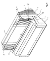
- FIG 1 is a perspective view of a dynamic Scales 10 are shown, which are for the transport of standing on the edge Letters or mailpieces A is formed.
- the latter are on one Weighing plate 6, which in a recess 11 in a rear guide wall 1 of the scale is arranged.
- Both sides of the recess 11 for the weighing plate 6 are in the rear guide wall 1 sensors S1 and S2 arranged.
- a transport device 4 In height of the lower guide wall 3 of the balance is a transport device 4 with a transport belt, which is below the Sensors S1 and S2 is deflected.
- the rear guide wall 1 is slightly inclined backwards, preferably 18 ° above the vertical out.
- the lower guide wall 3 is orthogonal to the rear and consequently also to the front cover plate 2 arranged. This creates a defined lettering position and a harmonious Adapted to the upstream and downstream devices.
- the front Cover plate 2 consists for example of Plexiglas.
- the rear end 32 the trained as an adapter to postage meter lower guide wall 3 in the mailout of Libra is designed so that the letter A during of leaving the conveyor belt is initially exposed. All mentioned Assemblies or parts are via corresponding intermediate pieces mounted on a chassis 5.
- a (covered) motor 49 has in an advantageous Manner in connection with the arrangement of the transport device.
- a compliance which shocks and vibrations damped in heavy mail pieces.
- a DC motor of the type M42x15 Gefeg drive technology suitable.
- Further Details of the structural design of the balance are the DE 19 833 767 C2 removable.
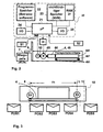
- FIG. 2 shows a block diagram of the controller 20 of a dynamic balance 10, which has a microprocessor 21, which is connected to a program memory 22, a non-volatile memory 23, a main memory 27 and interfaces for input and output 24, 25.
- the microprocessor 21 is operatively connected to a motor 49 of the conveyor 4 of the scale via a driver 26, an encoder 50 and sensors S1, S2 and a load cell 7 to receive sensor signals, encoder signals and weight data and control commands to the conveyor 4 to send.
- the transport device 4 preferably includes a DC motor 49, which is fed with DC pulses, which sets a certain speed due to the ratio of the pulse length to the pulse interval.
- the control unit of the dynamic balance depending on the evaluation of the weight measurement, the transport of the mail piece to the postage meter downstream allowed or makes a switchover to Weighing.
- the transport device 4 In the operating mode for the dynamic operation of the balance, the transport device 4 carries out a forward movement of the relevant letter within the scale downstream with a constant speed for light letters, this speed does not exceed the transport speed in the further processing station.
- the transport device of the balance Through the use of a switchable in the polarity of the pulses emitted driver 26 which is connected between the DC motor 49 and the controller 20, the transport device of the balance has a reversible drive, which with appropriate control, the transport direction of the balance in the second mode by reversing the polarity of the Motor 49 applied pulse voltage can be reversed.
- the motor 49 is connected to the drive roller 485 via a suitable gear 44.
- the transmission 44 may be both a gear transmission and a belt transmission.
- a belt (not shown), which is tensioned by means of a tensioning device 48, 481, 487 against a spring force (not shown) runs.
- the transport device the balance a reversible drive and that the control 20 includes the driver 26 which is between the drive and the controller is switched, whereby the transport direction of the balance are reversed can to perform a second measurement in the second operating mode.
- the nonvolatile memory 23 comprises a number of memory areas B1 to Bn and others for certain weight determination parameters.
- the latter are initial values for balance-type-specific basic settings.
- the initialization can be carried out via an interface of the balance.
- basic settings are made at the factory, for example by inserting a pre-programmed E 2 PROM, in the initialization phase.
- the parameters refer to the following quantities: parameter size P1 predetermined number of measured values P2 offset factor P3 Values correction factor N correction factor A1 First switch-off criterion for small weights A2 Second switch-off criterion for medium weights A3 Third shutdown criterion for large weights G1 First overload limit G2 Second overload limit G3 Third overload limit
- the load cell 7 has strain gauges with connected Evaluation circuit, which digital weight data to the microprocessor 21 delivers.
- the sensor S1 upstream serves as an inlet sensor and the sensor S2 downstream serves as a leakage sensor.
- To the sensor belongs to a known evaluation circuit, which digital signals to the microprocessor 21 outputs.
- a sensor can, for example, as Be formed photocell.
- the load cell is preferably of the type HBM PW 2G from Hottinger Baldwin Meßtechnik.
- FIG. 3 shows a representation of letter positions in the letter stream relative to the weighing plate 6 during dynamic weighing.
- the operation of the controller 20 will be explained with reference to FIG. 3 and the following table: position Action of the controller POS1 No action (letter is in front of the entrance light barrier) POS2 Start measuring time interval, deactivate engine control POS3 Measuring phase (letter is completely on the weighing plate) POS4 Stop measuring time interval, weight determination & evaluation POS5 Signal readiness (letter has left weighing plate)
- Sensors S1 and S2 are located upstream of the weighing area upstream. or downstream of the weighing plate 6. By this construction can the weighing plate 6 shortened in length by 6 to 10% be. This especially increases the cycle performance during dynamic weighing lighter mail pieces.
- position POS1 is the speed control for the Motor 49 still activated.
- the position POS2 illustrates the position of a Briefes at the start of the measurements.
- a first measuring time range T1 begins with weighing with the engine speed control 21, 26, 29, 50 deactivated.
- the letter trailing edge leaves the area of the sensor S1.
- the position POS3 clarifies the letter position in the measurement phase. None of them Sensors S1, S2 is activated.
- Position POS4 illustrates the position of a letter at the end of the measurements.
- the letter leading edge reaches the area of the sensor S2.
- the measuring time interval is ended.
- a second computing time range T2 follows, in which, in addition to the evaluation of the measurements, it is also checked whether the weight of the mail piece has been determined correctly, so that the latter can be forwarded downstream to the franking machine in a third reaction time range T3.
- the letter leaves the scale.
- the speed control for the motor 49 is activated again.
- the evaluation circuit load cell 7 is constantly, for example every 0.010 seconds digital signals to the microprocessor 21 from.
- the latter receives a signal from the sensor S1 when the letter trailing edge leaves the region of the sensor S1 and the measuring time range T1 begins.
- the speed control of the motor 49 is deactivated.
- a predetermined number of measured values M1,..., Mn is determined by the parameter P1.
- the measured values are preferably stored in a shift register.
- the P1 parameter defines a number of digits of a shift register, which stores the consecutively incoming measured values presorted in these points. Upon reaching the exit position of the leading edge of the letter, the points determined by P1 are read in parallel and digitally processed.
- a measuring time range T1 of approximately 0.150 seconds results retrospectively.
- the P1 parameter is used, for example, to preset a backward counter, which is realized in hardware / software in the controller 20.
- the microprocessor 21 has stored in a memory area of the non-volatile memory 23 a chain with the predetermined number of weighing values (15 measured value data) which can now be read out. It is advantageous if the microprocessor already performs a sorting when reading the measured values, because then a subsequent calculation time T2 is shortened.
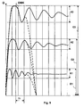
- FIG. 4 shows a time diagram about the settling of the balance.
- the black measured curve MK is obtained when a piece of mail remains longer on the weighing pan. An actually measured trace can be significantly deformed (dotted) and designed to deviate from the ideal shape.
- the dynamic measuring curve DMK shown in dashed lines.
- the weight accuracy is known to depend on the vibration behavior of the scale, the preload, the moment of inertia, the stiffness and damping exercise the greatest influence.
- the measured values, which reach the microprocessor 21 in the measuring time range T1 fluctuate around the weight value GW and are therefore further processed by the method according to the invention.
- the weight value GW is determined as quickly as possible from the measurement curve MK or DMK. It should be recognized early on, whether due to the disturbances further weighing is still worthwhile.
- the first overshoot of the measurement curve MK is above the second shutdown criterion A2 for medium weights.
- the measurement curve is evaluated by means of two windows (time and weight windows).
- the first overshoot Ü of the measurement curve MK above the second shutdown criterion A2 for medium weights is considered an error if it occurs within the two windows.
- the windows are placed in an area of the measurement curve MK or DMK, in which the first overshoot already subsides. Another condition is that the chain of the measured values M1,..., Mn during the continuous transport lies in the weight window A2. For medium weights (about 500g), a weight window A2 is set. Already the first measured values of the measuring curve DMK are in the measuring time range T1 and in the weight range of the second switching off criterion A2 and thus result in valid measured values.
- the microprocessor 21 has now stored in a further memory area B2 of the non-volatile memory 23, the size-sized chain of measured values.
- the measuring time range T1 is followed by a second computing time range T2, in which an evaluation of the measurements takes place.
- the representation of sorted weight values shown in FIG. 5 serves to clarify the further sequence.
- the first sorted weight value is the largest. It is not necessarily the first measured value measured in the time interval T1, but may for example also be caused by a spike.
- the sorting is done according to the size, so that the last sorted weight value is the smallest one.
- M m mean measured value
- the seventh gives a mean measured value M m , which as a rule, however, corresponds to a mean value only to a rough approximation and may possibly deviate considerably from such a value.
- the drawn line idealizes the actual course of gradation.
- the reduction of the magnitude of the weight values is in fact non-linear, so the seventh of the sorted weight values is not yet equated with the final measured value.
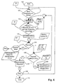
- FIG. 6 shows the flow chart for the control of the balance.
- the Microprocessor can by means of the sensor S1 at the letter entrance the letter front edge determine and start the weight determination (in step 100).
- Wiegemeßagonist are constantly supplied from the load cell 7.
- the microprocessor has the letter trailing edge at the letter entrance via the sensor S1 detected (in step 101) and starts the subroutine sort (in step 102), which will be explained in more detail with reference to FIG.
- the microprocessor recognizes by means of the sensor S2 at the mail outlet 32, the letter leading edge (in step 103).
- the one for one Detection of the number of last predetermined by the parameter P3) Measured values of elapsed time range are referred to as measuring time range T1.
- the microprocessor now forms a decision parameter E in Step 104 as difference value between the sorted largest and smallest value and starts the query for at least one overload in the Step 105.
- Measured value M7 becomes the highest overload limit G3 compared.
- a possibly existing overload fault will (in Step 111) evaluated further and the balance stopped. Is none Overload, then a further polling step 106 determines that whether the value is valid or invalid.
- a subroutine is called, which is explained in more detail with reference to FIG 8.
- the difference value E from the first M1 and fourteenth sorted measured value M14 should within of the weight range of one of the switch-off criteria A1, A2 or A3. It is for example within the second shutdown criterion A2 defined range and thus gives valid measured values.
- Step 107 determines the weighing value on branching step 107, in which a subroutine is called, which subsequently with reference to FIG 10 even closer is explained. Otherwise, if the measured values are invalid, it is written to the Step 108 branches, where the engine control is switched to the Return of the mail item to the weighing position and to a To cause awe.
- the speed n is from the encoder 50th determined and can be used for speed control.
- Step 108 is then branched back to step 102 for sorting. If the balance is not stopped (for example manually), what is in the Step 109 is queried, then from step 109 to step 101 branches back. If a stop command is detected, the end of the Operating the balance reached (step 110). For successful weight determination In step 107, the transfer takes place in a sub-step (Step 107-5) of the weighing result to the postage meter.
- FIG. 7 shows the partial schedule of sorting.
- a first sub-step 102-1 the input of weighing values is expected.
- the received Weighing successively passes through the interrogation steps 102-2, 102-3, 102-4, ..., 102-15, wherein in each query step with each of the previous measured values M1_old, M2_old, ..., M14_alt. If the new measured value is greater than the previous one, it will be replaced by the respective one Query step to a step 102-6 for storing the sorted measured values branches in the shift register.
- the microprocessor uses the Interrogation step 103 based on a signal from the sensor 2 determines whether the Sorting must be continued or can be terminated.
- Step 104 branches, with which the evaluation of the measured values starts.
- the shift register is resized at step 104 taken after first M1 and last (fourteenth) measured value M14 and a Difference E is formed by subtracting both from each other.
- the Difference E is buffered and is in the computing time interval T2 for the evaluation of the measured values.
- FIG. 8 shows the partial flow diagram overload and switch-off criterion.
- the seventh measured value is greater than the third limit value G3, then an overload is detected and the point 8 is reached. Otherwise, M7 ⁇ G3 and now it is checked whether the seventh measured value is greater as the first limit G1. If this is the case, i. G1 ⁇ M7 ⁇ G3 is before, then it is checked whether the seventh measured value is greater than the second Limit G2 is. If this is the case, i.
- G1 ⁇ G2 ⁇ M7 ⁇ G3 is present, then is branched to the query step 106-3.
- E must not be greater than the third query criterion A3 if the measured values should be valid. Otherwise, the query step 105-2 and 105-3 branches to the query step 106-1 and 106-2, respectively.
- the difference E compared with a value A1, A2 and A3 as a shutdown criterion. If the Difference E is greater than the switch-off criterion A1, A2 or A3, then the measured values are invalid (point 3). The measured values are valid (point 4), if the difference E within the shutdown criterion A1, A2 or A3 lies.
- the terms "limit values” and "shutdown criteria" are explained in FIG. 9.
- FIG. 9 shows a time diagram of the settling of the balance three different mailpiece weights.
- a high limit G3 of a mailpiece weight G for an upper weight class is the Settling of the scale usually in an area A3, which as Switch-off criterion is used.
- a different range A2 than Switch-off is used for mail piece weights of a medium weight class up to a limit value G2, a different range A2 than Switch-off.
- a further range A1 applies as the switch-off criterion.
- FIG. 10 shows the partial flow chart weighing determination.
- the buffered difference value E and a parameter P2 are called and multiplied together.
- the parameter P2 can also be set to a negative value.
- the buffered measured values M1 to Mx are added, where x is defined by the parameter P1 and, for example, is 14. With preferably 14 measured values:
- a weighing value W1 can be formed which approximately corresponds to the mean value of the measured values.
- the offset correction can be amplified by a factor of N (1 to 5) if this requires the determined weight class.
- a correction of the measured value is carried out on the basis of specific parameters P2, P3, before it is output as a corrected weight value W.
- the same load cell 7 provides a weighing speed-dependent weighing result.
- the evaluation circuit load cell 7 is constantly, for example every 0.010 seconds digital signals to the microprocessor 21 and in the measuring time range T1 15 measured value data can be stored. At a higher transport speed, the measuring time range is shortened to a measuring time range T1 '. At a constant clock frequency, more weighing values are available at the slow transport speed than at a high speed.
- the evaluation of the weighings is expediently optimized by the choice of a suitable evaluation method and the choice of suitable parameters for controlling this evaluation.
- the use of the same evaluation method is assumed in order to realize a parameter control via suitable parameter selection. It is further provided that at any time the transport speed is measured by means of a suitable sensor.
- the encoder 50 is mechanically coupled to the drive shaft of the motor 49 and provides a signal to the microprocessor 21.
- the microprocessor 21 there is an optimal parameter choice for each transport speed with which the weighing result can be further optimized.
- the multiplicity of intermediate speeds between the minimum and the maximum transport speed practically leads to a parameter map.
- This parameter map is characterized in that each parameter is assigned to each possible transport speed. As a parameter set, related parameters are referred to.
- the transport speed is entered for the system in order to preset the evaluation parameters on the basis of this.
- a correspondingly selected parameter set with initial values and parameters (P1, P2, P3, G1, G2, G3, A1, A2, A3, N) for the evaluation of the measured values is then stored in the memory areas of the nonvolatile memory 23.
- further adjustment may be provided during operation of the system. Since the transport speed is measured at any time T1, T2, T3 by means of the encoder 50 or another suitable sensor, a parameter set switching can take place after the measuring time interval T1.
- a change in the transport speed due to slip or external control leads to the adaptation of the weighing value evaluation and its optimization.
- a further embodiment makes possible an even better adaptation by interpolation of parameter sets at intermediate speeds. If a speed limit is exceeded during operation, the parameter set is automatically used, which is optimal for the current speed range. If a new parameter set is calculated parallel to the measurement by interpolation in the measuring time interval, a parameter set switching to the new parameter set can already take place after the measuring time interval T1 and thus become effective in the computing time interval T2. If a new parameter set is calculated parallel to the measuring time interval T1 and the computing time interval T2, a parameter set switching to the new parameter set can only take effect for a subsequent measuring time interval T1. After the corrected weight value W has been output to the franking machine, ie in the reaction time range T3, the changeover to the new parameter set must be completed.
- microprocessor Further processing of the valid measured values and their testing with respect to the plausibility of a weighing value and possibly a parameter set switching is done programmatically by the microprocessor.
- a microcontroller can be used instead of the microprocessor or other user-specific circuits (ASIC's) can be used.
Description
Das Verfahren zum Bestimmen eines Gewichtes mit einer dynamischen Waage wird an andere Transportgeschwindigkeiten angepaßt, indem ein dem Gewicht des Poststückes entsprechender Wiegemeßwert bestimmt, zu jeder Zeit die Transportgeschwindigkkeit mittels eines geeigneten Sensors gemessen und ein Parametersatz entsprechend einem aus einer Vielzahl an Transportgeschwindigkeitsbereichen für die Auswertung des Wiegemeßergebnisses vorgeben wird. Durch eine Interpolation von Parametersätzen bei Zwischengeschwindigkeiten wird eine noch bessere Anpassung erreicht.
- Figur 1,
- Perspektivische Ansicht einer dynamischen Waage von vorn rechts,
- Figur 2,
- Blockschaltbild der Steuerung einer dynamischen Waage,
- Figur 3,
- Darstellung von Briefpositionen im Briefstrom relativ zum Wiegeteller beim dynamischen Wiegen,
- Figur 4,
- Zeitdiagramm über das Einschwingen der Waage,
- Figur 5,
- Darstellung von sortierten Gewichtswerten,
- Figur 6,
- Flußdiagramm für die Steuerung der Waage,
- Figur 7,
- Teilablaufplan Sortieren,
- Figur 8,
- Teilablaufplan Überlast und Abschaltkriterium,
- Figur 9,
- Zeitdiagramm über das Einschwingen der Waage bei drei verschiedenen Poststückgewichten,
- Figur 10,
- Teilablaufplan Wiegewertbestimmung.
Es ist vorgesehen, daß die Steuereinheit der dynamische Waage, in Abhängigkeit von der Auswertung der Gewichtsmessung den Transport des Poststückes zur Frankiermaschine stromabwärts erlaubt oder eine Umschaltung zum Nachwiegen vornimmt.
Im Betriebsmodus für den dynamischen Betrieb der Waage führt die Transporteinrichtung 4 eine Vorwärtsbewegung des betreffenden Briefes innerhalb der Waage stromabwärts mit einer für leichte Briefe konstanten Geschwindigkeit aus, wobei diese Geschwindigkeit die Transportgeschwindigkeit in der weiteren Verarbeitungsstation nicht übersteigt. Durch den Einsatz eines in der Polarität der abgegebenen Impulse umschaltbaren Treibers 26, der zwischen Gleichstrommotor 49 und der Steuerung 20 geschaltet ist, besitzt die Transporteinrichtung der Waage einen umschaltbaren Antrieb, womit bei entsprechender Steuerung die Transportrichtung der Waage im zweiten Betriebsmodus durch Umpolung der an den Motor 49 angelegten Impulsspannung umgekehrt werden kann. Der Motor 49 ist über ein geeignetes Getriebe 44 mit der Antriebsrolle 485 verbunden. Das Getriebe 44 kann sowohl ein Zahnradgetriebe als auch ein Riemengetriebe sein. Auf der Transporteinrichtung läuft ein Riemen (nicht dargestellt), der mittels einer Spannvorrichtung 48, 481, 487 gegen eine Federkraft (nicht dargestellt) gespannt wird.
| Parameter | Größe |
| P1 | vorbestimmte Anzahl an Meßwerten |
| P2 | Offsetfaktor |
| P3 | Wertekorrekturfaktor |
| N | Korrekturfaktor |
| A1 | Erstes Abschaltkriterium für kleine Gewichte |
| A2 | Zweites Abschaltkriterium für mittlere Gewichte |
| A3 | Drittes Abschaltkriterium für große Gewichte |
| G1 | Erster Überlastgrenzwert |
| G2 | Zweiter Überlastgrenzwert |
| G3 | Dritter Überlastgrenzwert |
| Position | Aktion der Steuerung |
| POS1 | Keine Aktion (Brief ist vor der Einlauflichtschranke) |
| POS2 | Start Meßzeitintervall, Motorregelung deaktivieren |
| POS3 | Meßphase (Brief liegt komplett auf dem Wiegeteller) |
| POS4 | Stop Meßzeitintervall, Gewicht ermitteln & auswerten |
| POS5 | Bereitschaft signalisieren (Brief hat Wiegeteller verlassen) |
Ein zweiter Rechenzeitbereich T2 schließt sich an, in welchem neben der Auswertung der Messungen auch geprüft wird, ob das Gewicht des Poststückes richtig bestimmt wurde, so daß letzteres in einem dritten Reaktionszeitbereich T3 stromabwärts zur Frankiermaschine weitergeleitet werden kann. In der Position POS5 verläßt der Brief die Waage. Ab dem Reaktionszeitbereich T3 - wobei in der Regel der Schwerpunkt des Briefes den Wiegeteller 6 noch nicht verlassen hat - kann jedoch noch der Brief auf den Wiegeteller 6 mittels einer umschaltbaren Transportvorrichtung zurück transportiert werden. Außerhalb des Meßzeitbereiches T1 wird die Drehzahlregelung für den Motor 49 wieder aktivert.
Alternativ zum Schieberegister sind auch andere Speicher einsetzbar. Der P1-Parameter dient beispielsweise der Voreinstellung eines Rückwärtszählers, welcher hardware/softwaremäßig in der Steuerung 20 realisiert ist. Beim Erreichen des Zählwertes Null endet der Meßzeitbereich T1 (bei P1 = 15 nach ca. 0,150 Sekunden). Der Mikroprozessor 21 hat in einem Speicherbereich des nichtflüchtigen Speichers 23 inzwischen eine Kette mit der vorbestimmten Anzahl an Wiegewerten (15 Meßwertdaten) gespeichert, welche nun ausgelesen werden können.
Es ist vorteilhaft, wenn der Mikroprozessor beim Einlesen der Meßwerte bereits eine Sortierung vornimmt, weil dann eine anschließende Rechenzeit T2 verkürzt wird.
Eine weitere Bedingung ist, daß die Kette der Meßwerte M1,...,Mn während des kontinuierlichen Transportes im Gewichtsfenster A2 liegt. Für mittlere Gewichte (ca. 500g) wird ein Gewichtsfenster A2 festgelegt. Bereits die ersten Meßwerte der Meßkurve DMK liegen im Meßzeitbereich T1 und im Gewichtsbereich des zweiten Abschaltkriteriums A2 und ergeben somit gültige Meßwerte. Der Mikroprozessor 21 hat nun in einem weiterem Speicherbereich B2 des nichtflüchtigen Speichers 23 die nach der Größe sortierte Kette an Meßwerten gespeichert. Dem Meßzeitbereich T1 schließt sich ein zweiter Rechenzeitbereich T2 an, in welchem eine Auswertung der Messungen erfolgt.


- Sortieren (102) der Meßwerte ihrer Größe nach im Meßzeitintervall (T1) vor der Auswahl des mittig liegenden Meßwertes (Mm),
- Bildung (104) des Entscheidungsparameters (E) aus einer Differenz von sortierten Meßwerten,
- Feststellung (105) im Rechenzeitintervall (T2), daß der aus den sortierten Meßwerten mittig liegender Meßwert (Mm) in gewissen Grenzen (G1,G2,G3) liegt,
- Weiterverarbeitung (106) der gültigen Meßwerte, wobei letztere gültig sind, wenn der Entscheidungsparameter (E) die Bandbreite der Abschaltkriterien (A1,A2,A3) nicht überschreitet und
- Ausgabe (107) eines korrigierten Gewichtswertes W.
Theoretisch gibt es für jede Transportgeschwindigkeit eine optimale Parameterwahl mit der das Wiegemeßergebnis weiter optimiert werden kann. Die Vielzahl von Zwischengeschwindigkeiten zwischen der minimalen und der maximalen Transportgeschwindigkeit führt praktisch zu einem Parameterkennfeld. Dieses Parameterkennfeld ist dadurch gekennzeichnet, daß jeder möglichen Transportgeschwindigkeit ein Parametersatz zugeordnet ist. Als ein Parametersatz werden zusammengehörige Parameter bezeichnet.
| Zeichen | Parameter | V1 | V2 | V3 |
| bis 0,3 m/s | bis 0,4 m/s | bis 0,7 m/s | ||
| P1 | Meßwerteanzahl | 20 | 14 | 10 |
| P2 | Korrekturwert 1 | 0 | 0,3 | 0,5 |
| P3 | Korrekturwert 2 | 1 | 0,9995 | 0,9993 |
| N | Korrekturfaktor | 1 | 2 | 3 |
| A1 | Abschaltkriterium 1 | 8 | 10 | 15 |
| A2 | Abschaltkriterium 2 | 12 | 15 | 25 |
| A3 | Abschaltkriterium 3 | 20 | 30 | 45 |
| G1 | Grenzwert 1 | 299 | 299 | 299 |
| G2 | Grenzwert 2 | 699 | 599 | 499 |
| G3 | Grenzwert 3 | 1700 | 1500 | 1200 |
Außerdem kann eine weitere Anpassung während des Betriebes des Systems vorgesehen sein. Da zu jeder Zeit T1, T2, T3 die Transportgeschwindigkkeit mittels des Encoders 50 bzw. eines anderen geeigneten Sensors gemessen wird, kann eine Parametersatzumschaltung nach dem Meßzeitintervall T1 erfolgen. Somit führt eine Veränderung der Transportgeschwindigkeit durch Schlupf oder externe Regelung zur Anpassung der Wiegewertauswertung und deren Optimierung. Bei hohem Durchsatz an Poststücken, zum Beispiel 4000 Stück an 100-400g Briefen im Format C6 bis B4 bei der Geschwindigkeit V3 = 0,7 m/s, ist dennoch eine hohe Meßsicherheit und eine Unabhängigkeit von äußeren Störungen gegeben.
Wenn parallel zum Meßzeitintervall T1 und Rechenzeitintervall T2 ein neuer Parametersatz berechnet wird, kann eine Parametersatzumschaltung auf den neuen Parametersatz erst für ein nachfolgendes Meßzeitintervall T1 wirksam werden. Nach Ausgabe des korrigierten Gewichtswertes W an die Frankiermaschine, d.h. im Reaktionszeitbereich T3, muß die Umschaltung auf den neuen Parametersatz abgeschlossen werden.
Claims (17)
- Verfahren zum Bestimmen eines Gewichtes mit einer dynamischen Waage, mit einem Steuern der Transporteinrichtung, mit einem Liefern von Wiegewerten und mit einer Auswertung der von einer Wiegezelle übermittelten Meßwerte in einer Steuereinheit der Waage, gekennzeichnet durch eine Auswahl (102) eines mittig liegenden Meßwertes (Mm) zum Vergleich mit mindestens einem Überlastgrenzwert (G1, G2, G3) hinsichtlich einer Prüfung auf Überlastfreiheit und durch eine Bildung (104) eines Entscheidungsparameters (E) zum Vergleich mit mindestens einem Abschaltkriterium (A1, A2, A3) hinsichtlich einer Prüfung auf Gültigkeit der von der Wiegezelle übermittelten Meßwerte.
- Verfahren, nach Anspruch 1, gekennzeichnet durch die Schritte:Sortieren (102) der Meßwerte ihrer Größe nach im Meßzeitintervall (T1) vor der Auswahl eines mittig liegenden Meßwertes (Mm),Bildung (104) des Entscheidungsparameters (E) aus einer Differenz von sortierten Meßwerten,Feststellung (105) im Rechenzeitintervall (T2), daß der aus den sortierten Meßwerten mittig liegender Meßwert (Mm) in gewissen Grenzen (G1,G2,G3) liegt,Weiterverarbeitung (106) der gültigen Meßwerte, wobei letztere gültig sind, wenn der Entscheidungsparameter (E) die Bandbreite der Abschaltkriterien (A1,A2,A3) nicht überschreitet undAusgabe (107) eines korrigierten Gewichtswertes W.
- Verfahren, nach den Ansprüchen 1 und 2, dadurch gekennzeichnet, daß im Meßzeitintervall (T1) eine ständige Abgabe von Meßwerten von der Wiegezelle (7) und deren Speicherung ihrer Größe nach in einem Speicherbereich eines Speichers unter Steuerung eines Mikroprozessors erfolgt und daß der Entscheidungsparameter (E) gebildet wird, indem dem Speicherbereich des Speichers der in der Größe nach erste (M1) und letzte Meßwert (M14) entnommen und dann beide voneinander subtrahiert werden.
- Verfahren, nach den Ansprüchen 1 bis 3, dadurch gekennzeichnet, daß die vorgenannte Differenz (E) im Rechenzeitintervall (T2) zwischengespeichert und für die Überprüfung auf Meßfehler herangezogen wird, die anhand von Abschaltkriterien (A1,A2,A3) erfolgt, wobei für gültige Meßwerte die Differenz (E) nicht größer als das dritte Abfragekriterium (A3) ist, daß die Steuereinheit der dynamischen Waage, in Abhängigkeit von der Auswertung der Gewichtsmessung für gültige Meßwerte den Transport des Poststückes zur Frankiermaschine stromabwärts erlaubt oder eine Umschaltung zum Nachwiegen vornimmt, wenn die Differenz (E) die Bandbreite der Abschaltkriterien (A1,A2,A3) überschreitet.
- Verfahren, nach Anspruch 4, dadurch gekennzeichnet, daß die Differenz (E) in Abfrageschritten (106-1, 106-2, 106-3) mit einem Wert (A1, A2 und A3) als Abschaltkriterium verglichen wird, wobei wenn die Differenz (E) größer als das jeweilige Abschaltkriterium (A1, A2 oder A3) ist, die Meßwerte ungültig sind und wobei die Meßwerte gültig sind, wenn die Differenz (E) innerhalb der Bandbreite des jeweiligen Abschaltkriteriums (A1, A2 oder A3) liegt.
- Verfahren, nach den Ansprüchen 1 und 2, dadurch gekennzeichnet, daß der mittig liegende Meßwert (Mm) zur Überprüfung auf Vorliegen einer Überlast aus dem Speicher ausgelesen wird und dann in den Abfrageschritten (105-1, 105-2, 105-3) mit je einem Grenzwert (G3, G1 und G2) für bestimmte Gewichtsklassen verglichen wird.
- Verfahren, nach Anspruch 6, dadurch gekennzeichnet, daß eine Überlast festgestellt wird, wenn der mittig liegende Meßwert (M7) größer als der dritte Grenzwert (G3) einer oberen Gewichtsklasse ist.
- Verfahren, nach Anspruch 2, dadurch gekennzeichnet, daß die sortierten Meßwerte in einem Speicher gespeichert werden, wobei ein erster Parameter (P1) die Stellenanzahl an Speicherzellen im Speicher für die Meßwerte vorgibt, daß nach Prüfung der Gültigkeit der Messung eine Korrektur des Wiegewertes mit einem Offsetwert und einem Wertekorrekturfaktor durchgeführt wird, wobei die Korrektur der Werte anhand eines Offsetwertes, der sich als Produkt des Wertes der Differenz (E) mit dem Parameters (P2) für den Offsetfaktor der von der Wiegezelle gelieferten Meßwerte ergibt, und anhand eines dritten Parameters (P3) erfolgt, der als Wertekorrekturfaktor mit einem Wiegewert (W1) multipiziert wird, wobei der Wiegewert (W1) aus der Summe aller Meßwerte nach Subtraktion mit dem Offsetwert und nach Division durch den ersten Parameter (P1) gebildet wird.
- Verfahren, nach Anspruch 1, dadurch gekennzeichnet, daß ein dem Gewicht des Poststückes entsprechender Wiegemeßwert bestimmt, daß zu jeder Zeit die Transportgeschwindigkkeit mittels eines geeigneten Sensors gemessen und ein Parametersatz entsprechend einem aus einer Vielzahl an Transportgeschwindigkeitsbereichen für die Auswertung des Wiegemeßergebnisses vorgeben wird.
- Verfahren, nach Anspruch 9, gekennzeichnet, durch eine Interpolation von Parametersätzen bei Zwischengeschwindigkeiten für eine noch bessere Anpassung.
- Anordnung zum Bestimmen eines Gewichtes mit einer dynamischen Waage, mit einer Transporteinrichtung (4), einem Wiegeteller (6), einer Wiegezelle (7), Sensoren (S1,S2, 50) und mit einer elektronischen Steuereinheit (20), welche neben einer Steuerung der Transporteinrichtung eine Auswertung der von der Wiegezelle übermittelten Meßwerte und die Ausgabe eines korrigierten Gewichtswertes über eine Schnittstelle (25) an eine Frankiermaschine durchführt, gekennzeichnet dadurch, daß die Steuereinheit (20) einen mit einem Mikroprozessor (21) verbundenen nichtflüchtigen Speicher (23) zur Speicherung einer Anzahl an Parameter für den Betrieb der Waage, einen Programmspeicher (22) und einen Arbeitsspeicher (27) einschließt, wobei ein erster Parameter (P1) die Stellenanzahl an Speicherzellen in letzterem Arbeitsspeicher (27) bestimmt, daß Wiegezelle (7) und Steuereinheit (20) verbunden sind, wobei eine ständige Abgabe von Meßwerten von der Wiegezelle (7) und deren Speicherung in einem Speicherbereich des Arbeitsspeichers (27) der Steuereinheit (20) erfolgt, und daß der Mikroprozessor programmiert ist, eine Prüfung auf Überlastfreiheit durch eine Auswahl eines mittig liegenden Meßwertes (Mm) zum Vergleich mit mindestens einem Überlastgrenzwert (G1, G2, G3) und eine Prüfung auf Gültigkeit der von der Wiegezelle (7) übermittelten Meßwerte durch eine Bildung (104) eines Entscheidungsparameters (E) zum Vergleich mit mindestens einem Abschaltkriterium (A1, A2, A3) durchzuführen.
- Anordnung, nach Anspruch 11, dadurch gekennzeichnet, daß der Mikroprozessor programmiert ist,beim Eingang der Meßwerte eine Sortierung nach ihrer Größe vorzunehmen und in die entsprechend dafür vorgesehenen Speicherzellen einspeichert bis ein Meßzeitintervall (T1) endet,zur Auswertung von den der Größe nach sortierten Meßwerten in einem Rechenzeitintervall (T2) zunächst einen mittig liegenden Meßwert (M7) auszuwählen und mit den Grenzwerten (G1, G2, G3) für einzelne Meßbereiche zu vergleichen,bei Überschreitung des größten Grenzwertes (G3) einen Überlastfehler zu signalisieren,bei Unterschreitung der Grenzwerte (G1,G2,G3) Gültigkeit der Messung daran zu prüfen, ob der Differenzwert (E) des kleinsten von dem größten Meßwert in einem vorbestimmten Bereich liegt, dessen Bandbreite der Schwingung des mit einem bestimmten Gewicht belasteten Wiegetellers (6) entspricht, wobei die Messung ungültig ist, wenn der Differenzwert größer als die Bandbreite ist,einen Wiegewert (W1) zu bilden, wobei nach der Prüfung der Gültigkeit der Messung eine Korrektur des Wiegewertes mit einem Offsetwert gemäß Parameter (P2) erfolgt, und wobei der Wiegewert (W1) aus der Summe aller Meßwerte nach Subtraktion mit dem Offsetwert und nach Division durch den ersten Parameter (P1) gebildet wird, sowiemit einem Wertekorrekturfaktor eine Korrektur des Wiegewertes (W1) Parameter (P3) vor einer Übergabe des korrigierten Wiegewertes (W) an die Frankiermaschine durchzuführen.
- Anordnung, nach Anspruch 12, dadurch gekennzeichnet, daß die Speicherzellen des vorgenannten Speicherbereiches als Schieberegister für den Mikroprozessor (21) verschaltet sind, daß der Mikroprozessor (21) programmiert ist, beim Eingang der Meßwerte eine Sortierung nach ihrer Größe vorzunehmen und in die entsprechend dafür vorgesehenen Stellen des vorgenannten Schieberegisters einzuspeichern, daß ein Meßzeitintervall endet, wenn eine Briefvorderkante von einem Sensor (S2) am Briefauslauf erkannt wird, daß in den Speicherbereichen des nichtflüchtigen Speichers (23) ein Parametersatz mit Anfangswerten und Parametern (P1,P2,P3, G1,G2,G3, A1,A2,A3,N) für die Auswertung der Meßwerte gespeichert ist.
- Anordnung, nach Anspruch 13, dadurch gekennzeichnet, daß der Mikroprozessor (21) programmiert ist, daß bei einer ungenauen Messung, ein plausibler Gewichtswert anstelle des tätsächlichen Gewichtswertes gesetzt wird, wobei der plausible Gewichtswert höher als der tätsächliche Gewichtswert ist.
- Anordnung, nach Anspruch 11, dadurch gekennzeichnet, daß der Wiegeteller (6) nahe seines Schwerpunktes mit der Wiegezelle (7) mechanisch gekoppelt ist, daß die mit der Steuerung (20) der Waage verbundenen zwei Sensoren (S1 und S2) stromauf/abwärts des Wiegetellers (6) angeordnet sind, daß der Encoder (50) mit der Steuerung (20) verbunden ist, welcher an einen Motor (49) mechanisch gekoppelt ist, wobei der Motor (49) von der Steuerung (20) mit einer Betriebsspannung versorgt wird und über eine Antriebsrolle (485) einen Transportriemen (41) antreibt, welcher sich im Bereich des Wiegetellers (6) auf einer Stützplatte (46) abstützt.
- Anordnung, nach einem der Ansprüche 11 bis 15, dadurch gekennzeichnet, daß mittels des Encoders (50) oder eines geeigneten anderen Sensors zu jeder Zeit die Transportgeschwindigkeit gemessen und vom Mikroprozessor (21) ein Parametersatz für die Auswertung des Wiegemeßergebnisses ausgewählt oder durch Interpolation erzeugt wird, der einem aus einer Vielzahl an Transportgeschwindigkeitsbereichen entspricht.
- Anordnung, nach Anspruch 15, dadurch gekennzeichnet, daß die Transporteinrichtung (4) mit einem umschaltbaren Antrieb (49, 44, 485) und die Steuerung (20) einen Treiber (26) umfaßt, der zwischen Antrieb und der Steuerung (20) geschaltet ist.
Applications Claiming Priority (2)
| Application Number | Priority Date | Filing Date | Title |
|---|---|---|---|
| DE19860294A DE19860294A1 (de) | 1998-12-18 | 1998-12-18 | Verfahren und Anordnung zum Bestimmen eines Gewichts mit einer dynamischen Waage |
| DE19860294 | 1998-12-18 |
Publications (3)
| Publication Number | Publication Date |
|---|---|
| EP1014052A1 EP1014052A1 (de) | 2000-06-28 |
| EP1014052B1 true EP1014052B1 (de) | 2005-11-30 |
| EP1014052B8 EP1014052B8 (de) | 2006-03-01 |
Family
ID=7892825
Family Applications (1)
| Application Number | Title | Priority Date | Filing Date |
|---|---|---|---|
| EP99250421A Expired - Lifetime EP1014052B8 (de) | 1998-12-18 | 1999-11-29 | Verfahren und Anordnung zum Bestimmen eines Gewichtes mit einer dynamischen Waage |
Country Status (4)
| Country | Link |
|---|---|
| US (1) | US6907409B1 (de) |
| EP (1) | EP1014052B8 (de) |
| CN (1) | CN1147714C (de) |
| DE (2) | DE19860294A1 (de) |
Cited By (2)
| Publication number | Priority date | Publication date | Assignee | Title |
|---|---|---|---|---|
| EP2520911A1 (de) | 2011-05-02 | 2012-11-07 | Francotyp-Postalia GmbH | Dynamische Waage mit mehreren Wägeschalen und Verfahren zum Betreiben der dynamischen Waage |
| EP2966424A2 (de) | 2014-06-16 | 2016-01-13 | Francotyp-Postalia GmbH | Wiegeverfahren, anordnung zur durchführung des wiegeverfahrens sowie ein entsprechendes computerprogramm und ein entsprechendes computerlesbares speichermedium |
Families Citing this family (16)
| Publication number | Priority date | Publication date | Assignee | Title |
|---|---|---|---|---|
| JP3332364B2 (ja) * | 2000-08-01 | 2002-10-07 | 株式会社イシダ | 重量検査装置 |
| DE10046205C2 (de) * | 2000-09-13 | 2002-09-12 | Francotyp Postalia Ag | Verfahren zur Steuerung einer schnellen dynamischen Waage |
| US7247801B2 (en) * | 2002-06-07 | 2007-07-24 | Pitney Bowes Inc. | System and method for fast weighing of items such as mailpieces |
| DE102004054999B3 (de) * | 2004-11-15 | 2006-03-30 | Francotyp-Postalia Gmbh | Verfahren zum Wiegen von bewegtem Postgut |
| US20070078796A1 (en) * | 2005-10-03 | 2007-04-05 | Roman Kresina | Weighing feeder |
| US20080035390A1 (en) * | 2006-08-09 | 2008-02-14 | Wurz David A | Dimensioning and weighing system |
| US20130232021A1 (en) * | 2012-03-02 | 2013-09-05 | Mettler-Toledo, LLC | System and method for differential weighing of items and reusable container for use therewith |
| US9587974B2 (en) * | 2014-07-21 | 2017-03-07 | Mettler-Toledo, LLC | Weighing scale diagnostics method |
| DE102015010468A1 (de) * | 2015-08-11 | 2017-02-16 | Fresenius Medical Care Deutschland Gmbh | Peritonealdialysegerät |
| CA168408S (en) * | 2015-12-01 | 2017-04-13 | Francotyp Postalia Gmbh | Franking machine |
| CN107228701B (zh) * | 2016-03-24 | 2019-12-17 | 中国石油化工股份有限公司 | 用于动态检重秤的检重方法和检重装置 |
| US10612964B1 (en) * | 2016-12-21 | 2020-04-07 | Amazon Technologies, Inc. | System to mitigate effects of vibration on load cell |
| DE102018110797B4 (de) * | 2018-05-04 | 2020-04-23 | Wipotec Gmbh | Verfahren zur Optimierung eines Wägebandes |
| CN109916481B (zh) * | 2019-04-08 | 2023-09-12 | 沈阳美迪特信息技术有限公司 | 一种在线称重装置 |
| EP3819727B1 (de) * | 2019-11-11 | 2023-05-24 | Siemens Aktiengesellschaft | Leitsystem für eine technische anlage mit trendkurvendiagramm |
| CN114229388B (zh) * | 2021-12-09 | 2024-02-09 | 首钢京唐钢铁联合有限责任公司 | 一种配料皮带意外停运的判断方法及系统 |
Family Cites Families (13)
| Publication number | Priority date | Publication date | Assignee | Title |
|---|---|---|---|---|
| US4410961A (en) * | 1981-02-17 | 1983-10-18 | Pitney Bowes Inc. | Interface between a processor system and peripheral devices used in a mailing system |
| US4787048A (en) | 1986-09-19 | 1988-11-22 | Pitney Bowes Inc. | Postal weighing apparatus and method |
| US4956782A (en) | 1986-09-19 | 1990-09-11 | Pitney Bowes Inc. | Mailing system for mixed weight mail |
| US4753432A (en) | 1986-09-19 | 1988-06-28 | Pitney Bowes Inc. | Feeder module |
| DE3735036C1 (de) | 1987-10-16 | 1989-03-09 | Soehnle Waagen Gmbh & Co | Digitale Waage |
| GB2235656B (en) | 1989-09-04 | 1994-03-23 | Alcatel Business Systems | Weighscale and franking machine |
| JPH05118897A (ja) | 1991-05-16 | 1993-05-14 | Ishida Scales Mfg Co Ltd | 計量コンベア装置 |
| SE468491B (sv) * | 1991-05-23 | 1993-01-25 | Lundman Ulf Pad Lastceller Ab | Foerfarande foer bestaemning av ett lastmaetvaerde vid dynamisk vaegning |
| FR2700042B1 (fr) * | 1992-12-29 | 1995-02-10 | Neopost Ind | Système de pesée dynamique optimisée pour machine de traitement du courrier. |
| US5448641A (en) * | 1993-10-08 | 1995-09-05 | Pitney Bowes Inc. | Postal rating system with verifiable integrity |
| DE4344471A1 (de) * | 1993-12-21 | 1995-08-17 | Francotyp Postalia Gmbh | Verfahren und Anordnung zur Erzeugung und Überprüfung eines Sicherheitsabdruckes |
| DE19617473A1 (de) * | 1996-05-02 | 1997-11-06 | Francotyp Postalia Gmbh | Verfahren und Anordnung zur Datenverarbeitung in einem Postverarbeitungssystem mit einer Frankiermaschine |
| DE19757652B4 (de) * | 1997-12-15 | 2005-03-17 | Francotyp-Postalia Ag & Co. Kg | Frankiermaschine mit einer Chipkarten-Schreib-/Leseeinheit |
-
1998
- 1998-12-18 DE DE19860294A patent/DE19860294A1/de not_active Withdrawn
-
1999
- 1999-11-29 DE DE59912862T patent/DE59912862D1/de not_active Expired - Lifetime
- 1999-11-29 EP EP99250421A patent/EP1014052B8/de not_active Expired - Lifetime
- 1999-12-10 US US09/458,000 patent/US6907409B1/en not_active Expired - Lifetime
- 1999-12-16 CN CNB991267621A patent/CN1147714C/zh not_active Expired - Lifetime
Cited By (5)
| Publication number | Priority date | Publication date | Assignee | Title |
|---|---|---|---|---|
| EP2520911A1 (de) | 2011-05-02 | 2012-11-07 | Francotyp-Postalia GmbH | Dynamische Waage mit mehreren Wägeschalen und Verfahren zum Betreiben der dynamischen Waage |
| DE102011100176A1 (de) | 2011-05-02 | 2012-11-08 | Francotyp-Postalia Gmbh | Dynamische Waage mit mehreren Wägeschalen undVerfahren zum Betreiben der dynamischen Waage |
| DE102011100176B4 (de) * | 2011-05-02 | 2014-06-26 | Francotyp-Postalia Gmbh | Dynamische Waage mit mehreren Wägeschalen undVerfahren zum Betreiben der dynamischen Waage |
| EP2966424A2 (de) | 2014-06-16 | 2016-01-13 | Francotyp-Postalia GmbH | Wiegeverfahren, anordnung zur durchführung des wiegeverfahrens sowie ein entsprechendes computerprogramm und ein entsprechendes computerlesbares speichermedium |
| EP2966424A3 (de) * | 2014-06-16 | 2016-03-16 | Francotyp-Postalia GmbH | Wiegeverfahren, anordnung zur durchführung des wiegeverfahrens sowie ein entsprechendes computerprogramm und ein entsprechendes computerlesbares speichermedium |
Also Published As
| Publication number | Publication date |
|---|---|
| DE19860294A1 (de) | 2000-06-21 |
| EP1014052A1 (de) | 2000-06-28 |
| US6907409B1 (en) | 2005-06-14 |
| CN1259661A (zh) | 2000-07-12 |
| EP1014052B8 (de) | 2006-03-01 |
| CN1147714C (zh) | 2004-04-28 |
| DE59912862D1 (de) | 2006-01-05 |
Similar Documents
| Publication | Publication Date | Title |
|---|---|---|
| EP1014052B1 (de) | Verfahren und Anordnung zum Bestimmen eines Gewichtes mit einer dynamischen Waage | |
| EP2520911B1 (de) | Dynamische Waage mit mehreren Wägeschalen und Verfahren zum Betreiben der dynamischen Waage | |
| DE3731509B4 (de) | Waagemodul für ein Frankiersystem | |
| EP1657534B1 (de) | Verfahren zum Wiegen von bewegtem Postgut | |
| EP1189041B1 (de) | Verfahren zur Steuerung einer schnellen dynamischen Waage | |
| EP0974819B1 (de) | Vorrichtung zum Wiegen von bewegtem Postgut | |
| EP2966424B1 (de) | Wiegeverfahren, anordnung zur durchführung des wiegeverfahrens sowie ein entsprechendes computerprogramm und ein entsprechendes computerlesbares speichermedium | |
| DE102016124471A1 (de) | Verfahren zum Steuern einer dynamischen Waage für auf der Seite liegende flache Güter und Anordnung zur Durchführung des Verfahrens | |
| WO2004102135A1 (de) | Verfahren und vorrichtung zum wiegen von produkten | |
| EP1116941B1 (de) | Verfahren und Anordnung zum Steuern einer dynamischen Waage | |
| EP1014051B1 (de) | Verfahren und Anordnung zum Steuern einer dynamischen Waage | |
| WO1985001577A1 (en) | Process and unit for the determination of the rate of flow of bulk material | |
| DE102007040301B4 (de) | Verfahren und Vorrichtung zur dynamischen Kontrollwägung | |
| EP2000873B1 (de) | Korrekturverfahren für eine mikroprozessor-gesteuerte digitale Regelung | |
| EP1014050A1 (de) | Verfahren und Anordnung zur Steuerung einer dynamischen Waage | |
| EP1507728B1 (de) | Verfahren und einrichtung zum stapeln von flachen sendungen | |
| EP2362196A2 (de) | Verfahren und Vorrichtung zum Wiegen von Gegenständen unterschiedlicher Gewichtsklassen | |
| DE602006000386T2 (de) | Vorrichtung zur Breitenmessung mittels des Lichtdämpfungsunterschieds | |
| DE10002886C2 (de) | Verfahren und Anordnung zum Steuern einer dynamischen Waage | |
| EP1657535B1 (de) | Verfahren zum Ausrüsten einer Frankiermaschine mit einer Wiegeeinheit | |
| EP1037171A2 (de) | Portowertermittlungseinrichtung und Frankiereinrichtung | |
| DE1685563C3 (de) | Verfahren und Vorrichtung zum Regulieren des Verzuges an Streck werken von Spinnereimaschinen | |
| EP2282185A1 (de) | Verfahren und Vorrichtung zum näherungsweisen Wiegen eines Gegenstands | |
| EP3318851B1 (de) | Verfahren zum steuern einer dynamischen waage für auf der seite liegende flache güter und anordnung zur durchführung des verfahrens | |
| DE3743302A1 (de) | Verfahren zur bestimmung einer korrektur sowie vorrichtung zur durchfuehrung des verfahrens |
Legal Events
| Date | Code | Title | Description |
|---|---|---|---|
| PUAI | Public reference made under article 153(3) epc to a published international application that has entered the european phase |
Free format text: ORIGINAL CODE: 0009012 |
|
| AK | Designated contracting states |
Kind code of ref document: A1 Designated state(s): CH DE FR GB IT LI |
|
| AX | Request for extension of the european patent |
Free format text: AL;LT;LV;MK;RO;SI |
|
| 17P | Request for examination filed |
Effective date: 20000816 |
|
| AKX | Designation fees paid |
Free format text: CH DE FR GB IT LI |
|
| RAP1 | Party data changed (applicant data changed or rights of an application transferred) |
Owner name: FRANCOTYP-POSTALIA AG & CO. KG |
|
| GRAP | Despatch of communication of intention to grant a patent |
Free format text: ORIGINAL CODE: EPIDOSNIGR1 |
|
| GRAS | Grant fee paid |
Free format text: ORIGINAL CODE: EPIDOSNIGR3 |
|
| GRAA | (expected) grant |
Free format text: ORIGINAL CODE: 0009210 |
|
| AK | Designated contracting states |
Kind code of ref document: B1 Designated state(s): CH DE FR GB IT LI |
|
| PG25 | Lapsed in a contracting state [announced via postgrant information from national office to epo] |
Ref country code: IT Free format text: LAPSE BECAUSE OF FAILURE TO SUBMIT A TRANSLATION OF THE DESCRIPTION OR TO PAY THE FEE WITHIN THE PRESCRIBED TIME-LIMIT;WARNING: LAPSES OF ITALIAN PATENTS WITH EFFECTIVE DATE BEFORE 2007 MAY HAVE OCCURRED AT ANY TIME BEFORE 2007. THE CORRECT EFFECTIVE DATE MAY BE DIFFERENT FROM THE ONE RECORDED. Effective date: 20051130 |
|
| REG | Reference to a national code |
Ref country code: GB Ref legal event code: FG4D Free format text: NOT ENGLISH Ref country code: CH Ref legal event code: EP |
|
| REG | Reference to a national code |
Ref country code: CH Ref legal event code: NV Representative=s name: ROTTMANN, ZIMMERMANN + PARTNER AG |
|
| RAP2 | Party data changed (patent owner data changed or rights of a patent transferred) |
Owner name: FRANCOTYP-POSTALIA GMBH |
|
| REF | Corresponds to: |
Ref document number: 59912862 Country of ref document: DE Date of ref document: 20060105 Kind code of ref document: P |
|
| GBT | Gb: translation of ep patent filed (gb section 77(6)(a)/1977) |
Effective date: 20060209 |
|
| ET | Fr: translation filed | ||
| PLBE | No opposition filed within time limit |
Free format text: ORIGINAL CODE: 0009261 |
|
| STAA | Information on the status of an ep patent application or granted ep patent |
Free format text: STATUS: NO OPPOSITION FILED WITHIN TIME LIMIT |
|
| 26N | No opposition filed |
Effective date: 20060831 |
|
| PGRI | Patent reinstated in contracting state [announced from national office to epo] |
Ref country code: IT Effective date: 20091201 |
|
| REG | Reference to a national code |
Ref country code: CH Ref legal event code: PFA Owner name: FRANCOTYP-POSTALIA GMBH Free format text: FRANCOTYP-POSTALIA GMBH#TRIFTWEG 21-26#16547 BIRKENWERDER (DE) -TRANSFER TO- FRANCOTYP-POSTALIA GMBH#TRIFTWEG 21-26#16547 BIRKENWERDER (DE) |
|
| REG | Reference to a national code |
Ref country code: DE Ref legal event code: R084 Ref document number: 59912862 Country of ref document: DE |
|
| REG | Reference to a national code |
Ref country code: GB Ref legal event code: 746 Effective date: 20130319 |
|
| REG | Reference to a national code |
Ref country code: DE Ref legal event code: R084 Ref document number: 59912862 Country of ref document: DE Effective date: 20130314 Ref country code: DE Ref legal event code: R081 Ref document number: 59912862 Country of ref document: DE Owner name: FRANCOTYP-POSTALIA GMBH, DE Free format text: FORMER OWNER: FRANCOTYP-POSTALIA AG & CO. KG, 16547 BIRKENWERDER, DE Effective date: 20130319 |
|
| REG | Reference to a national code |
Ref country code: GB Ref legal event code: 732E Free format text: REGISTERED BETWEEN 20130516 AND 20130522 |
|
| REG | Reference to a national code |
Ref country code: GB Ref legal event code: 732E Free format text: REGISTERED BETWEEN 20130523 AND 20130529 |
|
| REG | Reference to a national code |
Ref country code: DE Ref legal event code: R081 Ref document number: 59912862 Country of ref document: DE Owner name: FRANCOTYP-POSTALIA GMBH, DE Free format text: FORMER OWNER: FRANCOTYP-POSTALIA GMBH, 16547 BIRKENWERDER, DE Effective date: 20150330 |
|
| REG | Reference to a national code |
Ref country code: FR Ref legal event code: PLFP Year of fee payment: 17 |
|
| REG | Reference to a national code |
Ref country code: CH Ref legal event code: PCAR Free format text: NEW ADDRESS: GARTENSTRASSE 28 A, 5400 BADEN (CH) |
|
| REG | Reference to a national code |
Ref country code: FR Ref legal event code: PLFP Year of fee payment: 18 |
|
| REG | Reference to a national code |
Ref country code: FR Ref legal event code: PLFP Year of fee payment: 19 |
|
| PGFP | Annual fee paid to national office [announced via postgrant information from national office to epo] |
Ref country code: DE Payment date: 20181017 Year of fee payment: 20 |
|
| PGFP | Annual fee paid to national office [announced via postgrant information from national office to epo] |
Ref country code: GB Payment date: 20181120 Year of fee payment: 20 Ref country code: CH Payment date: 20181120 Year of fee payment: 20 Ref country code: IT Payment date: 20181126 Year of fee payment: 20 Ref country code: FR Payment date: 20181123 Year of fee payment: 20 |
|
| REG | Reference to a national code |
Ref country code: DE Ref legal event code: R071 Ref document number: 59912862 Country of ref document: DE |
|
| REG | Reference to a national code |
Ref country code: CH Ref legal event code: PL |
|
| REG | Reference to a national code |
Ref country code: GB Ref legal event code: PE20 Expiry date: 20191128 |
|
| PG25 | Lapsed in a contracting state [announced via postgrant information from national office to epo] |
Ref country code: GB Free format text: LAPSE BECAUSE OF EXPIRATION OF PROTECTION Effective date: 20191128 |