EP1013910A1 - Struktur einer Flugzeugtriebwerksgondel - Google Patents
Struktur einer Flugzeugtriebwerksgondel Download PDFInfo
- Publication number
- EP1013910A1 EP1013910A1 EP99403184A EP99403184A EP1013910A1 EP 1013910 A1 EP1013910 A1 EP 1013910A1 EP 99403184 A EP99403184 A EP 99403184A EP 99403184 A EP99403184 A EP 99403184A EP 1013910 A1 EP1013910 A1 EP 1013910A1
- Authority
- EP
- European Patent Office
- Prior art keywords
- air intake
- rear part
- acoustic panel
- internal
- reinforcement frame
- Prior art date
- Legal status (The legal status is an assumption and is not a legal conclusion. Google has not performed a legal analysis and makes no representation as to the accuracy of the status listed.)
- Granted
Links
Images


Classifications
-
- B—PERFORMING OPERATIONS; TRANSPORTING
- B64—AIRCRAFT; AVIATION; COSMONAUTICS
- B64D—EQUIPMENT FOR FITTING IN OR TO AIRCRAFT; FLIGHT SUITS; PARACHUTES; ARRANGEMENTS OR MOUNTING OF POWER PLANTS OR PROPULSION TRANSMISSIONS IN AIRCRAFT
- B64D33/00—Arrangements in aircraft of power plant parts or auxiliaries not otherwise provided for
- B64D33/02—Arrangements in aircraft of power plant parts or auxiliaries not otherwise provided for of combustion air intakes
-
- B—PERFORMING OPERATIONS; TRANSPORTING
- B64—AIRCRAFT; AVIATION; COSMONAUTICS
- B64D—EQUIPMENT FOR FITTING IN OR TO AIRCRAFT; FLIGHT SUITS; PARACHUTES; ARRANGEMENTS OR MOUNTING OF POWER PLANTS OR PROPULSION TRANSMISSIONS IN AIRCRAFT
- B64D29/00—Power-plant nacelles, fairings, or cowlings
- B64D29/06—Attaching of nacelles, fairings or cowlings
-
- F—MECHANICAL ENGINEERING; LIGHTING; HEATING; WEAPONS; BLASTING
- F02—COMBUSTION ENGINES; HOT-GAS OR COMBUSTION-PRODUCT ENGINE PLANTS
- F02C—GAS-TURBINE PLANTS; AIR INTAKES FOR JET-PROPULSION PLANTS; CONTROLLING FUEL SUPPLY IN AIR-BREATHING JET-PROPULSION PLANTS
- F02C7/00—Features, components parts, details or accessories, not provided for in, or of interest apart form groups F02C1/00 - F02C6/00; Air intakes for jet-propulsion plants
- F02C7/04—Air intakes for gas-turbine plants or jet-propulsion plants
- F02C7/045—Air intakes for gas-turbine plants or jet-propulsion plants having provisions for noise suppression
-
- B—PERFORMING OPERATIONS; TRANSPORTING
- B64—AIRCRAFT; AVIATION; COSMONAUTICS
- B64D—EQUIPMENT FOR FITTING IN OR TO AIRCRAFT; FLIGHT SUITS; PARACHUTES; ARRANGEMENTS OR MOUNTING OF POWER PLANTS OR PROPULSION TRANSMISSIONS IN AIRCRAFT
- B64D33/00—Arrangements in aircraft of power plant parts or auxiliaries not otherwise provided for
- B64D33/02—Arrangements in aircraft of power plant parts or auxiliaries not otherwise provided for of combustion air intakes
- B64D2033/0206—Arrangements in aircraft of power plant parts or auxiliaries not otherwise provided for of combustion air intakes comprising noise reduction means, e.g. acoustic liners
-
- B—PERFORMING OPERATIONS; TRANSPORTING
- B64—AIRCRAFT; AVIATION; COSMONAUTICS
- B64D—EQUIPMENT FOR FITTING IN OR TO AIRCRAFT; FLIGHT SUITS; PARACHUTES; ARRANGEMENTS OR MOUNTING OF POWER PLANTS OR PROPULSION TRANSMISSIONS IN AIRCRAFT
- B64D33/00—Arrangements in aircraft of power plant parts or auxiliaries not otherwise provided for
- B64D33/02—Arrangements in aircraft of power plant parts or auxiliaries not otherwise provided for of combustion air intakes
- B64D2033/0266—Arrangements in aircraft of power plant parts or auxiliaries not otherwise provided for of combustion air intakes specially adapted for particular type of power plants
- B64D2033/0286—Arrangements in aircraft of power plant parts or auxiliaries not otherwise provided for of combustion air intakes specially adapted for particular type of power plants for turbofan engines
-
- Y—GENERAL TAGGING OF NEW TECHNOLOGICAL DEVELOPMENTS; GENERAL TAGGING OF CROSS-SECTIONAL TECHNOLOGIES SPANNING OVER SEVERAL SECTIONS OF THE IPC; TECHNICAL SUBJECTS COVERED BY FORMER USPC CROSS-REFERENCE ART COLLECTIONS [XRACs] AND DIGESTS
- Y02—TECHNOLOGIES OR APPLICATIONS FOR MITIGATION OR ADAPTATION AGAINST CLIMATE CHANGE
- Y02T—CLIMATE CHANGE MITIGATION TECHNOLOGIES RELATED TO TRANSPORTATION
- Y02T50/00—Aeronautics or air transport
- Y02T50/60—Efficient propulsion technologies, e.g. for aircraft
Definitions
- the invention relates to an entrance structure air likely to be used on any type of aircraft engine or turbojet engine air inlet.
- the invention relates, in such a structure, the connection between a lip air intake, a front reinforcement frame and a panel acoustic placed immediately behind the lip, in the extension of it.
- front and rear are used throughout the text taking references the front and rear of the engine.
- a aircraft engine comprises a central part 1, in which is housed the motor itself, as well that an annular part 2, called “nacelle”, surrounding coaxially the central part of the engine, and delimiting with it an annular channel 3 called “of blower ".
- a blower driven by the central unit 1 of the engine, is placed at the entrance to the blower 3.
- the front part of the nacelle 2 constitutes a air inlet structure 4.
- This structure has in particular the function of ensuring the aerodynamic flow of the air on the one hand towards the blower channel 3 and, on the other hand, around the nacelle 2.
- such a structure usually includes, on the blower side 3, an air intake lip 5, a reinforcement frame front 6 and an acoustic panel 7.
- the air inlet lip 5 presents in section the shape of a U open towards the back. She trains the outer casing of the front part of the air intake structure. It is she who ensures sharing of air between the part that enters the blower channel and the part that flows around Platform.
- the front reinforcement frame 6 is placed at inside and behind the air intake lip 5. Its functions are to ensure the mechanical strength of the front part of the nacelle and to help preserve it shape and sizing. To this end, the framework front reinforcement 6 is fixed inside the lip air inlet 5, on the side of the blower channel and external side of the motor, for example by means of rivets (illustrated by dashed lines 8).
- the acoustic panel 7 forms the envelope outside of the nacelle, behind the lip air inlet 5, on the side of the fan channel 3.
- This panel has a structure capable of attenuating noise produced by the central part of the engine and especially by the blower.
- this structure is usually composite sandwich, that is to say that the panel 7 incorporates a core honeycomb.
- the front part 7a of the acoustic panel 7, devoid of nest core bees, is covered externally by the part rear 5a of the air intake lip 5 and fixed to this by rivets (illustrated by mixed lines 9).
- the lip air inlet 5 Given its frontal position, the lip air inlet 5 is exposed to damage. These degradations can in particular originate from a erosion due to the air flow entering the engine, the rain, frost, particles present in the atmosphere, etc. It could also be accidental damage due to impact in flight (birds) or on the ground, during taxiing phases (projections of stones) or handling.
- the air intake lip 5 is fixed on the one hand to the front reinforcement frame 6 and on the other hand to acoustic panel 7, without any connection between the frame and the panel. Therefore, when disassembling the air intake lip 5 by removing rivets 8 and 9, there is no longer any connection between the front reinforcement frame 6 and the panel acoustic 7. The assembly therefore loses all its rigidity, its dimensional references, etc.
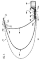
- FIG. 3 of the accompanying drawings there are shown in section another technique known for assemble the air intake lip 5, the frame front reinforcement 6 and the acoustic panel 7.
- the rear part 5a of the air intake lip 5 and the front part 7a of the acoustic panel 7 are arranged end to end, in line with one of the other.
- Each of these two parts is then fixed by rivets (illustrated respectively by lines 8 and 9) on a rear part 6a of the frame front reinforcement 6, placed inside parts 5a and 7a of the lip 5 and of the panel 7.
- the disassembly of the air intake lip 5, carried out by removing rivets 8, does not remove the bond provided by the rivets 9 between the acoustic panel 7 and the front frame 6.
- this technique has the disadvantage to leave uncovered the front end and the edge front of the acoustic panel 7, in the channel blower 3. This front end of the panel 7, as well than its front edge, are therefore exposed to all erosion, delamination, water insertion phenomena, etc. Since the acoustic panel 7 is usually made of composite material, this results in an acceleration that is hardly acceptable damage to this panel.
- the subject of the invention is precisely a air intake structure in which the connection between the air intake lip, the front reinforcement frame and the acoustic panel is made in such a way that the disadvantages of existing technologies are deleted; in particular, disassembly of the lip does not does not disappear the connection between the frame and the panel and the front end and the front edge of this panel are not exposed to air flow in the fan channel.
- the front part of the acoustic panel is placed in the extension of a rear part internal reinforcement frame and rear part internal of the air intake lip is fixed on the one hand to the internal rear part of the reinforcement frame and on the other hand to the front part of the acoustic panel by the second fixing means.
- the first fixing means advantageously comprise a plurality of pieces of bond, circumferentially distributed around a longitudinal axis of the motor and overlapping the part internal rear of the front reinforcement frame and the part front of the acoustic panel inside the structure.
- the first fixing means include also fasteners, such as rivets, linking the connecting parts on the one hand to the part internal rear of the front reinforcement frame and other part at the front of the acoustic panel.
- shims also through which the fasteners pass, can be interposed between the connecting parts and the part internal rear of the front reinforcement frame.
- the second means of fixation then include other organs of fixation, binding the internal rear part of the lip air inlet on the one hand, at the internal rear part of the front reinforcement frame and, on the other hand, to the part front of the acoustic panel, in locations offset from the connecting pieces.
- the front part of the acoustic panel is offset towards the inside of the structure, compared to the internal rear part of the front reinforcement frame.
- the first fixing means such as rivets, then include at least one connecting piece as well that fasteners connecting this part of a part in the internal rear part of the reinforcement frame front and on the other hand at the front of the panel acoustic, inside the structure.
- the front part of the acoustic panel can be substantially parallel to the internal rear part of the front reinforcement frame.
- the first ways to fixing then include two connecting pieces in shape of rectangular circular angles, two of which adjoining wings, oriented substantially radially relative to the longitudinal axis of the engine, are fixed to each other and whose other wings are attached respectively to the inner rear part of the frame front reinforcement and at the front of the panel acoustic by the aforementioned fixing members.
- the adjoining wings of the two connecting pieces can both be oriented towards the inside of the structure. Alternatively, they can also be oriented towards the inside of the structure for the part fixed to the internal rear part of the frame reinforcement before and out of the structure to the part fixed to the front part of the acoustic panel.
- the front part of the acoustic panel can also be oriented obliquely so as to end at near the rear edge of the front reinforcement frame.
- the first fixing means then comprise a single connecting piece in the form of a circular angle open, fixed on the one hand to the internal rear part of the front reinforcement frame and on the other hand to the part front of the acoustic panel by the connecting members.
- the second fixing means advantageously include other organs of fastening, such as rivets, binding the rear part internal air intake lip at the rear internal of the front reinforcement frame, crossing the connecting piece.
- FIGS 4 and 5 illustrate a first mode production of an air intake structure 14, for aircraft engine according to the invention.
- this structure 14 includes a lip air inlet 15, a front reinforcement frame 16 and a acoustic panel 17.
- the air intake lip 15 has a section U-shaped open backwards and shaped the outer casing of the front part of the nacelle of the motor.
- the front reinforcement frame 16 is mounted at the inside and back of the lip 15 and has also approximately a U-shaped section open to the rear. Its functions are to ensure the rigidity and maintenance of the shapes and dimensions of the front part of the nacelle.
- the acoustic panel 17 forms the outer shell of the nacelle, on the canal side fan 13 of the engine, at the rear of the lip air inlet 15. It is made of a material composite sandwich including a honeycomb core and inner and outer skins. In the game front 17a of panel 17, devoid of nest core bees, these skins are connected to each other.
- a external rear part 16b of the front reinforcement frame 16 is fixed inside a front part 20b of a outer casing 20, for example by means of rivets symbolized by the dashed lines 21. Furthermore, a external rear part 15b of the air intake lip 15 is fixed to the external rear part 16b, in the extension of part 20b, for example by means of rivets symbolized by the dashed lines 28.
- an internal rear part 16a of the front reinforcement frame 16 is fixed to the part front 17a of the acoustic panel 17 by first fastening means 19 which may take different forms, as we will see later.
- first fastening means 19 which may take different forms, as we will see later.
- the internal rear part 15a of the lip 15 is fixed to the less on the internal rear part 16a of the frame 16 by second fastening means 18 independent of first fastening means 19 and which will be described later.
- the internal rear part 15a of the lip air inlet 15 covers both the rear part 16a of the frame 16, the front part 17a of the panel 17 as well as the first fixing means 19.
- the removal of second fastening means 18 and rivets 23 allows disassemble the air intake lip 15 without the connection between frame 16 and panel 17, provided by the first fastening means 19, is deleted.
- the frame 16 and panel 17 thus form an assembly which remains rigid, after dismantling the second means of fixing 18.
- the arrangement is such that the front part 17a of the acoustic panel 17 is completely covered by the rear part 15a of the air intake lip 15. Any risk of damage accelerated acoustic panel 17 is thus avoided.
- the front part 17a of the panel acoustic 17 is placed in the extension of the internal rear part 16a of the front reinforcement frame 16.
- the first fixing means 19 comprise a plurality of connecting pieces 22, as well as fasteners, such as rivets 24, connecting parts 22 on the one hand to the part internal rear 16a of the frame 16 and on the other hand to the front part 17a of panel 17.
- parts 22 are parts approximately in H-shaped, regularly distributed over the entire circumference of the structure, around the axis longitudinal of the engine. More specifically, the pieces 22 overlap parts 16a and 17a towards the inside of the air intake structure, so that the central branch of the H is arranged along the line of junction between these two parts. Each piece 22 is then fixed by two rivets 24 to the rear part internal 16a of the frame 16 and, by two other rivets 24 to the front part 17a of the acoustic panel 17.
- the front part 17a of the acoustic panel 17 is generally more thicker than the inner rear portion 16a of the frame reinforcement before 16, preferably interposed between the part 16a and each of the parts 22 a wedge 26 thick (Figure 4).
- the rivets 24 pass through the pieces 22 as well as the part 16a or part 17a. More specifically, the 24 rivets include countersunk heads, housed in parts recessed machined in parts 16a and 17a, towards outside the structure. This arrangement allows fully house the rivet heads in the recesses. In other words, the heads of the rivets are flush with the surfaces of the turned parts 16a and 17a towards the outside of the structure.
- the internal rear part 15a of the lip 15 covers the parts 16a and 17a as well as the heads of the rivets 24.
- the second means of fixing by which this part 15a is fixed to the parts 16a and 17a are then formed by fasteners such as rivets 18 (illustrated by dashed lines in Figure 4). Some of these rivets 18 are used to fix the lip 15 on the frame 16 crossing parts 15a and 16a of these two parts at locations offset from the parts 22, as illustrated in particular in Figure 5. Other rivets 18 cross the part 15a of the lip 15 as well as the part 17a of panel 17 also in locations offset from workpieces 22.
- This second embodiment of the invention differs essentially from the first by the fact that instead of being placed in the extension of the internal rear part 16a of the frame 16, the front part 17a of the acoustic panel 17 is shifted towards inside the structure with respect to this part 16a.
- the front part 17a of the acoustic panel 17 is oriented substantially parallel to the internal rear part 16a of the frame reinforcement before 16.
- the first fastening means 19 connecting the frame 16 to the panel 17 include two connecting pieces 30 and 32, presenting both in the shape of a circular angle rectangle.
- a first wing, cylindrical, the connecting piece 30 is fixed to the interior of the internal rear part 16a of the frame 16 by fasteners such as rivets 34 and a first wing, cylindrical, of the piece of link 32 is fixed inside the front part 17a of the panel 17 by fixing members such as rivets (shown schematically by mixed lines 36).
- the second wings of connecting pieces 30 and 32 all extend two radially inward of the structure and are fixed to each other by fasteners such as rivets (shown schematically by mixed lines 38).
- the second wing of the connecting piece 30 extends radially inward of the structure and the second wing of the connecting piece 32 extends radially outward from the structure.
- These two wings are also attached to each other by fasteners such as rivets (shown schematically by mixed lines 38).
- the front part 17a of the acoustic panel 17 is oriented obliquely, so that its edge front ends near the inner rear edge of the rear part 16a of the frame 16.
- the first means of fixing 19 which connect the frame 16 to the panel 17 include a single connecting piece 30 which has the shape of an open circular angle.
- a first wing, cylindrical, of this connecting piece is fixed inside the internal rear part 16a of the frame 16 by means of fixing members such as rivets 34 and the second wing of the workpiece link 30 is fixed inside the front part 17a of the panel 17 by means of fixing members such as rivets, (shown schematically by mixed lines 36).
- the second fastening means 18 comprise members fasteners such as rivets, which pass through the parts 15a and 16a. Depending on the case, these rivets 18 can also cross the corresponding wing of room 30 or be placed at window level (not shown) provided for this purpose in this wing.
- the heads of the rivets 34 are housed in machined recesses on the inside of part 16a, so as to be flush with this face, as in the first embodiment described previously.
- the internal rear part 15a of the air intake lip 15 also extends towards the rear so as to ensure continuity with the surface of the acoustic panel 17 facing the channel blower, while fully covering the front part 17a of panel 17, as well as the first fastening means 19.
- this arrangement makes it possible to preserve the integrity of the connection between frame 16 and the panel 17 when the lip 15 is removed, while ensuring the protection of the front part 17a of the panel 17 when the lip 15 is in place.
- This layout also avoids any risk of accidental dismantling of the connection between frame 16 and the panel 17 during the removal of the lip 15, the fact that the first fastening means 19 connecting the frame and panel are completely covered by the internal rear part 15a of the lip 15.
- the invention is not limited to embodiments which have just been described in title of examples. So the forms given to the frame of front reinforcement 16, at the front part 17a of the panel acoustic 17 and the parts used to connect these two structural elements can undergo different modifications without departing from the scope of the invention.
- the parts 22 can be fixed on the frame 16 in a location shifted forward and toward inside the air intake structure.
- the lip air inlet may include a rear portion internal divided into two sections surrounding respectively the internal rear part of the frame 16 and the front part of the panel 17, and fixed thereto.
Applications Claiming Priority (2)
| Application Number | Priority Date | Filing Date | Title |
|---|---|---|---|
| FR9816123A FR2787509B1 (fr) | 1998-12-21 | 1998-12-21 | Structure d'entree d'air pour moteur d'aeronef |
| FR9816123 | 1998-12-21 |
Publications (2)
| Publication Number | Publication Date |
|---|---|
| EP1013910A1 true EP1013910A1 (de) | 2000-06-28 |
| EP1013910B1 EP1013910B1 (de) | 2005-05-25 |
Family
ID=9534229
Family Applications (1)
| Application Number | Title | Priority Date | Filing Date |
|---|---|---|---|
| EP99403184A Expired - Lifetime EP1013910B1 (de) | 1998-12-21 | 1999-12-17 | Struktur einer Flugzeugtriebwerksgondel |
Country Status (6)
| Country | Link |
|---|---|
| US (1) | US6328258B1 (de) |
| EP (1) | EP1013910B1 (de) |
| CA (1) | CA2292914C (de) |
| DE (1) | DE69925448T2 (de) |
| ES (1) | ES2244163T3 (de) |
| FR (1) | FR2787509B1 (de) |
Cited By (14)
| Publication number | Priority date | Publication date | Assignee | Title |
|---|---|---|---|---|
| WO2011027072A1 (fr) * | 2009-09-04 | 2011-03-10 | Aircelle | Ensemble structurant pour une tuyère d'éjection |
| FR2954282A1 (fr) * | 2009-12-22 | 2011-06-24 | Airbus Operations Sas | Nacelle incorporant un element de jonction entre une levre et un panneau d'attenuation acoustique |
| FR2954281A1 (fr) * | 2009-12-22 | 2011-06-24 | Airbus Operations Sas | Panneau pour le traitement acoustique a epaisseur evolutive |
| CN102124197A (zh) * | 2008-08-13 | 2011-07-13 | 斯奈克玛 | 涡轮机机舱的内壁 |
| FR2960856A1 (fr) * | 2010-06-07 | 2011-12-09 | Airbus Operations Sas | Cadre arriere d'une nacelle d'aeronef |
| WO2012104560A1 (fr) * | 2011-02-04 | 2012-08-09 | Aircelle | Procédé de fabrication d'une structure d'entrée d'air de nacelle de turboréacteur |
| FR2978988A1 (fr) * | 2011-08-12 | 2013-02-15 | Aircelle Sa | Cone d'ejection pour turboreacteur d'aeronef |
| FR3031360A1 (fr) * | 2015-01-07 | 2016-07-08 | Aircelle Sa | Ensemble propulsif pour aeronef |
| EP3309075A1 (de) * | 2016-10-13 | 2018-04-18 | Airbus Operations | Luftfahrzeuggondel, die eine verbindung zwischen einem lufteinlass und einer motorisierung umfasst |
| FR3060650A1 (fr) * | 2016-12-20 | 2018-06-22 | Airbus Operations | Structure d'entree d'air pour une nacelle d'aeronef |
| EP3361071A1 (de) * | 2017-02-10 | 2018-08-15 | Airbus Operations S.A.S. | Lufteinlassstruktur für luftfahrzeuggondel |
| EP3640452A1 (de) * | 2018-10-18 | 2020-04-22 | Airbus Operations | Frontteil der antriebsgruppengondel eines luftfahrzeugs, der einen hauptweg zur ausbreitung von kräften zwischen einer lufteinlasslippe und einer rückwärtigen membran eines schalldämmpaneels umfasst |
| WO2020109482A1 (de) * | 2018-11-28 | 2020-06-04 | Lufthansa Technik Ag | Verfahren und vorrichtung zur passgenauen herstellung von austauschstrukturteilen |
| US11325717B2 (en) | 2016-10-13 | 2022-05-10 | Airbus Operations Sas | Aircraft nacelle including a link between a conduit of an air inlet and a conduit of an engine |
Families Citing this family (50)
| Publication number | Priority date | Publication date | Assignee | Title |
|---|---|---|---|---|
| FR2812911B1 (fr) * | 2000-08-11 | 2002-09-20 | Aircelle Sa | Entree d'air pour nacelle de grandes dimensions a transportabilite amelioree |
| FR2837409B1 (fr) * | 2002-03-20 | 2004-06-04 | Airbus France | Procede de formage d'un secteur de levre d'entree d'air, dispositif pour sa mise en oeuvre et secteur ainsi obtenu |
| FR2840647B1 (fr) * | 2002-06-05 | 2004-10-29 | Airbus France | Dispositif pour le raccordement de deux pieces tubulaires de turboreacteur d'aeronef |
| FR2868123B1 (fr) * | 2004-03-29 | 2006-06-23 | Airbus France Sas | Structure d'entree d'air pour moteur d'aeronef |
| FR2868124B1 (fr) * | 2004-03-29 | 2006-06-23 | Airbus France Sas | Structure d'entree d'air pour moteur d'aeronef |
| US7513458B2 (en) * | 2005-04-22 | 2009-04-07 | Rohr, Inc. | Aircraft engine nacelle inlet having electrical ice protection system |
| US7469862B2 (en) * | 2005-04-22 | 2008-12-30 | Goodrich Corporation | Aircraft engine nacelle inlet having access opening for electrical ice protection system |
| WO2008048705A2 (en) | 2006-03-10 | 2008-04-24 | Goodrich Corporation | Low density lightning strike protection for use in airplanes |
| FR2898869B1 (fr) * | 2006-03-24 | 2008-12-12 | Aircelle Sa | Levre d'entree d'air de nacelle a degivrage electrique |
| EP2022886B1 (de) | 2006-05-02 | 2013-10-16 | Goodrich Corporation | Verfahren zur Herstellung nanoverstärkter Kohlenstofffasern sowie nanoverstärkte Kohlenstofffasern enthaltende Flugzeugkomponenten |
| FR2903733B1 (fr) * | 2006-07-12 | 2011-03-04 | Airbus France | Turbomoteur pour aeronef. |
| US7721525B2 (en) * | 2006-07-19 | 2010-05-25 | Rohr, Inc. | Aircraft engine inlet having zone of deformation |
| US20080166563A1 (en) | 2007-01-04 | 2008-07-10 | Goodrich Corporation | Electrothermal heater made from thermally conducting electrically insulating polymer material |
| US8206102B2 (en) | 2007-08-16 | 2012-06-26 | United Technologies Corporation | Attachment interface for a gas turbine engine composite duct structure |
| US8016237B2 (en) * | 2007-12-12 | 2011-09-13 | The Boeing Company | Methods and apparatus for an integrated aerodynamic panel |
| FR2929991B1 (fr) * | 2008-04-10 | 2010-05-07 | Airbus France | Panneau pour le traitement acoustique integrant un renfort de liaison |
| ITMI20080886A1 (it) * | 2008-05-15 | 2009-11-16 | Alenia Aermacchi Spa | Giunto per indurre elevate cadute di temperatura tra parti collegate su un velivolo |
| US8769924B2 (en) * | 2008-05-30 | 2014-07-08 | United Technologies Corporation | Gas turbine engine assembly including accessory components within the nacelle |
| FR2932106B1 (fr) * | 2008-06-06 | 2010-05-21 | Airbus France | Procede de depose d'un revetement visant a ameliorer l'ecoulement laminaire |
| US8757540B2 (en) * | 2008-06-30 | 2014-06-24 | Pratt & Whitney Canada Corp. | Nacelle inlet lip |
| FR2936223B1 (fr) * | 2008-09-23 | 2010-09-17 | Airbus France | Dispositif de liaison entre une entree d'air et une motorisation d'une nacelle d'aeronef |
| FR2938238B1 (fr) * | 2008-11-13 | 2010-11-12 | Aircelle Sa | Structure d'entree d'air de nacelle |
| FR2938236B1 (fr) * | 2008-11-13 | 2011-04-15 | Aircelle Sa | Nacelle pour turboreacteur |
| US7798285B2 (en) * | 2008-11-14 | 2010-09-21 | Rohr, Inc. | Acoustic barrel for aircraft engine nacelle including crack and delamination stoppers |
| EP2391542B1 (de) * | 2009-02-02 | 2014-07-30 | Airbus Operations (S.A.S.) | Triebwerksverkleidung mit lärmschutzvorrichtung |
| DE102009013585B4 (de) * | 2009-03-17 | 2012-01-26 | Airbus Operations Gmbh | Rumpfzellenstruktur für ein Flugzeug in Hybridbauweise |
| FR2943624B1 (fr) * | 2009-03-27 | 2011-04-15 | Airbus France | Nacelle d'aeronef comportant une paroi exterieure renforcee |
| US8197191B2 (en) | 2009-04-14 | 2012-06-12 | Rohr, Inc. | Inlet section of an aircraft engine nacelle |
| US20100284791A1 (en) * | 2009-05-11 | 2010-11-11 | Robert Jesse Flores | Apparatuses, systems, and methods for preventing foreign objects from being ingested into a jet engine |
| US8561934B2 (en) | 2009-08-28 | 2013-10-22 | Teresa M. Kruckenberg | Lightning strike protection |
| FR2960216B1 (fr) * | 2010-05-19 | 2013-02-15 | Aircelle Sa | Element d'aerodynamisme pour une nacelle d'aeronef |
| FR2966128B1 (fr) * | 2010-10-15 | 2013-06-14 | Airbus Operations Sas | Nacelle d'aeronef incorporant une zone de jonction continue entre une paroi exterieure et un cadre avant et/ou un cadre arriere |
| US9016042B2 (en) | 2011-05-20 | 2015-04-28 | Rohr, Inc. | Reinforcement members for aircraft propulsion system components configured to address delamination of the inner fixed structure |
| FR2980902B1 (fr) * | 2011-10-04 | 2013-09-13 | Aircelle Sa | Panneau d'attenuation acoustique structural |
| FR2988778B1 (fr) * | 2012-03-29 | 2014-03-21 | Aircelle Sa | Structure d'entree d'air de nacelle de turboreacteur de type laminaire |
| US9534505B2 (en) * | 2012-07-23 | 2017-01-03 | United Technologies Corporation | Integrated nacelle inlet and metallic fan containment case |
| FR2998547B1 (fr) * | 2012-11-23 | 2016-01-29 | Airbus Operations Sas | Nacelle d'aeronef comprenant une liaison deformable entre une entree d'air et une motorisation |
| US9038889B2 (en) | 2013-03-13 | 2015-05-26 | Bank Of America Corporation | Smart deposit |
| US9663238B2 (en) * | 2013-11-11 | 2017-05-30 | The Boeing Company | Nacelle inlet lip skin with pad-up defining a developable surface having parallel ruling lines |
| US9664113B2 (en) | 2014-03-15 | 2017-05-30 | The Boeing Company | One piece inlet lip skin design |
| US9764849B2 (en) * | 2014-09-18 | 2017-09-19 | The Boeing Company | Method of attaching nacelle structure to minimize fatigue loading |
| US9725190B2 (en) * | 2015-02-13 | 2017-08-08 | The Boeing Company | Aircraft engine inlet assembly apparatus |
| GB201809822D0 (en) * | 2018-06-15 | 2018-08-01 | Rolls Royce Plc | Gas turbine engine |
| FR3092871B1 (fr) * | 2019-02-15 | 2022-02-25 | Airbus Operations Sas | Procede d’assemblage d’une entree d’air d’un turboreacteur d’aeronef |
| US11280222B2 (en) | 2019-02-26 | 2022-03-22 | The Boeing Company | Bulkhead shims for curvilinear components |
| FR3095419B1 (fr) * | 2019-04-26 | 2021-10-01 | Safran Nacelles | Entrée d’air de nacelle à panneau acoustique |
| FR3095420B1 (fr) * | 2019-04-26 | 2023-04-21 | Safran Nacelles | Entrée d’air de nacelle et nacelle comportant une telle entrée d’air |
| FR3096657B1 (fr) * | 2019-05-27 | 2021-04-30 | Safran Nacelles | Lèvre d’entrée d’air de nacelle d’aéronef comportant au moins une source d’émission d’infrarouges |
| FR3099913A1 (fr) * | 2019-08-13 | 2021-02-19 | Airbus Operations | Partie antérieure de nacelle d’un ensemble propulsif d’aéronef dont le cadre avant est lié à une paroi extérieure sans la traverser |
| FR3134220A1 (fr) * | 2022-04-01 | 2023-10-06 | Airbus Operations (S.A.S.) | Panneau acoustique comprenant au moins deux structures alvéolaires imbriquées l’une dans l’autre, aéronef comportant au moins un tel panneau acoustique |
Citations (2)
| Publication number | Priority date | Publication date | Assignee | Title |
|---|---|---|---|---|
| US4759513A (en) * | 1986-09-26 | 1988-07-26 | Quiet Nacelle Corporation | Noise reduction nacelle |
| DE4340951A1 (de) * | 1992-12-04 | 1994-06-09 | Grumman Aerospace Corp | Einstückiges Triebwerkeinlaß-Schallrohr |
Family Cites Families (3)
| Publication number | Priority date | Publication date | Assignee | Title |
|---|---|---|---|---|
| US4749150A (en) * | 1985-12-24 | 1988-06-07 | Rohr Industries, Inc. | Turbofan duct with noise suppression and boundary layer control |
| USH648H (en) * | 1988-08-12 | 1989-07-04 | The United States Of America As Represented By The Secretary Of The Air Force | Air passage device |
| GB9424495D0 (en) * | 1994-12-05 | 1995-01-25 | Short Brothers Plc | Aerodynamic low drag structure |
-
1998
- 1998-12-21 FR FR9816123A patent/FR2787509B1/fr not_active Expired - Lifetime
-
1999
- 1999-12-14 US US09/461,177 patent/US6328258B1/en not_active Expired - Lifetime
- 1999-12-17 CA CA002292914A patent/CA2292914C/fr not_active Expired - Lifetime
- 1999-12-17 EP EP99403184A patent/EP1013910B1/de not_active Expired - Lifetime
- 1999-12-17 ES ES99403184T patent/ES2244163T3/es not_active Expired - Lifetime
- 1999-12-17 DE DE69925448T patent/DE69925448T2/de not_active Expired - Lifetime
Patent Citations (2)
| Publication number | Priority date | Publication date | Assignee | Title |
|---|---|---|---|---|
| US4759513A (en) * | 1986-09-26 | 1988-07-26 | Quiet Nacelle Corporation | Noise reduction nacelle |
| DE4340951A1 (de) * | 1992-12-04 | 1994-06-09 | Grumman Aerospace Corp | Einstückiges Triebwerkeinlaß-Schallrohr |
Cited By (30)
| Publication number | Priority date | Publication date | Assignee | Title |
|---|---|---|---|---|
| CN102124197A (zh) * | 2008-08-13 | 2011-07-13 | 斯奈克玛 | 涡轮机机舱的内壁 |
| CN102124197B (zh) * | 2008-08-13 | 2014-04-16 | 斯奈克玛 | 涡轮机机舱的内壁 |
| FR2949820A1 (fr) * | 2009-09-04 | 2011-03-11 | Aircelle Sa | Ensemble structurant pour une tuyere d'ejection. |
| WO2011027072A1 (fr) * | 2009-09-04 | 2011-03-10 | Aircelle | Ensemble structurant pour une tuyère d'éjection |
| CN102483012A (zh) * | 2009-09-04 | 2012-05-30 | 埃尔塞乐公司 | 排气喷嘴的结构化组件 |
| CN102483012B (zh) * | 2009-09-04 | 2015-07-15 | 埃尔塞乐公司 | 排气喷嘴的结构化组件 |
| US8505679B2 (en) | 2009-12-22 | 2013-08-13 | Airbus Operations Sas | Panel for the acoustic treatment with a progressive thickness |
| FR2954282A1 (fr) * | 2009-12-22 | 2011-06-24 | Airbus Operations Sas | Nacelle incorporant un element de jonction entre une levre et un panneau d'attenuation acoustique |
| FR2954281A1 (fr) * | 2009-12-22 | 2011-06-24 | Airbus Operations Sas | Panneau pour le traitement acoustique a epaisseur evolutive |
| WO2011086281A1 (fr) * | 2009-12-22 | 2011-07-21 | Airbus Operations Sas | Nacelle incorporant un element de jonction entre une levre et un panneau d'attenuation acoustique |
| WO2011086273A1 (fr) * | 2009-12-22 | 2011-07-21 | Airbus Operations Sas | Panneau pour le traitement acoustique a epaisseur evolutive |
| US9352844B2 (en) | 2009-12-22 | 2016-05-31 | Airbus Operations Sas | Nacelle incorporating an element for connecting a lip and an acoustic attenuation panel together |
| FR2960856A1 (fr) * | 2010-06-07 | 2011-12-09 | Airbus Operations Sas | Cadre arriere d'une nacelle d'aeronef |
| FR2971232A1 (fr) * | 2011-02-04 | 2012-08-10 | Aircelle Sa | Procede de fabrication d'une structure d'entree d'air de nacelle de turboreacteur |
| WO2012104560A1 (fr) * | 2011-02-04 | 2012-08-09 | Aircelle | Procédé de fabrication d'une structure d'entrée d'air de nacelle de turboréacteur |
| US9481054B2 (en) | 2011-02-04 | 2016-11-01 | Aircelle | Method for manufacturing an air intake structure for a turbojet engine nacelle |
| FR2978988A1 (fr) * | 2011-08-12 | 2013-02-15 | Aircelle Sa | Cone d'ejection pour turboreacteur d'aeronef |
| WO2013024216A1 (fr) * | 2011-08-12 | 2013-02-21 | Aircelle | Cône d'éjection pour turboréacteur d'aéronef |
| FR3031360A1 (fr) * | 2015-01-07 | 2016-07-08 | Aircelle Sa | Ensemble propulsif pour aeronef |
| US11325717B2 (en) | 2016-10-13 | 2022-05-10 | Airbus Operations Sas | Aircraft nacelle including a link between a conduit of an air inlet and a conduit of an engine |
| EP3309075A1 (de) * | 2016-10-13 | 2018-04-18 | Airbus Operations | Luftfahrzeuggondel, die eine verbindung zwischen einem lufteinlass und einer motorisierung umfasst |
| FR3057544A1 (fr) * | 2016-10-13 | 2018-04-20 | Airbus Operations | Nacelle d'aeronef comprenant une liaison entre une entree d'air et une motorisation |
| FR3060650A1 (fr) * | 2016-12-20 | 2018-06-22 | Airbus Operations | Structure d'entree d'air pour une nacelle d'aeronef |
| US10676203B2 (en) | 2016-12-20 | 2020-06-09 | Airbus Operations S.A.S. | Air input structure for an aircraft nacelle |
| FR3062880A1 (fr) * | 2017-02-10 | 2018-08-17 | Airbus | Structure d'entree d'air pour une nacelle d'aeronef |
| EP3361071A1 (de) * | 2017-02-10 | 2018-08-15 | Airbus Operations S.A.S. | Lufteinlassstruktur für luftfahrzeuggondel |
| EP3640452A1 (de) * | 2018-10-18 | 2020-04-22 | Airbus Operations | Frontteil der antriebsgruppengondel eines luftfahrzeugs, der einen hauptweg zur ausbreitung von kräften zwischen einer lufteinlasslippe und einer rückwärtigen membran eines schalldämmpaneels umfasst |
| FR3087489A1 (fr) * | 2018-10-18 | 2020-04-24 | Airbus Operations | Partie anterieure de nacelle de groupe propulsif d'aeronef comportant une voie principale de propagation d'efforts entre une levre d'entree d'air et une peau arriere d'un panneau acoustique |
| US11649062B2 (en) | 2018-10-18 | 2023-05-16 | Airbus Operations Sas | Forward part of an aircraft propulsion unit nacelle comprising a main propagation path for forces between an air intake lip and a back skin of an acoustic panel |
| WO2020109482A1 (de) * | 2018-11-28 | 2020-06-04 | Lufthansa Technik Ag | Verfahren und vorrichtung zur passgenauen herstellung von austauschstrukturteilen |
Also Published As
| Publication number | Publication date |
|---|---|
| FR2787509A1 (fr) | 2000-06-23 |
| DE69925448T2 (de) | 2006-02-02 |
| FR2787509B1 (fr) | 2001-03-30 |
| ES2244163T3 (es) | 2005-12-01 |
| US6328258B1 (en) | 2001-12-11 |
| CA2292914C (fr) | 2007-09-25 |
| EP1013910B1 (de) | 2005-05-25 |
| DE69925448D1 (de) | 2005-06-30 |
| CA2292914A1 (fr) | 2000-06-21 |
Similar Documents
| Publication | Publication Date | Title |
|---|---|---|
| CA2292914C (fr) | Structure d'entree d'air pour moteur d'aeronef | |
| EP1369555B1 (de) | Einrichtung um zwei rohrförmige Teile eines Strahltriebwerks zu verbinden | |
| EP0898063B1 (de) | Geräuschdämpfungseinrichtung für ein Mantelstromtriebwerk | |
| EP2072397B1 (de) | Verlängerung des Zwischengehäuses für ein Flugzeugturbinentriebwerk, die eine in Sektoren unterteilte Ringnut zur Aufnahme der Triebwerksverkleidung umfasst | |
| EP2038176B1 (de) | Motoranordnung für ein luftfahrzeug mit an zwei getrennten elementen angebrachter aerodynamischer kupplungsverteilung | |
| EP0960051B1 (de) | Flugzeug-triebwerksanlage mit sicherheitseinrichtungen für das stellen und festhalten von den gebläsehauben | |
| EP0017546B1 (de) | Auswechselbarer Träger für die Anstreif-Dichtungsschicht im Gehäuse eines Bläsertriebwerkes | |
| EP2986507A1 (de) | Gondel für flugzeugturbostrahltriebwerk mit verlängerter frontlippe | |
| WO2009103905A1 (fr) | Nacelle pour moteur d'aéronef à tuyère de section variable | |
| EP0601910B1 (de) | Schubumkehrklappe mit Deflektoren zur Strahlbeeinflussung | |
| WO2014096647A1 (fr) | Extension de carter intermediaire a conception amelioree | |
| WO2009138580A1 (fr) | Ensemble propulsif pour aéronef, et structure d'entrée d'air pour un tel ensemble | |
| EP3594126A1 (de) | Lufteinlass, gondel und antriebseinheit eines luftfahrzeugs mit monoblocksektoren | |
| WO1996038661A1 (fr) | Ensemble d'inverseur de poussee a deux portes | |
| FR3020347A1 (fr) | Procede d'assemblage d'une partie arriere d'aeronef | |
| EP3548380B1 (de) | Flugzeugstriebwerksgondel, antriebsanordnung und flugzeug beinhaltend solche gondel | |
| WO2011138571A1 (fr) | Ensemble pour système propulsif d'aéronef | |
| FR2938824A1 (fr) | Nacelle integree sur aile volante | |
| EP3361071B1 (de) | Lufteinlassstruktur für luftfahrzeuggondel | |
| CA2705361A1 (fr) | Inverseur de poussee a portes pour turboreacteur | |
| WO2016092238A1 (fr) | Procédé pour la réparation d'un panneau acoustique en matériau composite | |
| WO2018002560A1 (fr) | Agencement pour la fixation d'une bielle de volet d'inversion de poussée sur une structure interne fixe d'une nacelle de turboréacteur et procédé de montage/démontage associé | |
| FR3008021A1 (fr) | Procede de reparation d'un panneau par application d'un doubleur | |
| EP3778381B1 (de) | Frontteil einer gondel einer antriebsgruppe eines luftfahrzeugs, dessen lufteinlasslippe mit einem externen paneel über ein verbundsystem verbunden ist | |
| FR3040044A1 (fr) | Capot de nacelle comportant un element de maintien en position solidarise a la paroi interne du capot |
Legal Events
| Date | Code | Title | Description |
|---|---|---|---|
| PUAI | Public reference made under article 153(3) epc to a published international application that has entered the european phase |
Free format text: ORIGINAL CODE: 0009012 |
|
| AK | Designated contracting states |
Kind code of ref document: A1 Designated state(s): DE ES GB IT NL |
|
| AX | Request for extension of the european patent |
Free format text: AL;LT;LV;MK;RO;SI |
|
| 17P | Request for examination filed |
Effective date: 20001130 |
|
| AKX | Designation fees paid |
Free format text: DE ES GB IT NL |
|
| RAP1 | Party data changed (applicant data changed or rights of an application transferred) |
Owner name: EUROPEAN AERONAUTIC DEFENCE AND SPACE COMPANY - EA |
|
| RAP1 | Party data changed (applicant data changed or rights of an application transferred) |
Owner name: AIRBUS FRANCE |
|
| 17Q | First examination report despatched |
Effective date: 20031217 |
|
| GRAP | Despatch of communication of intention to grant a patent |
Free format text: ORIGINAL CODE: EPIDOSNIGR1 |
|
| GRAS | Grant fee paid |
Free format text: ORIGINAL CODE: EPIDOSNIGR3 |
|
| GRAA | (expected) grant |
Free format text: ORIGINAL CODE: 0009210 |
|
| AK | Designated contracting states |
Kind code of ref document: B1 Designated state(s): DE ES GB IT NL |
|
| REG | Reference to a national code |
Ref country code: GB Ref legal event code: FG4D Free format text: NOT ENGLISH |
|
| REF | Corresponds to: |
Ref document number: 69925448 Country of ref document: DE Date of ref document: 20050630 Kind code of ref document: P |
|
| GBT | Gb: translation of ep patent filed (gb section 77(6)(a)/1977) |
Effective date: 20050831 |
|
| REG | Reference to a national code |
Ref country code: ES Ref legal event code: FG2A Ref document number: 2244163 Country of ref document: ES Kind code of ref document: T3 |
|
| PLBE | No opposition filed within time limit |
Free format text: ORIGINAL CODE: 0009261 |
|
| STAA | Information on the status of an ep patent application or granted ep patent |
Free format text: STATUS: NO OPPOSITION FILED WITHIN TIME LIMIT |
|
| 26N | No opposition filed |
Effective date: 20060228 |
|
| PGFP | Annual fee paid to national office [announced via postgrant information from national office to epo] |
Ref country code: NL Payment date: 20091222 Year of fee payment: 11 |
|
| PGFP | Annual fee paid to national office [announced via postgrant information from national office to epo] |
Ref country code: DE Payment date: 20101222 Year of fee payment: 12 Ref country code: IT Payment date: 20101228 Year of fee payment: 12 |
|
| PGFP | Annual fee paid to national office [announced via postgrant information from national office to epo] |
Ref country code: ES Payment date: 20101223 Year of fee payment: 12 |
|
| REG | Reference to a national code |
Ref country code: NL Ref legal event code: V1 Effective date: 20110701 |
|
| REG | Reference to a national code |
Ref country code: GB Ref legal event code: 732E Free format text: REGISTERED BETWEEN 20110721 AND 20110727 |
|
| PG25 | Lapsed in a contracting state [announced via postgrant information from national office to epo] |
Ref country code: NL Free format text: LAPSE BECAUSE OF NON-PAYMENT OF DUE FEES Effective date: 20110701 |
|
| REG | Reference to a national code |
Ref country code: ES Ref legal event code: PC2A Owner name: AIRBUS OPERATIONS SAS Effective date: 20120308 |
|
| REG | Reference to a national code |
Ref country code: DE Ref legal event code: R082 Ref document number: 69925448 Country of ref document: DE Representative=s name: PATENT- UND RECHTSANWAELTE KRAUS & WEISERT, DE |
|
| REG | Reference to a national code |
Ref country code: DE Ref legal event code: R082 Ref document number: 69925448 Country of ref document: DE Representative=s name: KRAUS & WEISERT PATENTANWAELTE PARTGMBB, DE Effective date: 20120326 Ref country code: DE Ref legal event code: R082 Ref document number: 69925448 Country of ref document: DE Representative=s name: PATENT- UND RECHTSANWAELTE KRAUS & WEISERT, DE Effective date: 20120326 Ref country code: DE Ref legal event code: R081 Ref document number: 69925448 Country of ref document: DE Owner name: AIRBUS OPERATIONS SAS, FR Free format text: FORMER OWNER: AIRBUS FRANCE, TOULOUSE, FR Effective date: 20120326 |
|
| REG | Reference to a national code |
Ref country code: DE Ref legal event code: R119 Ref document number: 69925448 Country of ref document: DE Effective date: 20120703 |
|
| PG25 | Lapsed in a contracting state [announced via postgrant information from national office to epo] |
Ref country code: DE Free format text: LAPSE BECAUSE OF NON-PAYMENT OF DUE FEES Effective date: 20120703 |
|
| PG25 | Lapsed in a contracting state [announced via postgrant information from national office to epo] |
Ref country code: IT Free format text: LAPSE BECAUSE OF NON-PAYMENT OF DUE FEES Effective date: 20111217 |
|
| REG | Reference to a national code |
Ref country code: ES Ref legal event code: FD2A Effective date: 20131029 |
|
| PG25 | Lapsed in a contracting state [announced via postgrant information from national office to epo] |
Ref country code: ES Free format text: LAPSE BECAUSE OF NON-PAYMENT OF DUE FEES Effective date: 20111218 |
|
| PGFP | Annual fee paid to national office [announced via postgrant information from national office to epo] |
Ref country code: GB Payment date: 20181218 Year of fee payment: 20 |
|
| REG | Reference to a national code |
Ref country code: GB Ref legal event code: PE20 Expiry date: 20191216 |
|
| PG25 | Lapsed in a contracting state [announced via postgrant information from national office to epo] |
Ref country code: GB Free format text: LAPSE BECAUSE OF EXPIRATION OF PROTECTION Effective date: 20191216 |