EP0601910B1 - Schubumkehrklappe mit Deflektoren zur Strahlbeeinflussung - Google Patents
Schubumkehrklappe mit Deflektoren zur Strahlbeeinflussung Download PDFInfo
- Publication number
- EP0601910B1 EP0601910B1 EP93402875A EP93402875A EP0601910B1 EP 0601910 B1 EP0601910 B1 EP 0601910B1 EP 93402875 A EP93402875 A EP 93402875A EP 93402875 A EP93402875 A EP 93402875A EP 0601910 B1 EP0601910 B1 EP 0601910B1
- Authority
- EP
- European Patent Office
- Prior art keywords
- sole plate
- reverser
- door
- stiffener
- thrust reverser
- Prior art date
- Legal status (The legal status is an assumption and is not a legal conclusion. Google has not performed a legal analysis and makes no representation as to the accuracy of the status listed.)
- Expired - Lifetime
Links
Images


Classifications
-
- F—MECHANICAL ENGINEERING; LIGHTING; HEATING; WEAPONS; BLASTING
- F02—COMBUSTION ENGINES; HOT-GAS OR COMBUSTION-PRODUCT ENGINE PLANTS
- F02K—JET-PROPULSION PLANTS
- F02K1/00—Plants characterised by the form or arrangement of the jet pipe or nozzle; Jet pipes or nozzles peculiar thereto
- F02K1/54—Nozzles having means for reversing jet thrust
- F02K1/56—Reversing jet main flow
- F02K1/563—Reversing jet main flow in specified direction, e.g. to obviate its reinjection
-
- F—MECHANICAL ENGINEERING; LIGHTING; HEATING; WEAPONS; BLASTING
- F02—COMBUSTION ENGINES; HOT-GAS OR COMBUSTION-PRODUCT ENGINE PLANTS
- F02K—JET-PROPULSION PLANTS
- F02K1/00—Plants characterised by the form or arrangement of the jet pipe or nozzle; Jet pipes or nozzles peculiar thereto
- F02K1/54—Nozzles having means for reversing jet thrust
- F02K1/64—Reversing fan flow
- F02K1/70—Reversing fan flow using thrust reverser flaps or doors mounted on the fan housing
Definitions
- the present invention relates to a thrust reverser of the overhead door type intended to equip a jet engine.
- the doors are designed to move between two positions, namely a so-called “cruising” position in which they constitute cover elements for a gas ejection channel allowing circulation of the flow of upstream downstream gas, and a so-called “thrust reversal” position in which the doors, after tilting, at least partially close the ejection channel and deflect a gas flow radially outward and inward upstream.
- the invention proposes an improvement to known reverser doors in which, in order to assist in reversing and guiding the deflected flow, at least one deflector structure is provided which extends approximately perpendicularly to the door. from the internal face of the latter, deflecting structure situated at the upstream end of the door and / or on the lateral edges of the latter.
- the transverse stiffener and the sole are integral so as to constitute a non-deformable frame, the sole having at its two ends lateral members delimiting with the sole a U-shaped space where the blades are housed, the transverse stiffener being attached to the free ends of the side members.
- the deflecting vanes have an aerodynamic profile in the shape of a wing whose leading edge, preferably rounded, is oriented towards the inside of the door and the trailing edge is located in the same plane as the sole of the deflector structure.
- the blades are substantially parallel to each other and are inclined at an angle between 0 ° and 70 ° relative to the normal to the plane of the sole (angle of attack). Similarly, the geometric center of the end of each blade linked to the sole is offset from the geometric center of the end of the blade linked to the stiffener by an angle between 0 ° and 30 °.
- transverse stiffener will advantageously have a wing-shaped section with rounded leading edge oriented towards the inside of the door and trailing edge located in the same plane as the trailing edges of the blades.
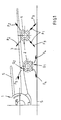
- FIG. 1 schematically represents, front view, the right part of a jet plane 1 of the type with engines 2 suspended under the wings 3 of the plane.
- the airplane rolls on the ground S and the door reversers 4 of the engines are in the deployed thrust reversal position.
- the direction of the reverse flow is indicated by the arrows F1 and F2.
- the arrows F1 show that the flow hits the ground, which is likely to cause stones to be thrown and especially hot air blows according to arrow F3 which can be re-ingested by the motors, with a risk of deterioration of these latter.
- the reverse flow along arrow F2 risks striking the horizontal tail 5 of the airplane, creating undesirable effects, in particular on the handling of the airplane.
- the inverted gas stream guidance system according to the invention which it is assumed that the left engine is equipped with, eliminates these drawbacks.
- the lower doors of the inverter equipped with the guide system G1 makes it possible to orient the reverse flow substantially according to the arrows F4 according to a trajectory which tangents the ground and spreads the flow laterally.
- the upper doors may be fitted with a similar guidance system G2 which will deflect the flow in an arrow F5 away from the horizontal tail 5.
- FIGS. 2 to 7 The ply guide system will now be described in more detail with reference to FIGS. 2 to 7. It is obvious that this system can be fitted to any type of inverter door to door and applies to fixed motors not only, such as in FIG. 1, under the wing, but also to engines arranged in any other place on the aircraft.
- the thrust reverser is constituted by several doors 4 articulated so as to tilt around an axis A under the action of a jack.
- control V between a so-called “cruising” position in which the door is aligned with the cover parts C and completely releases the annular channel CA and a so-called “inversion” position shown in solid line in FIG. 2 and in which the downstream part of the door closes the channel CA while its upstream part projects outside the cowling so as to deflect the flow Fx radially outwards and upstream.
- the door 4 has on its upstream edge 11 at least one front deflector structure, or spoiler, generally designated at D and extending from the internal face of the door.
- the invention relates to the particular construction of this deflecting structure which allows lateral guidance of the diverted flow.
- This deflecting structure in the embodiment shown, given by way of nonlimiting example, comprises a sole 10 fixed (by welding, riveting or bolting) against the edge 11 of the door. At its ends, the sole is extended upwards by two lateral members 12 and 13 (FIG. 3) which form with the sole 10 a U-shaped frame delimiting an empty space 14. The upper end of the members 12 and 13 is capped by a transverse stiffener 15.
- blades 16 shaped as a wing, the foot 17 of which is fixed to the sole 10 and the head 18 is fixed under the stiffener 15, the head 18 being longer than the foot 17.
- Figure 4 which is a top view of Figure 3, the blades 16 are substantially parallel to each other and are inclined at an angle a with respect to the normal N to the sole which can be between 0 ° and 70 ° according to the lateral orientation needs of the diverted flow.
- the rounded leading edge 19 of the vanes 16 is oriented towards the inside of the door, while their trailing edge 20 is turned towards the outside, the trailing edge which is situated in the same plane as the sole 10 and the members 12,13 of the deflector structure.
- the geometric center 21 of the root 17 of each blade is offset from the geometric center 22 of the blade head 18 by an angle b which can be between 0 ° and 30 °.
- the blades 16 have, seen from the front, a substantially trapezoidal shape, their trailing edge 20 being roughly perpendicular to the foot 17 and to the head 18 of the blade , while their leading edge 19 is inclined.
- the blade root 17 is shorter than the blade head 18.
- the stiffener 15 for its part, can advantageously also have an aerodynamic section in the shape of a wing with rounded leading edge 23 (FIG. 2) oriented towards the inside of the door and linear trailing edge 24 situated in the same plane. as the trailing edges of the blades 16.
- the angle c between the stiffener 15 and the plane of the U-shaped space 14 delimited by the frame 10, 11, 13 is between 30 ° and 90 °.
Claims (10)
- Schubumkehrvorrichtung für Strahltriebwerk mit schwenkbaren Klappen (4), die sich zwischen zwei Stellungen bewegen können, und zwar zwischen einer sogenannten Fahrtstellung, in der die Klappen (4) Verkleidungselemente (C) eines Gasausstoßkanals (CA) bilden, die eine Strömung des Gasstroms von vorne nach hinten gestatten, und einer sogenannten Schubumkehrstellung, in der die Klappen (4) nach Verschwenken den Ausstoßkanal (CA) mindestens teilweise verschließen und einen Gasstrom radial nach außen und nach vorne ablenken, wobei jede der Klappen (4) an ihrem vorderen Rand (11) eine Ablenkstruktur (D) aufweist, die sich ungefähr senkrecht zur Klappe (4) erstreckt und dazu bestimmt ist, den abgelenkten Strom zu führen, wobei diese Umkehrvorrichtung dadurch gekennzeichnet ist, daß die Ablenkstruktur (D) aus den folgenden Bauteilen besteht:- eine an dem Rand (11) der Klappe (4) befestigte Fußplatte (10),- eine von dieser Fußplatte (10) entfernte Querversteifung (15), die mit dieser einen leeren Raum (14) abgrenzt, und- eine Reihe von Ablenkschaufeln (16), die in diesem leeren Raum (14) zwischen der Fußplatte (10) und der Versteifung (15) untergebracht sind und an der Fußplatte und an der Versteifung befestigt sind.
- Umkehrvorrichtung nach Anspruch 1, dadurch gekennzeichnet, daß die Querversteifung (15) und die Fußplatte (10) miteinander fest verbunden sind, so daß sie einen unverformbaren Rahmen bilden.
- Umkehrvorrichtung nach Anspruch 1 oder 2, dadurch gekennzeichnet, daß die Fußplatte (10) an ihren beiden Enden seitliche Spanten (12, 13) aufweist, die mit der Fußplatte einen U-förmigen Raum (14) abgrenzen, in dem die Schaufeln (16) untergebracht sind.
- Umkehrvorrichtung nach Anspruch 3, dadurch gekennzeichnet, daß die Querversteifung (15) an den freien Enden der seitlichen Spanten (12, 13) befestigt ist.
- Umkehrvorrichtung nach einem der Ansprüche 1 bis 4, dadurch gekennzeichnet, daß die Ablenkschaufeln (16) ein aerodynamisches Profil in Form eines Flügels haben, dessen Eintrittskante (19) dem Inneren der Klappe (4) zugewandt ist und dessen Austrittskante (20) in derselben Ebene wie die Fußplatte (10) der Ablenkstruktur (D) liegt.
- Schubumkehrvorrichtung nach einem der Ansprüche 1 bis 5, dadurch gekennzeichnet, daß die Ablenkschaufeln (16) im wesentlichen zueinander parallel sind und gegen die Normale (N) auf die Ebene der Fußplatte um einen Winkel a von 0° bis 70° geneigt sind (Anstellwinkel).
- Schubumkehrvorrichtung nach einem der Ansprüche 1 bis 6, dadurch gekennzeichnet, daß der geometrische Mittelpunkt (21) des mit der Fußplatte (10) verbundenen Endes jeder Schaufel (16) gegen den geometrischen Mittelpunkt (22) des mit der Querversteifung (15) verbundenen Endes der Schaufel um einen Winkel b von 0° bis 30° versetzt ist.
- Schubumkehrvorrichtung nach einem der Ansprüche 1 bis 7, dadurch gekennzeichnet, daß die Querversteifung (15) einen flügelförmigen Querschnitt mit einer abgerundeten Eintrittskante (23), die dem Inneren der Klappe zugewandt ist, und mit einer Austrittskante (24) hat, die in derselben Ebene wie die Austrittskanten der Schaufeln gelegen ist.
- Schubumkehrvorrichtung nach einem der Ansprüche 1 bis 8, dadurch gekennzeichnet, daß das mit der Querversteifung (15) verbundene Ende (18) der Schaufel länger als das mit der Fußplatte verbundene Ende (17) ist.
- Schubumkehrvorrichtung nach einem der Ansprüche 3 bis 9, dadurch gekennzeichnet, daß die Querversteifung mit der Ebene des von der Fußplatte und ihren beiden seitlichen Spanten abgegrenzten U-förmigen Raums (14) einen Winkel c von 30° bis 90° bildet.
Applications Claiming Priority (2)
| Application Number | Priority Date | Filing Date | Title |
|---|---|---|---|
| FR9214615A FR2698913B1 (fr) | 1992-12-04 | 1992-12-04 | Ensemble d'inversion de poussée à portes équipé d'un dispositif de contrôle de jet. |
| FR9214615 | 1992-12-04 |
Publications (2)
| Publication Number | Publication Date |
|---|---|
| EP0601910A1 EP0601910A1 (de) | 1994-06-15 |
| EP0601910B1 true EP0601910B1 (de) | 1997-03-19 |
Family
ID=9436228
Family Applications (1)
| Application Number | Title | Priority Date | Filing Date |
|---|---|---|---|
| EP93402875A Expired - Lifetime EP0601910B1 (de) | 1992-12-04 | 1993-11-29 | Schubumkehrklappe mit Deflektoren zur Strahlbeeinflussung |
Country Status (4)
| Country | Link |
|---|---|
| US (1) | US5396762A (de) |
| EP (1) | EP0601910B1 (de) |
| DE (1) | DE69309007T2 (de) |
| FR (1) | FR2698913B1 (de) |
Families Citing this family (21)
| Publication number | Priority date | Publication date | Assignee | Title |
|---|---|---|---|---|
| FR2738291B1 (fr) * | 1995-09-06 | 1997-09-26 | Hispano Suiza Sa | Inverseur de poussee de turboreacteur a portes associees a un panneau amont formant ecope |
| DE69521806D1 (de) * | 1995-09-13 | 2001-08-23 | Hurel Dubois Avions | Strahlumkehrgitter für eine Schubumkehrvorrichtungsklappe |
| US5794433A (en) * | 1996-06-18 | 1998-08-18 | The Nordam Group, Inc. | Thrust reverser door side fillers |
| US5915651A (en) * | 1997-07-10 | 1999-06-29 | Mcdonnell Douglas Corporation | Reverse thrust inlet vortex inhibitor |
| FR2776023B1 (fr) * | 1998-03-12 | 2000-04-07 | Hispano Suiza Sa | Inverseur de poussee de turboreacteur a portes formant ecopes associees a une grille mobile |
| US6311928B1 (en) | 2000-01-05 | 2001-11-06 | Stage Iii Technologies, L.C. | Jet engine cascade thrust reverser for use with mixer/ejector noise suppressor |
| FR2887854B1 (fr) * | 2005-06-30 | 2008-08-08 | Airbus France Sas | Nacelle pour aeronef et aeronef muni d'au moins une telle nacelle |
| US8015797B2 (en) * | 2006-09-21 | 2011-09-13 | Jean-Pierre Lair | Thrust reverser nozzle for a turbofan gas turbine engine |
| US8091827B2 (en) | 2007-11-16 | 2012-01-10 | The Nordam Group, Inc. | Thrust reverser door |
| US8172175B2 (en) | 2007-11-16 | 2012-05-08 | The Nordam Group, Inc. | Pivoting door thrust reverser for a turbofan gas turbine engine |
| US8052085B2 (en) | 2007-11-16 | 2011-11-08 | The Nordam Group, Inc. | Thrust reverser for a turbofan gas turbine engine |
| US7735778B2 (en) * | 2007-11-16 | 2010-06-15 | Pratt & Whitney Canada Corp. | Pivoting fairings for a thrust reverser |
| US8051639B2 (en) * | 2007-11-16 | 2011-11-08 | The Nordam Group, Inc. | Thrust reverser |
| US8052086B2 (en) * | 2007-11-16 | 2011-11-08 | The Nordam Group, Inc. | Thrust reverser door |
| US8127530B2 (en) | 2008-06-19 | 2012-03-06 | The Nordam Group, Inc. | Thrust reverser for a turbofan gas turbine engine |
| FR2955154B1 (fr) * | 2010-01-08 | 2012-01-06 | Airbus Operations Sas | Inverseur de poussee pour aeronef a turboreacteurs a double flux semi-enterres |
| US9663239B2 (en) | 2012-11-12 | 2017-05-30 | United Technologies Corporation | Clocked thrust reversers |
| WO2014092757A1 (en) * | 2012-12-11 | 2014-06-19 | United Technologies Corporation | Asymmetric thrust reversers |
| FR3082889A1 (fr) * | 2018-06-26 | 2019-12-27 | Airbus Operations | Turboreacteur comportant une nacelle equipee de volets inverseurs pourvus de moyens pour generer des tourbillons |
| FR3092145A1 (fr) * | 2019-01-24 | 2020-07-31 | Airbus Operations | Turboreacteur double flux comportant une serie de lames rotatives pour obturer la veine du flux secondaire |
| FR3105986B1 (fr) * | 2020-01-02 | 2021-12-03 | Safran Nacelles | Inverseur de poussée à portes comprenant un déflecteur pour rediriger un flux d’air vers l’amont |
Family Cites Families (13)
| Publication number | Priority date | Publication date | Assignee | Title |
|---|---|---|---|---|
| US3097484A (en) * | 1960-06-13 | 1963-07-16 | Thrust reversers for jet engines | |
| US3303653A (en) * | 1965-06-30 | 1967-02-14 | Gen Electric | Lightweight thrust reverser |
| FR1529361A (fr) * | 1966-06-29 | 1968-06-14 | Rolls Royce | Dispositif inverseur de la poussée |
| US3500644A (en) * | 1968-04-10 | 1970-03-17 | Rohr Corp | Thrust reverser |
| FR2126922B1 (de) * | 1971-01-20 | 1975-01-17 | Snecma | |
| US4216923A (en) * | 1977-03-30 | 1980-08-12 | Boeing Commercial Airplane Company | Target type thrust reverser |
| GB2185719B (en) * | 1986-01-25 | 1989-11-01 | Rolls Royce | Fluid flow reversing apparatus |
| FR2618852B1 (fr) * | 1987-07-29 | 1989-11-10 | Hispano Suiza Sa | Inverseur de poussee de turboreacteur muni d'un dispositif redresseur de flux |
| FR2618853B1 (fr) * | 1987-07-29 | 1989-11-10 | Hispano Suiza Sa | Inverseur de poussee de turboreacteur muni d'un deflecteur mobile de porte |
| FR2651278B1 (fr) * | 1989-08-23 | 1994-05-06 | Hispano Suiza | Inverseur a grilles sans capot coulissant pour turboreacteur. |
| US5228641A (en) * | 1991-08-15 | 1993-07-20 | Rohr, Inc. | Cascade type aircraft engine thrust reverser with hidden link actuator |
| FR2681101B1 (fr) * | 1991-09-11 | 1993-11-26 | Hispano Suiza | Inverseur de poussee de turboreacteur a pilotage ameliore des nappes du flux inverse. |
| FR2687733B1 (fr) * | 1992-02-26 | 1995-08-04 | Hurel Dubois Avions | Inverseur de poussee pour moteur a reaction assurant un guidage du flux devie. |
-
1992
- 1992-12-04 FR FR9214615A patent/FR2698913B1/fr not_active Expired - Lifetime
-
1993
- 1993-11-29 EP EP93402875A patent/EP0601910B1/de not_active Expired - Lifetime
- 1993-11-29 DE DE69309007T patent/DE69309007T2/de not_active Expired - Lifetime
- 1993-12-01 US US08/160,424 patent/US5396762A/en not_active Expired - Lifetime
Also Published As
| Publication number | Publication date |
|---|---|
| DE69309007T2 (de) | 1997-10-16 |
| FR2698913A1 (fr) | 1994-06-10 |
| EP0601910A1 (de) | 1994-06-15 |
| US5396762A (en) | 1995-03-14 |
| DE69309007D1 (de) | 1997-04-24 |
| FR2698913B1 (fr) | 1995-02-03 |
Similar Documents
| Publication | Publication Date | Title |
|---|---|---|
| EP0601910B1 (de) | Schubumkehrklappe mit Deflektoren zur Strahlbeeinflussung | |
| CA2624005C (fr) | Ensemble moteur pour aeronef comprenant un moteur ainsi qu'un mat d'accrochage d'un tel moteur | |
| EP0822327B1 (de) | Schubumkehrvorrichtung für ein Bläsertriebwerk mit Umkehrklappen, die Kanäle formen | |
| EP0806563B1 (de) | Klappen mit Leitflächen für eine Schubumkehrvorrichtung eines Bläsertriebwerkes | |
| EP0777045B1 (de) | Schubumkehrvorrichtung mit Klappen und an dem Hinterteil verbundenen Hilfsklappen | |
| EP0828934B1 (de) | Schubumkehrvorrichtung mit zwei klappen | |
| FR2777043A1 (fr) | Inverseur de poussee de turboreacteur a portes formant ecopes associees a un capotage externe articule | |
| FR2958624A1 (fr) | Mat d'accrochage pour turbomoteur d'aeronef, comprenant un volet arriere mobile en incidence | |
| WO1999046498A1 (fr) | Inverseur de poussee de turboreacteur a portes formant ecopes associees a une grille mobile | |
| EP0754849B1 (de) | Schubumkehrvorrichtung für ein Zweikreistriebwerk mit unsymmetrischen Klappen | |
| EP0821151A1 (de) | Schubumkehrvorrichtung für ein Strahltriebwerk mit Klappen mit verschiebbarem Wandteil | |
| WO2010061071A2 (fr) | Nacelle integree sur aile volante | |
| EP3587784A1 (de) | Turboreaktor, der eine mit schubumkehrklappen versehene gondel umfasst, die mit mitteln zur wirbelerzeugung ausgestattet sind | |
| WO2011083256A1 (fr) | Inverseur de poussée pour aéronef à turboréacteurs à double flux semi-enterrés | |
| EP3947950B1 (de) | Tür für schubumkehrvorrichtung einer flugzeugantriebsanordnung mit einer flexiblen ablenkplatte | |
| EP4085190B1 (de) | Türschubumkehrvorrichtung mit einer ablenkvorrichtung zum umlenken eines luftstroms in aufwärtsrichtung | |
| FR2757570A1 (fr) | Inverseur de poussee de turboreacteur a guidage du flux d'inversion ameliore | |
| BE1030173B1 (fr) | Volet mobile de bord d'attaque a chemins multiples de passage d'efforts | |
| WO2021136900A1 (fr) | Inverseur de poussée à portes comprenant un déflecteur pour rediriger un flux d'air vers un empennage | |
| WO2021136899A1 (fr) | Inverseur de poussée comprenant des portes formant en position ouverte une ouverture de déflexion asymétrique | |
| FR2964704A1 (fr) | Dispositif d'orientation de flux devie pour inverseur de poussee | |
| WO2014191696A1 (fr) | Nacelle de turboréacteur comportant un dispositif d'inversion de poussé à portes, comprenant des flancs intérieurs sur les côtés de l'ouverture |
Legal Events
| Date | Code | Title | Description |
|---|---|---|---|
| PUAI | Public reference made under article 153(3) epc to a published international application that has entered the european phase |
Free format text: ORIGINAL CODE: 0009012 |
|
| AK | Designated contracting states |
Kind code of ref document: A1 Designated state(s): DE GB |
|
| 17P | Request for examination filed |
Effective date: 19941110 |
|
| GRAG | Despatch of communication of intention to grant |
Free format text: ORIGINAL CODE: EPIDOS AGRA |
|
| 17Q | First examination report despatched |
Effective date: 19960529 |
|
| GRAH | Despatch of communication of intention to grant a patent |
Free format text: ORIGINAL CODE: EPIDOS IGRA |
|
| GRAH | Despatch of communication of intention to grant a patent |
Free format text: ORIGINAL CODE: EPIDOS IGRA |
|
| GRAA | (expected) grant |
Free format text: ORIGINAL CODE: 0009210 |
|
| AK | Designated contracting states |
Kind code of ref document: B1 Designated state(s): DE GB |
|
| REF | Corresponds to: |
Ref document number: 69309007 Country of ref document: DE Date of ref document: 19970424 |
|
| GBT | Gb: translation of ep patent filed (gb section 77(6)(a)/1977) |
Effective date: 19970603 |
|
| PLBE | No opposition filed within time limit |
Free format text: ORIGINAL CODE: 0009261 |
|
| STAA | Information on the status of an ep patent application or granted ep patent |
Free format text: STATUS: NO OPPOSITION FILED WITHIN TIME LIMIT |
|
| 26N | No opposition filed | ||
| REG | Reference to a national code |
Ref country code: GB Ref legal event code: IF02 |
|
| PGFP | Annual fee paid to national office [announced via postgrant information from national office to epo] |
Ref country code: GB Payment date: 20120926 Year of fee payment: 20 |
|
| PGFP | Annual fee paid to national office [announced via postgrant information from national office to epo] |
Ref country code: DE Payment date: 20120926 Year of fee payment: 20 |
|
| REG | Reference to a national code |
Ref country code: DE Ref legal event code: R071 Ref document number: 69309007 Country of ref document: DE |
|
| REG | Reference to a national code |
Ref country code: DE Ref legal event code: R071 Ref document number: 69309007 Country of ref document: DE |
|
| REG | Reference to a national code |
Ref country code: GB Ref legal event code: PE20 Expiry date: 20131128 |
|
| PG25 | Lapsed in a contracting state [announced via postgrant information from national office to epo] |
Ref country code: DE Free format text: LAPSE BECAUSE OF EXPIRATION OF PROTECTION Effective date: 20131130 Ref country code: GB Free format text: LAPSE BECAUSE OF EXPIRATION OF PROTECTION Effective date: 20131128 |