EP0601910B1 - Thrust reverser door with deflector vanes to guide the jet - Google Patents
Thrust reverser door with deflector vanes to guide the jet Download PDFInfo
- Publication number
- EP0601910B1 EP0601910B1 EP93402875A EP93402875A EP0601910B1 EP 0601910 B1 EP0601910 B1 EP 0601910B1 EP 93402875 A EP93402875 A EP 93402875A EP 93402875 A EP93402875 A EP 93402875A EP 0601910 B1 EP0601910 B1 EP 0601910B1
- Authority
- EP
- European Patent Office
- Prior art keywords
- sole plate
- reverser
- door
- stiffener
- thrust reverser
- Prior art date
- Legal status (The legal status is an assumption and is not a legal conclusion. Google has not performed a legal analysis and makes no representation as to the accuracy of the status listed.)
- Expired - Lifetime
Links
Images


Classifications
-
- F—MECHANICAL ENGINEERING; LIGHTING; HEATING; WEAPONS; BLASTING
- F02—COMBUSTION ENGINES; HOT-GAS OR COMBUSTION-PRODUCT ENGINE PLANTS
- F02K—JET-PROPULSION PLANTS
- F02K1/00—Plants characterised by the form or arrangement of the jet pipe or nozzle; Jet pipes or nozzles peculiar thereto
- F02K1/54—Nozzles having means for reversing jet thrust
- F02K1/56—Reversing jet main flow
- F02K1/563—Reversing jet main flow in specified direction, e.g. to obviate its reinjection
-
- F—MECHANICAL ENGINEERING; LIGHTING; HEATING; WEAPONS; BLASTING
- F02—COMBUSTION ENGINES; HOT-GAS OR COMBUSTION-PRODUCT ENGINE PLANTS
- F02K—JET-PROPULSION PLANTS
- F02K1/00—Plants characterised by the form or arrangement of the jet pipe or nozzle; Jet pipes or nozzles peculiar thereto
- F02K1/54—Nozzles having means for reversing jet thrust
- F02K1/64—Reversing fan flow
- F02K1/70—Reversing fan flow using thrust reverser flaps or doors mounted on the fan housing
Definitions
- the present invention relates to a thrust reverser of the overhead door type intended to equip a jet engine.
- the doors are designed to move between two positions, namely a so-called “cruising” position in which they constitute cover elements for a gas ejection channel allowing circulation of the flow of upstream downstream gas, and a so-called “thrust reversal” position in which the doors, after tilting, at least partially close the ejection channel and deflect a gas flow radially outward and inward upstream.
- the invention proposes an improvement to known reverser doors in which, in order to assist in reversing and guiding the deflected flow, at least one deflector structure is provided which extends approximately perpendicularly to the door. from the internal face of the latter, deflecting structure situated at the upstream end of the door and / or on the lateral edges of the latter.
- the transverse stiffener and the sole are integral so as to constitute a non-deformable frame, the sole having at its two ends lateral members delimiting with the sole a U-shaped space where the blades are housed, the transverse stiffener being attached to the free ends of the side members.
- the deflecting vanes have an aerodynamic profile in the shape of a wing whose leading edge, preferably rounded, is oriented towards the inside of the door and the trailing edge is located in the same plane as the sole of the deflector structure.
- the blades are substantially parallel to each other and are inclined at an angle between 0 ° and 70 ° relative to the normal to the plane of the sole (angle of attack). Similarly, the geometric center of the end of each blade linked to the sole is offset from the geometric center of the end of the blade linked to the stiffener by an angle between 0 ° and 30 °.
- transverse stiffener will advantageously have a wing-shaped section with rounded leading edge oriented towards the inside of the door and trailing edge located in the same plane as the trailing edges of the blades.
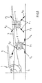
- FIG. 1 schematically represents, front view, the right part of a jet plane 1 of the type with engines 2 suspended under the wings 3 of the plane.
- the airplane rolls on the ground S and the door reversers 4 of the engines are in the deployed thrust reversal position.
- the direction of the reverse flow is indicated by the arrows F1 and F2.
- the arrows F1 show that the flow hits the ground, which is likely to cause stones to be thrown and especially hot air blows according to arrow F3 which can be re-ingested by the motors, with a risk of deterioration of these latter.
- the reverse flow along arrow F2 risks striking the horizontal tail 5 of the airplane, creating undesirable effects, in particular on the handling of the airplane.
- the inverted gas stream guidance system according to the invention which it is assumed that the left engine is equipped with, eliminates these drawbacks.
- the lower doors of the inverter equipped with the guide system G1 makes it possible to orient the reverse flow substantially according to the arrows F4 according to a trajectory which tangents the ground and spreads the flow laterally.
- the upper doors may be fitted with a similar guidance system G2 which will deflect the flow in an arrow F5 away from the horizontal tail 5.
- FIGS. 2 to 7 The ply guide system will now be described in more detail with reference to FIGS. 2 to 7. It is obvious that this system can be fitted to any type of inverter door to door and applies to fixed motors not only, such as in FIG. 1, under the wing, but also to engines arranged in any other place on the aircraft.
- the thrust reverser is constituted by several doors 4 articulated so as to tilt around an axis A under the action of a jack.
- control V between a so-called “cruising” position in which the door is aligned with the cover parts C and completely releases the annular channel CA and a so-called “inversion” position shown in solid line in FIG. 2 and in which the downstream part of the door closes the channel CA while its upstream part projects outside the cowling so as to deflect the flow Fx radially outwards and upstream.
- the door 4 has on its upstream edge 11 at least one front deflector structure, or spoiler, generally designated at D and extending from the internal face of the door.
- the invention relates to the particular construction of this deflecting structure which allows lateral guidance of the diverted flow.
- This deflecting structure in the embodiment shown, given by way of nonlimiting example, comprises a sole 10 fixed (by welding, riveting or bolting) against the edge 11 of the door. At its ends, the sole is extended upwards by two lateral members 12 and 13 (FIG. 3) which form with the sole 10 a U-shaped frame delimiting an empty space 14. The upper end of the members 12 and 13 is capped by a transverse stiffener 15.
- blades 16 shaped as a wing, the foot 17 of which is fixed to the sole 10 and the head 18 is fixed under the stiffener 15, the head 18 being longer than the foot 17.
- Figure 4 which is a top view of Figure 3, the blades 16 are substantially parallel to each other and are inclined at an angle a with respect to the normal N to the sole which can be between 0 ° and 70 ° according to the lateral orientation needs of the diverted flow.
- the rounded leading edge 19 of the vanes 16 is oriented towards the inside of the door, while their trailing edge 20 is turned towards the outside, the trailing edge which is situated in the same plane as the sole 10 and the members 12,13 of the deflector structure.
- the geometric center 21 of the root 17 of each blade is offset from the geometric center 22 of the blade head 18 by an angle b which can be between 0 ° and 30 °.
- the blades 16 have, seen from the front, a substantially trapezoidal shape, their trailing edge 20 being roughly perpendicular to the foot 17 and to the head 18 of the blade , while their leading edge 19 is inclined.
- the blade root 17 is shorter than the blade head 18.
- the stiffener 15 for its part, can advantageously also have an aerodynamic section in the shape of a wing with rounded leading edge 23 (FIG. 2) oriented towards the inside of the door and linear trailing edge 24 situated in the same plane. as the trailing edges of the blades 16.
- the angle c between the stiffener 15 and the plane of the U-shaped space 14 delimited by the frame 10, 11, 13 is between 30 ° and 90 °.
Landscapes
- Engineering & Computer Science (AREA)
- Chemical & Material Sciences (AREA)
- Combustion & Propulsion (AREA)
- Mechanical Engineering (AREA)
- General Engineering & Computer Science (AREA)
- Structures Of Non-Positive Displacement Pumps (AREA)
- Body Structure For Vehicles (AREA)
- Turbine Rotor Nozzle Sealing (AREA)
Description
La présente invention concerne un inverseur de poussée de type à portes basculantes destiné à équiper un moteur à réaction. Dans ce type d'inverseur connu, les portes sont conçues pour évoluer entre deux positions, à savoir une position dite "de croisière" dans laquelle elles constituent des éléments de capotage d'un canal d'éjection des gaz permettant une circulation du flux de gaz d'amont en aval, et une position dite "d'inversion de poussée" dans laquelle les portes, après basculement, obturent au moins partiellement le canal d'éjection et dévient un flux de gaz radialement vers l'extérieur et vers l'amont.The present invention relates to a thrust reverser of the overhead door type intended to equip a jet engine. In this type of known reverser, the doors are designed to move between two positions, namely a so-called "cruising" position in which they constitute cover elements for a gas ejection channel allowing circulation of the flow of upstream downstream gas, and a so-called "thrust reversal" position in which the doors, after tilting, at least partially close the ejection channel and deflect a gas flow radially outward and inward upstream.
Plus particulièrement, l'invention propose un perfectionnement aux portes d'inverseur connues dans lesquelles, afin d'aider à l'inversion et au guidage du flux dévié, on prévoit au moins une structure déflectrice s'étendant à peu près perpendiculairement à la porte à partir de la face interne de celle-ci, structure déflectrice située à l'extrémité amont de la porte et/ou sur les bords latéraux de celle-ci. On a déjà proposé, notamment dans la demande de brevet EP-A-558 381, faisant partie de l'Etat de la technique selon l'Article 54(3) CBE, au nom de la demanderesse, une configuration de structure déflectrice destinée à assurer un contrôle de la direction du jet dévié, ceci pour éviter le phénomène de ré-ingestion par le moteur et/ou les interférences du jet dévié avec les structures, notamment de la voilure de l'avion.More particularly, the invention proposes an improvement to known reverser doors in which, in order to assist in reversing and guiding the deflected flow, at least one deflector structure is provided which extends approximately perpendicularly to the door. from the internal face of the latter, deflecting structure situated at the upstream end of the door and / or on the lateral edges of the latter. We have already proposed, in particular in patent application EP-A-558 381, forming part of the state of the art according to Article 54 (3) EPC, in the name of the applicant, a configuration of deflector structure intended to ensure control of the direction of the deflected jet, this to avoid the phenomenon of re-ingestion by the engine and / or interference of the deflected jet with the structures, in particular of the aircraft wing.
La solution décrite dans cette demande de brevet antérieure consiste à ménager dans l'épaisseur d'une plaque déflectrice, une série d'ouvertures de profil spécial qui permet d'imposer aux veines de gaz dévié une orientation privilégiée.The solution described in this earlier patent application consists in providing, in the thickness of a deflector plate, a series of openings of special profile which makes it possible to impose on the veins of deflected gas a preferred orientation.
Si une telle disposition s'est révélée efficace en général, elle présente cependant des limites pour certains cas particuliers, notamment pour les moteurs disposés sous voilure, qui requièrent une orientation de la nappe déviée selon des angles beaucoup plus fermés.If such an arrangement has proved effective in general, it nevertheless has limits for certain particular cases, in particular for the motors arranged under sails, which require an orientation of the deflected layer according to much more closed angles.
La configuration nouvelle de la structure déflectrice objet de la présente invention a pour but de répondre à ce problème. Dans cette optique, l'inverseur selon l'invention se caractérise par le fait que ladite structure déflectrice est constituée par :
- une semelle fixée sur le bord de la porte,
- un raidisseur transversal écarté de ladite semelle et délimitant, avec elle, un espace vide, et
- une série d'aubes déflectrices logées dans ledit espace vide, entre la semelle et le raidisseur, et fixées à ladite semelle et audit raidisseur.
- a sole fixed to the edge of the door,
- a transverse stiffener spaced from said sole and defining, with it, an empty space, and
- a series of deflecting vanes housed in said empty space, between the sole and the stiffener, and fixed to said sole and to said stiffener.
On connaît, certes, d'après FR-A-2 681 101, un inverseur à portes dont les portes comportent une structure déflectrice 13 (ou becquet) perpendiculaire à la porte (figures 4 et 5), mais cette structure est pleine et les éléments en forme d'aube 23 sont fixés entre la structure 13 et le fond de la porte. Le flux d'air ne peut pas, selon ce document, traverser la structure 13 entre les aubes qui ne sont pas logées dans un espace vide ménagé entre un raidisseur écarté et une semelle. Dans la forme de réalisation de la figure 7 de FR-A-2 681 101, les éléments 123 en forme d'aubes font saillie à partir du fond de la porte. Dans ce cas non plus, il n'existe pas de passage vide entre les aubes permettant au flux de traverser la porte.We know, of course, from FR-A-2 681 101, a door reverser whose doors have a deflector structure 13 (or spoiler) perpendicular to the door (Figures 4 and 5), but this structure is full and the blade-
Avantageusement, selon l'invention, le raidisseur transversal et la semelle sont solidaires de façon à constituer un cadre indéformable, la semelle présentant à ses deux extrémités des membrures latérales délimitant avec la semelle un espace en U où sont logées les aubes, le raidisseur transversal étant fixé aux extrémités libres des membrures latérales.Advantageously, according to the invention, the transverse stiffener and the sole are integral so as to constitute a non-deformable frame, the sole having at its two ends lateral members delimiting with the sole a U-shaped space where the blades are housed, the transverse stiffener being attached to the free ends of the side members.
Afin d'obtenir un effet d'orientation particulièrement efficace de la nappe déviée, les aubes déflectrices ont un profil aérodynamique en forme d'aile dont le bord d'attaque, de préférence arrondi, est orienté vers l'intérieur de la porte et le bord de fuite est situé dans le même plan que la semelle de la structure déflectrice.In order to obtain a particularly effective orientation effect of the deflected ply, the deflecting vanes have an aerodynamic profile in the shape of a wing whose leading edge, preferably rounded, is oriented towards the inside of the door and the trailing edge is located in the same plane as the sole of the deflector structure.
Les aubes sont sensiblement parallèles entre elles et sont inclinées d'un angle compris entre 0° et 70° par rapport à la normale au plan de la semelle (angle d'attaque). De même, le centre géométrique de l'extrémité de chaque aube liée à la semelle est décalé par rapport au centre géométrique de l'extrémité de l'aube liée au raidisseur d'un angle compris entre 0° et 30°.The blades are substantially parallel to each other and are inclined at an angle between 0 ° and 70 ° relative to the normal to the plane of the sole (angle of attack). Similarly, the geometric center of the end of each blade linked to the sole is offset from the geometric center of the end of the blade linked to the stiffener by an angle between 0 ° and 30 °.
Par ailleurs, le raidisseur transversal aura avantageusement une section en forme d'aile avec bord d'attaque arrondi orienté vers l'intérieur de la porte et bord de fuite situé dans le même plan que les bords de fuite des aubes.Furthermore, the transverse stiffener will advantageously have a wing-shaped section with rounded leading edge oriented towards the inside of the door and trailing edge located in the same plane as the trailing edges of the blades.
D'autres caractéristiques de l'invention apparaîtront au cours de la description d'une forme de réalisation de la présente invention en référence aux dessins annexés dans lesquels :
- la figure 1 représente schématiquement un avion équipé de moteurs situés sous la voilure et auxquels la présente invention est particulièrement adaptée ;
- la figure 2 représente, vue de côté, une porte d'inverseur équipée de la structure déflectrice selon l'invention ;
- la figure 3 est une vue en perspective de la structure déflectrice ;
- la figure 4 est une vue de dessus ;
- la figure 5 est une vue de côté d'une aube ;
- les figures 6 et 7 sont des vues en coupe de chaque extrémité de l'aube de la figure 5, respectivement selon les lignes VI-VI et VII-VII ; et
- la figure 8 représente une porte d'inverseur déployée équipée du système de l'invention et montrant le guidage des nappes déviées par rapport au sol.
- FIG. 1 schematically represents an aircraft equipped with engines located under the wing and to which the present invention is particularly suitable;
- 2 shows, side view, an inverter door equipped with the deflector structure according to the invention;
- Figure 3 is a perspective view of the deflector structure;
- Figure 4 is a top view;
- Figure 5 is a side view of a blade;
- Figures 6 and 7 are sectional views of each end of the blade of Figure 5, respectively along lines VI-VI and VII-VII; and
- FIG. 8 represents a deployed reverser door fitted with the system of the invention and showing the guidance of the plies deviated with respect to the ground.
La figure 1 représente schématiquement, vue de face, la partie droite d'un avion à réaction 1 du type à moteurs 2 suspendus sous les ailes 3 de l'avion. Lors de l'atterrissage, l'avion roule sur le sol S et les inverseurs à portes 4 des moteurs sont en position d'inversion de poussée déployée. Comme on le voit sur le moteur de droite de la figure 1, que l'on considère comme n'étant pas équipé du système de guidage de nappe faisant l'objet de l'invention, la direction du flux inversé est matérialisée par les flèches F1 et F2. Les flèches F1 montrent que le flux vient frapper le sol, ce qui risque d'entraîner des projections de pierres et surtout des renvois d'air chaud selon la flèche F3 qui peuvent être ré-ingérés par les moteurs, avec un risque de détérioration de ces derniers. De même, le flux inversé selon la flèche F2 risque de heurter l'empennage horizontal 5 de l'avion en créant des effets indésirables, notamment sur la maniabilité de l'avion.FIG. 1 schematically represents, front view, the right part of a
Le système de guidage des veines de gaz inversé selon l'invention dont on suppose que le moteur de gauche est équipé permet d'éliminer ces inconvénients. Ainsi, les portes inférieures de l'inverseur équipé du système de guidage G1 permet d'orienter le flux inversé sensiblement selon les flèches F4 selon une trajectoire qui tangente le sol et écarte le flux latéralement. Les portes supérieures pourront être équipées d'un système de guidage similaire G2 qui déviera le flux selon une flèche F5 à l'écart de l'empennage horizontal 5.The inverted gas stream guidance system according to the invention, which it is assumed that the left engine is equipped with, eliminates these drawbacks. Thus, the lower doors of the inverter equipped with the guide system G1 makes it possible to orient the reverse flow substantially according to the arrows F4 according to a trajectory which tangents the ground and spreads the flow laterally. The upper doors may be fitted with a similar guidance system G2 which will deflect the flow in an arrow F5 away from the
On décrira à présent plus en détail le système de guidage de nappe en référence aux figures 2 à 7. Il est évident que ce système peut équiper tout type de portes d'inverseur à portes et s'applique à des moteurs fixés non seulement, comme à la figure 1, sous voilure mais également à des moteurs disposés en tout autre endroit de l'avion.The ply guide system will now be described in more detail with reference to FIGS. 2 to 7. It is obvious that this system can be fitted to any type of inverter door to door and applies to fixed motors not only, such as in FIG. 1, under the wing, but also to engines arranged in any other place on the aircraft.
Comme cela est bien connu, l'inverseur de poussée est constitué par plusieurs portes 4 articulées de façon à basculer autour d'un axe A sous l'action d'un vérin de commande V entre une position dite "de croisière" dans laquelle la porte est alignée avec les parties de capotage C et libère totalement le canal annulaire CA et une position dite "d'inversion" représentée en trait plein à la figure 2 et dans laquelle la partie aval de la porte obture le canal CA tandis que sa partie amont fait saillie à l'extérieur du capotage de façon à dévier le flux Fx radialement vers l'extérieur et vers l'amont. Afin d'aider à l'inversion du flux, la porte 4 présente sur son bord amont 11 au moins une structure déflectrice frontale, ou becquet, désignée de façon générale en D et s'étendant à partir de la face interne de la porte.As is well known, the thrust reverser is constituted by
L'invention concerne la construction particulière de cette structure déflectrice qui permet un guidage latéral du flux dévié.The invention relates to the particular construction of this deflecting structure which allows lateral guidance of the diverted flow.
Cette structure déflectrice, dans la forme de réalisation représentée, donnée à titre d'exemple non limitatif, comporte une semelle 10 fixée (par soudage, rivetage ou boulonnage) contre le bord 11 de la porte. A ses extrémités, la semelle est prolongée vers le haut par deux membrures latérales 12 et 13 (figure 3) qui forment avec la semelle 10 un cadre en U délimitant un espace vide 14. L'extrémité supérieure des membrures 12 et 13 est coiffée par un raidisseur transversal 15.This deflecting structure, in the embodiment shown, given by way of nonlimiting example, comprises a sole 10 fixed (by welding, riveting or bolting) against the
Dans l'espace 14 sont logées des aubes 16 profilées en forme d'aile dont le pied 17 est fixé à la semelle 10 et la tête 18 est fixée sous le raidisseur 15, la tête 18 étant plus longue que le pied 17. Comme on le voit à la figure 4 qui est une vue de dessus de la figure 3, les aubes 16 sont sensiblement parallèles entre elles et sont inclinées d'un angle a par rapport à la normale N à la semelle qui peut être compris entre 0° et 70° selon les besoins d'orientation latérale du flux dévié.In
Le bord d'attaque 19 arrondi des aubes 16 est orienté vers l'intérieur de la porte, tandis que leur bord de fuite 20 est tourné vers l'extérieur, bord de fuite qui est situé dans le même plan que la semelle 10 et les membrures 12,13 de la structure déflectrice.The rounded leading
Par ailleurs, comme on le voit à la figure 3, le centre géométrique 21 du pied 17 de chaque aube est décalé par rapport au centre géométrique 22 de la tête 18 d'aube d'un angle b qui peut être compris entre 0° et 30°.Furthermore, as can be seen in FIG. 3, the
Comme on le voit particulièrement aux figures 2, 5, 6 et 7 les aubes 16 ont, vues de face, une forme sensiblement trapézoïdale, leur bord de fuite 20 étant à peu près perpendiculaire au pied 17 et à la tête 18 de l'aube, tandis que leur bord d'attaque 19 est incliné. Le pied d'aube 17 est plus court que la tête d'aube 18.As seen particularly in Figures 2, 5, 6 and 7 the
Le raidisseur 15, quant à lui, peut avantageusement présenter également une section aérodynamique en forme d'aile avec bord d'attaque arrondi 23 (figure 2) orienté vers l'intérieur de la porte et bord de fuite linéaire 24 situé dans le même plan que les bords de fuite des aubes 16.The
Enfin, l'angle c entre le raidisseur 15 et le plan de l'espace en U 14 délimité par le cadre 10,11,13 est compris entre 30° et 90°.Finally, the angle c between the
Claims (10)
- A thrust reverser for a jet engine of the type with pivoting doors (4) capable of moving between two positions, namely a so-called "cruising" position in which the doors (4) constitute fairing elements (C) for a duct for ejecting (CA) the gases allowing the flow of gas to circulate from upstream to downstream, and a so-called "thrust reversal" position in which the doors (4), after pivoting, at least partially close off the ejection duct (CA) and divert a flow of gas radially outward and upstream, each of said doors (4) including, on its upstream edge (11), a deflecting structure (D) extending more or less perpendicularly to the door (4) and intended to guide the diverted flow, said reverser being characterized in that said deflecting structure (D) consists of :- a sole plate (10) fixed to the edge (11) of the door (4),- a transverse stiffener (15) separated from said sole plate (10) and delimiting, with it, an empty space (14), and- a series of deflecting vanes (16), housed in said empty space (14), between the sole plate (10) and the stiffener (15), and fixed to said sole plate and to said stiffener.
- The reverser as claimed in claim 1, wherein the transverse stiffener (15) and the sole plate (10) are secured so as to constitute an indeformable frame.
- The reverser as claimed in claim 1 or 2, wherein the sole plate (10) has, at its two ends, lateral members (12,13) delimiting, with the sole plate, a U-shaped space (14) in which the vanes (16) are housed.
- The reverser as claimed in claim 3, wherein the transverse stiffener (15) is fixed to the free ends of the lateral members (12,13).
- The reverser as claimed in any one of claims 1 to 4, wherein the deflecting vanes (16) have an aerodynamic profile in the form of a wing, the leading edge (19) of which is oriented toward the inside of the door (4), and the trailing edge (20) of which is located in the same plane as the sole plate (10) of the deflecting structure (D).
- The thrust reverser as claimed in any one of claims 1 to 5, wherein the deflecting vanes (16) are substantially parallel to each other and are inclined by an angle a lying between 0° and 70° with respect to the normal (N) to the plane of the sole plate (angle of attack).
- The thrust reverser as claimed in any one of claims 1 to 6, wherein the geometric center (21) of the end of each vane (16) connected to the sole plate (10) is offset with respect to the geometric center (22) of the end of the vane connected to the transverse stiffener (15) by an angle b lying between 0° and 30°.
- The thrust reverser as claimed in any one of claims 1 to 7, wherein the transverse stiffener (15) has a cross section in the form of a wing with rounded leading edge (23) oriented toward the inside of the door and trailing edge (24) located in the same plane as the trailing edges of the vanes.
- The thrust reverser as claimed in any one of claims 1 to 8, wherein the end (18) of the vane connected to the transverse stiffener (15) is longer than the end (17) connected to the sole plate.
- The thrust reverser as claimed in any one of claims 3 to 9, wherein the transverse stiffener forms an angle c lying between 30° and 90° with the plane of the U-shaped space (14) delimited by the sole plate and its two lateral members.
Applications Claiming Priority (2)
| Application Number | Priority Date | Filing Date | Title |
|---|---|---|---|
| FR9214615A FR2698913B1 (en) | 1992-12-04 | 1992-12-04 | Door thrust reverser assembly equipped with a jet control device. |
| FR9214615 | 1992-12-04 |
Publications (2)
| Publication Number | Publication Date |
|---|---|
| EP0601910A1 EP0601910A1 (en) | 1994-06-15 |
| EP0601910B1 true EP0601910B1 (en) | 1997-03-19 |
Family
ID=9436228
Family Applications (1)
| Application Number | Title | Priority Date | Filing Date |
|---|---|---|---|
| EP93402875A Expired - Lifetime EP0601910B1 (en) | 1992-12-04 | 1993-11-29 | Thrust reverser door with deflector vanes to guide the jet |
Country Status (4)
| Country | Link |
|---|---|
| US (1) | US5396762A (en) |
| EP (1) | EP0601910B1 (en) |
| DE (1) | DE69309007T2 (en) |
| FR (1) | FR2698913B1 (en) |
Families Citing this family (21)
| Publication number | Priority date | Publication date | Assignee | Title |
|---|---|---|---|---|
| FR2738291B1 (en) * | 1995-09-06 | 1997-09-26 | Hispano Suiza Sa | TURBOREACTOR DRIVE INVERTER WITH DOORS ASSOCIATED WITH AN UPSTREAM PANEL FORMING SCOOP |
| EP0763653B1 (en) * | 1995-09-13 | 2001-07-18 | SOCIETE DE CONSTRUCTION DES AVIONS HUREL-DUBOIS (société anonyme) | Thrust reverser door with jet deflection cascade |
| US5794433A (en) * | 1996-06-18 | 1998-08-18 | The Nordam Group, Inc. | Thrust reverser door side fillers |
| US5915651A (en) * | 1997-07-10 | 1999-06-29 | Mcdonnell Douglas Corporation | Reverse thrust inlet vortex inhibitor |
| FR2776023B1 (en) * | 1998-03-12 | 2000-04-07 | Hispano Suiza Sa | TURBOREACTOR DRIVE INVERTER WITH SCOOPING DOORS ASSOCIATED WITH A MOBILE GRID |
| US6311928B1 (en) | 2000-01-05 | 2001-11-06 | Stage Iii Technologies, L.C. | Jet engine cascade thrust reverser for use with mixer/ejector noise suppressor |
| FR2887854B1 (en) * | 2005-06-30 | 2008-08-08 | Airbus France Sas | PLATFORM FOR AN AIRCRAFT AND AN AIRCRAFT PROVIDED WITH AT LEAST ONE SUCH NACELLE |
| US8015797B2 (en) * | 2006-09-21 | 2011-09-13 | Jean-Pierre Lair | Thrust reverser nozzle for a turbofan gas turbine engine |
| US7735778B2 (en) * | 2007-11-16 | 2010-06-15 | Pratt & Whitney Canada Corp. | Pivoting fairings for a thrust reverser |
| US8172175B2 (en) | 2007-11-16 | 2012-05-08 | The Nordam Group, Inc. | Pivoting door thrust reverser for a turbofan gas turbine engine |
| US8091827B2 (en) | 2007-11-16 | 2012-01-10 | The Nordam Group, Inc. | Thrust reverser door |
| US8051639B2 (en) * | 2007-11-16 | 2011-11-08 | The Nordam Group, Inc. | Thrust reverser |
| US8052085B2 (en) | 2007-11-16 | 2011-11-08 | The Nordam Group, Inc. | Thrust reverser for a turbofan gas turbine engine |
| US8052086B2 (en) * | 2007-11-16 | 2011-11-08 | The Nordam Group, Inc. | Thrust reverser door |
| US8127530B2 (en) | 2008-06-19 | 2012-03-06 | The Nordam Group, Inc. | Thrust reverser for a turbofan gas turbine engine |
| FR2955154B1 (en) * | 2010-01-08 | 2012-01-06 | Airbus Operations Sas | THRUST INVERTER FOR TURBO AIRCRAFT WITH DOUBLE FLOW SEMI-BURIAL |
| WO2014074144A1 (en) * | 2012-11-12 | 2014-05-15 | United Technologies Corporation | Clocked thrust reversers |
| US9944401B2 (en) | 2012-12-11 | 2018-04-17 | United Technologies Corporation | Asymmetric thrust reversers |
| FR3082889A1 (en) * | 2018-06-26 | 2019-12-27 | Airbus Operations | TURBOREACTOR COMPRISING A NACELLE EQUIPPED WITH REVERSING SHUTTERS PROVIDED WITH MEANS FOR GENERATING VORTS |
| FR3092145A1 (en) * | 2019-01-24 | 2020-07-31 | Airbus Operations | DOUBLE-FLOW TURBOREACTOR CONTAINING A SERIES OF ROTATING BLADES TO CLOSE THE SECONDARY FLOW VEIN |
| FR3105986B1 (en) * | 2020-01-02 | 2021-12-03 | Safran Nacelles | Door thrust reverser including a deflector to redirect an upstream air flow |
Family Cites Families (13)
| Publication number | Priority date | Publication date | Assignee | Title |
|---|---|---|---|---|
| US3097484A (en) * | 1960-06-13 | 1963-07-16 | Thrust reversers for jet engines | |
| US3303653A (en) * | 1965-06-30 | 1967-02-14 | Gen Electric | Lightweight thrust reverser |
| FR1529361A (en) * | 1966-06-29 | 1968-06-14 | Rolls Royce | Thrust reverser device |
| US3500644A (en) * | 1968-04-10 | 1970-03-17 | Rohr Corp | Thrust reverser |
| FR2126922B1 (en) * | 1971-01-20 | 1975-01-17 | Snecma | |
| US4216923A (en) * | 1977-03-30 | 1980-08-12 | Boeing Commercial Airplane Company | Target type thrust reverser |
| GB2185719B (en) * | 1986-01-25 | 1989-11-01 | Rolls Royce | Fluid flow reversing apparatus |
| FR2618852B1 (en) * | 1987-07-29 | 1989-11-10 | Hispano Suiza Sa | TURBOREACTOR DRIVE INVERTER PROVIDED WITH A FLOW RECTIFIER DEVICE |
| FR2618853B1 (en) * | 1987-07-29 | 1989-11-10 | Hispano Suiza Sa | TURBOREACTOR DRIVE INVERTER WITH MOBILE DOOR DEFLECTOR |
| FR2651278B1 (en) * | 1989-08-23 | 1994-05-06 | Hispano Suiza | INVERTER WITH GRIDS WITHOUT SLIDING COVER FOR TURBOREACTOR. |
| US5228641A (en) * | 1991-08-15 | 1993-07-20 | Rohr, Inc. | Cascade type aircraft engine thrust reverser with hidden link actuator |
| FR2681101B1 (en) * | 1991-09-11 | 1993-11-26 | Hispano Suiza | PUSH INVERTER WITH IMPROVED PILOTAGE OF REVERSE FLOW PATCHES. |
| FR2687733B1 (en) * | 1992-02-26 | 1995-08-04 | Hurel Dubois Avions | DRIVE INVERTER FOR A REACTION ENGINE PROVIDING GUIDANCE OF THE DEVIATED FLOW. |
-
1992
- 1992-12-04 FR FR9214615A patent/FR2698913B1/en not_active Expired - Lifetime
-
1993
- 1993-11-29 EP EP93402875A patent/EP0601910B1/en not_active Expired - Lifetime
- 1993-11-29 DE DE69309007T patent/DE69309007T2/en not_active Expired - Lifetime
- 1993-12-01 US US08/160,424 patent/US5396762A/en not_active Expired - Lifetime
Also Published As
| Publication number | Publication date |
|---|---|
| FR2698913B1 (en) | 1995-02-03 |
| FR2698913A1 (en) | 1994-06-10 |
| US5396762A (en) | 1995-03-14 |
| DE69309007T2 (en) | 1997-10-16 |
| EP0601910A1 (en) | 1994-06-15 |
| DE69309007D1 (en) | 1997-04-24 |
Similar Documents
| Publication | Publication Date | Title |
|---|---|---|
| EP0601910B1 (en) | Thrust reverser door with deflector vanes to guide the jet | |
| CA2624005C (en) | Engine assembly for an aircraft comprising an engine as well as an engine mounting structure for such an engine | |
| EP0822327B1 (en) | Thrust reverser for a turbofan engine with thrust reverser doors which form scoops | |
| EP0806563B1 (en) | Doors with deflector vanes for a thrust reverser of a turbofan engine | |
| EP0777045B1 (en) | Thrust reverser with doors with linked rear panel | |
| EP0828934B1 (en) | Double door thrust reverser assembly | |
| FR2777043A1 (en) | TURBOSPROCKET DRIVE WITH SCOOPING DOORS ASSOCIATED WITH AN ARTICULATED EXTERNAL COVER | |
| FR2958624A1 (en) | AIRCRAFT TURBOHOMOTING MACHINE, COMPRISING AN INCOMING MOBILE REAR FLAP | |
| WO1999046498A1 (en) | Turbojet thrust reverser with doors forming scoops associated with a mobile grating | |
| EP0754849B1 (en) | Double flux turbine thrust reverser with asymmetric doors | |
| EP0821151A1 (en) | Thrust reverser for a jet engine with doors with a sliding panel | |
| WO2010061071A2 (en) | Nacelle integrated on a flying wing | |
| WO2011083256A1 (en) | Thrust reverser for an aircraft having semi-recessed turbofan engines | |
| EP3587784A1 (en) | Turbojet engine comprising a nacelle with inverter flaps provided with vortex generator means | |
| EP3947950B1 (en) | Door for thrust reverser of an aircraft propulsion assembly, comprising a flexible baffle | |
| FR2891255A1 (en) | Engine e.g. jet engine, assembly for aircraft, has outlet placed in rear with respect to rear engine mount, and heat exchanger system with exchanger arranged inside fairing that is entirely situated in rear with respect to engine mount | |
| FR2757570A1 (en) | Thrust reverser for aircraft gas turbine engine | |
| EP4085190B1 (en) | Door thrust reverser comprising a deflector for redirecting an air flow in the upstream direction | |
| EP3004613A1 (en) | Turbojet engine nacelle comprising a thrust reversing device with doors, comprising inner flanks on the sides of the opening | |
| BE1030173B1 (en) | MOBILE LEADING EDGE FLAP WITH MULTIPLE STRUCTURE PASSAGE PATHS | |
| WO2021136900A1 (en) | Door thrust reverser comprising a deflector for redirecting an air flow to a tail unit | |
| WO2021136899A1 (en) | Thrust reverser comprising doors forming an asymmetric deflection opening in the open position | |
| FR2964704A1 (en) | Device for orienting air flow deviated by thrust reverser of e.g. double flow propeller of commercial aircraft, has ailerons placed within air flow deviated by reverser, where ailerons has geometry to modify orientation of local air flow |
Legal Events
| Date | Code | Title | Description |
|---|---|---|---|
| PUAI | Public reference made under article 153(3) epc to a published international application that has entered the european phase |
Free format text: ORIGINAL CODE: 0009012 |
|
| AK | Designated contracting states |
Kind code of ref document: A1 Designated state(s): DE GB |
|
| 17P | Request for examination filed |
Effective date: 19941110 |
|
| GRAG | Despatch of communication of intention to grant |
Free format text: ORIGINAL CODE: EPIDOS AGRA |
|
| 17Q | First examination report despatched |
Effective date: 19960529 |
|
| GRAH | Despatch of communication of intention to grant a patent |
Free format text: ORIGINAL CODE: EPIDOS IGRA |
|
| GRAH | Despatch of communication of intention to grant a patent |
Free format text: ORIGINAL CODE: EPIDOS IGRA |
|
| GRAA | (expected) grant |
Free format text: ORIGINAL CODE: 0009210 |
|
| AK | Designated contracting states |
Kind code of ref document: B1 Designated state(s): DE GB |
|
| REF | Corresponds to: |
Ref document number: 69309007 Country of ref document: DE Date of ref document: 19970424 |
|
| GBT | Gb: translation of ep patent filed (gb section 77(6)(a)/1977) |
Effective date: 19970603 |
|
| PLBE | No opposition filed within time limit |
Free format text: ORIGINAL CODE: 0009261 |
|
| STAA | Information on the status of an ep patent application or granted ep patent |
Free format text: STATUS: NO OPPOSITION FILED WITHIN TIME LIMIT |
|
| 26N | No opposition filed | ||
| REG | Reference to a national code |
Ref country code: GB Ref legal event code: IF02 |
|
| PGFP | Annual fee paid to national office [announced via postgrant information from national office to epo] |
Ref country code: GB Payment date: 20120926 Year of fee payment: 20 |
|
| PGFP | Annual fee paid to national office [announced via postgrant information from national office to epo] |
Ref country code: DE Payment date: 20120926 Year of fee payment: 20 |
|
| REG | Reference to a national code |
Ref country code: DE Ref legal event code: R071 Ref document number: 69309007 Country of ref document: DE |
|
| REG | Reference to a national code |
Ref country code: DE Ref legal event code: R071 Ref document number: 69309007 Country of ref document: DE |
|
| REG | Reference to a national code |
Ref country code: GB Ref legal event code: PE20 Expiry date: 20131128 |
|
| PG25 | Lapsed in a contracting state [announced via postgrant information from national office to epo] |
Ref country code: DE Free format text: LAPSE BECAUSE OF EXPIRATION OF PROTECTION Effective date: 20131130 Ref country code: GB Free format text: LAPSE BECAUSE OF EXPIRATION OF PROTECTION Effective date: 20131128 |