EP1013863A2 - Hinge - Google Patents
Hinge Download PDFInfo
- Publication number
- EP1013863A2 EP1013863A2 EP99123776A EP99123776A EP1013863A2 EP 1013863 A2 EP1013863 A2 EP 1013863A2 EP 99123776 A EP99123776 A EP 99123776A EP 99123776 A EP99123776 A EP 99123776A EP 1013863 A2 EP1013863 A2 EP 1013863A2
- Authority
- EP
- European Patent Office
- Prior art keywords
- intermediate piece
- hinge
- legs
- hooks
- hook
- Prior art date
- Legal status (The legal status is an assumption and is not a legal conclusion. Google has not performed a legal analysis and makes no representation as to the accuracy of the status listed.)
- Granted
Links
Images


Classifications
-
- E—FIXED CONSTRUCTIONS
- E05—LOCKS; KEYS; WINDOW OR DOOR FITTINGS; SAFES
- E05D—HINGES OR SUSPENSION DEVICES FOR DOORS, WINDOWS OR WINGS
- E05D3/00—Hinges with pins
- E05D3/06—Hinges with pins with two or more pins
-
- E—FIXED CONSTRUCTIONS
- E05—LOCKS; KEYS; WINDOW OR DOOR FITTINGS; SAFES
- E05D—HINGES OR SUSPENSION DEVICES FOR DOORS, WINDOWS OR WINGS
- E05D7/00—Hinges or pivots of special construction
- E05D7/12—Hinges or pivots of special construction to allow easy detachment of the hinge from the wing or the frame
- E05D7/123—Hinges or pivots of special construction to allow easy detachment of the hinge from the wing or the frame specially adapted for cabinets or furniture
-
- E—FIXED CONSTRUCTIONS
- E05—LOCKS; KEYS; WINDOW OR DOOR FITTINGS; SAFES
- E05D—HINGES OR SUSPENSION DEVICES FOR DOORS, WINDOWS OR WINGS
- E05D5/00—Construction of single parts, e.g. the parts for attachment
- E05D5/02—Parts for attachment, e.g. flaps
-
- E—FIXED CONSTRUCTIONS
- E05—LOCKS; KEYS; WINDOW OR DOOR FITTINGS; SAFES
- E05D—HINGES OR SUSPENSION DEVICES FOR DOORS, WINDOWS OR WINGS
- E05D7/00—Hinges or pivots of special construction
- E05D7/04—Hinges adjustable relative to the wing or the frame
-
- E—FIXED CONSTRUCTIONS
- E05—LOCKS; KEYS; WINDOW OR DOOR FITTINGS; SAFES
- E05D—HINGES OR SUSPENSION DEVICES FOR DOORS, WINDOWS OR WINGS
- E05D7/00—Hinges or pivots of special construction
- E05D7/04—Hinges adjustable relative to the wing or the frame
- E05D7/0407—Hinges adjustable relative to the wing or the frame the hinges having two or more pins and being specially adapted for cabinets or furniture
-
- E—FIXED CONSTRUCTIONS
- E05—LOCKS; KEYS; WINDOW OR DOOR FITTINGS; SAFES
- E05Y—INDEXING SCHEME RELATING TO HINGES OR OTHER SUSPENSION DEVICES FOR DOORS, WINDOWS OR WINGS AND DEVICES FOR MOVING WINGS INTO OPEN OR CLOSED POSITION, CHECKS FOR WINGS AND WING FITTINGS NOT OTHERWISE PROVIDED FOR, CONCERNED WITH THE FUNCTIONING OF THE WING
- E05Y2900/00—Application of doors, windows, wings or fittings thereof
- E05Y2900/20—Application of doors, windows, wings or fittings thereof for furnitures, e.g. cabinets
Definitions
- the invention relates to a hinge with a substantially U-shaped hinge arm, the articulated, preferably by two articulated levers, with a pivotable Hinge part is connected and the one on an intermediate piece Base plate through an elongated hole at the end near the joint of the intermediate piece engaging annular groove of a joint adjustment screw and through Locking means is held.
- a hinge of this type is known from EP 0 369 261 B1, in which the intermediate piece by a clamping screw and the joint adjustment screw with the hinge arm is connected and made of plastic.
- the intermediate piece is on his Provide ends with hooks, one of which is resilient and one sloping ramp edge is provided so that the intermediate piece after hooking the articulated hook on the web part of a U-shaped base plate with which it can be locked that the resilient hook part is pressed down, until it snaps behind the opposite edge of the web part, with between the hook engages in a transverse opening of the web part Bead is provided.
- the hinge arm is through the plastic hooks made of plastic Intermediate piece connected to the base plate, so that between the hinge arm and the base plate is not given a very strong connection because of the intermediate plate consists of an elastic plastic.
- the object of the invention is therefore a hinge of the type specified to create that by a simple structure and by a better strength distinguished. Furthermore, the easy-to-assemble hinge should be a simple one Allow adjustment in height, to the side and in depth of the furniture.
- this object is achieved in that the intermediate piece with connected to the base plate and made of a substantially U-shaped part Sheet steel exists, the legs of which are opposite to the elongated hole Ends are provided with hooks, and that the web part of the intermediate piece between the hooks from a resilient tongue with an actuating piece on the end exists and in the area of the hook with a transverse recess is provided, in the arranged on the end region of the legs of the hinge arm Holding means, e.g. cones pointing inwards or a connecting leg Pen can be pressed in against the force of the resilient tongue in such a way that this locked between the bottom of the hook and a flank of the confiscation are.
- the intermediate piece with connected to the base plate and made of a substantially U-shaped part Sheet steel exists, the legs of which are opposite to the elongated hole Ends are provided with hooks, and that the web part of the intermediate piece between the hooks from a resilient tongue with an actuating piece on the end exists and in the area of the hook with a trans
- the intermediate piece in the hinge according to the invention consists of sheet steel, is the desired fixed connection between the hinge arm and the base plate guaranteed.
- the hinge arm can be easily on the intermediate piece snap on the ring groove of the joint adjustment screw into the engagement area of the freely running slot and then the opposite one End of the hinge arm is depressed so that the to Legs arranged locking means locking between the hook and the one Snap the flank of the retraction forming the abutment.
- the hinge according to the invention enables simple side adjustment of one for example, door carried by this only by actuating the joint adjustment screw, because the holding means locked in the hook jaws are one Form pivot axis about which the hinge arm pivot relative to the base plate leaves.
- An adjustment in the depth of the furniture is possible in that the intermediate piece in its web part with an elongated hole Fastening hole is provided through which the intermediate piece with the Base plate connecting fastening screw is screwed in.
- An adjustment the height is possible in that the base plate on both sides with wing-like Fastening flanges is provided, which extend transversely to the intermediate piece Oblong holes are provided through the fastening screws in the furniture wall are screwable.
- a particular advantage of the invention includes in that with the intermediate piece fixing screw fixing on the base plate even without it Attach the intermediate piece of the hinge arm directly to the base plate leaves.
- the web part of the hinge arm is provided with an elongated hole through that grips the fastening screw and that adjusts the hinge arm in the depth of the furniture.
- the intermediate piece can instead in Guides of the base plate e.g. be guided by an eccentric or it can also form a uniform base plate itself.
- the hooks in the direction point to the joint and bent an abutment out of the resilient tongue that is supported in the locked state on the pin or the pin, so that they are clamped between the hook and the abutment.
- the pins or the pin are supported the bottom of the open hook mouths towards the joint and are locked in this Position held by the abutment.
- the abutment creates a better one locking support, as guaranteed only by retraction of the flank is.
- the hooks to the rear point In order to create a firmer latching also in this embodiment, is provided in a further embodiment of the invention that the actuating part with laterally projecting projections is provided, which is pressed into the hook mouth Condition of the pins or the pin reach behind the rear sides of the legs.
- the legs carrying the hooks at its rear lower end areas expediently with the swivel path of the actuator limiting projections.
- the rear sides of the legs are expediently at their lower end regions beveled so that the inner edges of the projecting projections slide these sides, as it were, of wedge surfaces, until the exciting engagement can.
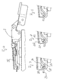
- FIGS. 1 to 5 there is the first embodiment of the invention Hinge from a base plate 1, one screwed to this Intermediate piece 2 and one snapped onto the intermediate piece 2 Hinge arm 3, articulated in the usual way by two links 3, 4 with one Pot-shaped pivotable hinge part 5 is connected.
- the base plate 1 consists of an elongated central section which is U-shaped in cross section 6, an elongated ramp-shaped elevation 7 is also bent out of its web part which is also U-shaped in cross section.
- the width of the ramp Elevation 7 is smaller than the width of the elongated central piece 6, so that 6 steps on both sides of the ramp-shaped elevation 7 on the web part of the center piece 10 are formed, the support of the lower edges of the legs 8 of the U-shaped Serve intermediate piece 2.
- the distance between the legs 8 corresponds of the intermediate piece 2 the width of the ramp-shaped elevation 7, so that the intermediate piece 2 is held on the base plate 1 without rotation.
- the lower margins the leg of the intermediate piece 2 are provided with tooth-like projections 9, which engage in corrugations provided on the steps 10 of the base plate 1.
- the base plate 1 is symmetrical to the transverse center line with wing-like extensions 11 provided, which form fastening flanges and which are provided with elongated holes, whose center lines are aligned with the transverse center line of the base plate. Through the elongated holes are fastening screws 12 screwed in, which the base plate 1 with a Connect furniture wall 13.
- the ramp-shaped elevation is crimped in its central area Provide threaded hole into which a fastening screw 14 can be screwed.
- the base plate 1 consists of a stamped sheet metal part.
- the intermediate plate 2 also consists of a U-shaped, hardened sheet metal stamping.
- the web part 15 is in its rear end region with side cutouts 16 provided, through which a resilient tongue 17 is cut free.
- the resilient tongue has a widened by hand operable at its rear end Actuating part 18 on
- the side legs 8 are in their rear end region provided with hooks 19 pointing towards the joint end.
- this hook is the resilient tongue 17 with a groove-shaped depression provided, which can be seen from Fig. 3.
- In front of the top of this gutter-shaped Recess is from the resilient tongue 17 another against the hook 19 Tongue 20 bent out, which is an abutment for the in the hook jaws the hook 19 form lockable pin 21.
- the web part 15 is in the form of a keyhole Provide an elongated hole for the fastening screw 14.
- the slot is through one narrower rectangular section 22 extended into the resilient tongue 17, so that the elasticity-improving resilient webs 23 are formed.
- the web part At its front end, the web part has a freely running elongated hole 24.
- the hinge arm 3 is in its web part with a flanged threaded hole provided, in which the joint adjusting screw 26 is screwed. This points in her lower end area an annular groove 27 with which this in the bottom of the free outgoing slot 24 engages.
- the hinge arm 3 At its rear end is the hinge arm 3 with one of its legs 28 connecting pin 21 provided, which can be locked in the hook jaws of the hook 19 is.
- the base plate 1 is first by the fastening screws 12 connected to the furniture side wall 13. With the base plate 1, the intermediate piece 2 is screwed by the fastening screw 14, wherein the head of the fastening screw 14 on the countersunk edges 30 of the supports keyhole-shaped elongated hole.
- the hinge arm 3 is thereby with the Intermediate plate 2 locked that the annular groove 27 of the joint adjusting screw 26 in the free tapered oblong hole 24 is inserted until shortly before its engagement position is in which the pin in front of the mouths of the hook 19 rests on the abutment 20.
- the hinge arm 3 By pressing on the rear end area of the hinge arm, the resilient Tongue 17 pressed down so that the pin 21 snaps into the hook mouth and is held in this by the end edge of the abutment 20.
- the hinge arm 3 By locking the pin 20 in the mouth of the hook 19, the hinge arm 3 is a short Moved backward so that the annular groove 27 engages with the narrowing Part of the slot 24 comes.
- the actuating part 18 is pressed down.
- the legs are 8 of the intermediate piece 2 provided at its rear ends with extensions 31 which a Prevent overpressure.
- the hinge arm 3 can also be used without the intermediate piece 2 directly through the fastening screw 14 with the base plate 1 connect.
- a joint adjustment screw 33 provided, which is then directly on the base-like elevation 7 supports.
- the fastening screw 14 can be loosened or tightened accordingly.
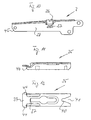
- FIGS. 6 to 12 differs from FIG. 1 to 5 essentially by a different design of the intermediate piece 35.
- Das Intermediate piece 35 is at the rear ends of their cut legs provided rearward-facing hook 36.
- the hooks have hook jaws 38, which, starting from a rounded base, have free-flowing flanks are.
- the cut-out resilient tongue 37 is in the area of the hook jaws 38 with a provided transverse groove-like depression. At its rear end the resilient tongue 37 carries an actuating part 39.
- the web part of the intermediate piece 35 is free on its side near the joint provided sloping hole 41, which then on its rounded Bottom has a narrowed section 40, the width of which narrowed Section 40 to the diameter of the shaft part of the joint adjusting screw 26 is adapted in the bottom of the annular groove 27.
- the actuating part 39 is on its sides with the legs 28 of the hinge arm 3 engaging extensions 44 provided. Reach behind when locked these extensions 44 the rear side edges of the legs 28 of the hinge arm 3rd
- the annular groove 27 is first narrowed into the longer one End part 40 of the elongated hole 41 used. Then the rear end of the hinge arm 3 in the manner shown in FIGS. 7 to 9, wherein the rear end regions of the legs 28 on the lateral extensions 44 of the Support actuator 39. Once the pin 21 is over the rounded top 42 of the hook 36 has entered the hook jaw 38, the hinge arm experiences by sliding on the beveled flanks 38 'of the hook mouths a slight one Movement towards the joint, causing the pin 21 to become increasingly complete enters the hook jaw 38.
Abstract
Description
Die Erfindung betrifft ein Scharnier mit einem im wesentlichen U-förmigen Scharnierarm, der gelenkig, vorzugsweise durch zwei Gelenkhebel, mit einem verschwenkbaren Scharnierteil verbunden ist und der über ein Zwischenstück an einer Grundplatte durch eine in ein frei auslaufendes Langloch am gelenknahen Ende des Zwischenstücks eingreifenden Ringnut einer Fugenverstellschraube und durch Rastmittel gehalten ist.The invention relates to a hinge with a substantially U-shaped hinge arm, the articulated, preferably by two articulated levers, with a pivotable Hinge part is connected and the one on an intermediate piece Base plate through an elongated hole at the end near the joint of the intermediate piece engaging annular groove of a joint adjustment screw and through Locking means is held.
Aus EP 0 369 261 B1 ist ein Scharnier dieser Art bekannt, bei dem das Zwischenstück durch eine Klemmschraube und die Fugenverstellschraube mit dem Scharnierarm verbunden ist und aus Kunststoff besteht. Das Zwischenstück ist an seinen Enden mit Haken versehen, von denen ein Haken federnd ausgebildet und mit einer schrägen Auflaufkante versehen ist, so daß das Zwischenstück nach Aufhaken des gelenkseitigen Hakens auf das Stegteil einer U-förmigen Grundplatte dadurch mit dieser verrastet werden kann, daß das federnde Hakenteil niedergedrückt wird, bis dieses hinter die gegenüberliegende Kante des Stegteils einrastet, wobei zwischen den Haken eine in eine quer verlaufende Öffnung des Stegteils eingreifende Wulst vorgesehen ist. Bei diesem bekannten Scharnier ist der Scharnierarm durch die aus Kunststoff bestehenden Haken des insgesamt aus Kunststoff bestehenden Zwischenstücks mit der Grundplatte verbunden, so daß zwischen dem Scharnierarm und der Grundplatte keine sehr feste Verbindung gegeben ist, weil die Zwischenplatte aus einem elastischen Kunststoff besteht.A hinge of this type is known from EP 0 369 261 B1, in which the intermediate piece by a clamping screw and the joint adjustment screw with the hinge arm is connected and made of plastic. The intermediate piece is on his Provide ends with hooks, one of which is resilient and one sloping ramp edge is provided so that the intermediate piece after hooking the articulated hook on the web part of a U-shaped base plate with which it can be locked that the resilient hook part is pressed down, until it snaps behind the opposite edge of the web part, with between the hook engages in a transverse opening of the web part Bead is provided. In this known hinge, the hinge arm is through the plastic hooks made of plastic Intermediate piece connected to the base plate, so that between the hinge arm and the base plate is not given a very strong connection because of the intermediate plate consists of an elastic plastic.
Aufgabe der Erfindung ist es daher, ein Scharnier der eingangs angegebenen Art zu schaffen, das sich durch einen einfachen Aufbau und durch eine bessere Festigkeit auszeichnet. Weiterhin soll das einfach zu montierende Scharnier eine einfache Einstellung in der Höhe, zur Seite und in der Tiefe des Möbels ermöglichen.The object of the invention is therefore a hinge of the type specified to create that by a simple structure and by a better strength distinguished. Furthermore, the easy-to-assemble hinge should be a simple one Allow adjustment in height, to the side and in depth of the furniture.
Erfindungsgemäß wird diese Aufgabe dadurch gelöst, daß das Zwischenstück mit der Grundplatte verbunden und aus einem im wesentlichen U-förmigen Teil aus Stahlblech besteht, dessen Schenkel an ihren den dem Langloch gegenüberliegenden Enden mit Haken versehen sind, und daß das Stegteil des Zwischenstücks zwischen den Haken aus einer federnden Zunge mit einem endseitigen Betätigungsstück besteht und im Bereich der Haken mit einer quer verlaufenden Einziehung versehen ist, in die an dem Endbereich der Schenkel des Scharnierarms angeordnete Haltemittel, z.B. nach innen weisende Zapfen oder ein die Schenkel verbindender Stift, gegen die Kraft der federnden Zunge derart eindrückbar sind, daß diese zwischen dem Grund der Haken und einer Flanke der Einziehung arretiert sind.According to the invention this object is achieved in that the intermediate piece with connected to the base plate and made of a substantially U-shaped part Sheet steel exists, the legs of which are opposite to the elongated hole Ends are provided with hooks, and that the web part of the intermediate piece between the hooks from a resilient tongue with an actuating piece on the end exists and in the area of the hook with a transverse recess is provided, in the arranged on the end region of the legs of the hinge arm Holding means, e.g. cones pointing inwards or a connecting leg Pen can be pressed in against the force of the resilient tongue in such a way that this locked between the bottom of the hook and a flank of the confiscation are.
Da bei dem erfindungsgemäßen Scharnier das Zwischenstück aus Stahlblech besteht, ist die gewünschte feste Verbindung zwischen Scharnierarm und Grundplatte gewährleistet. Der Scharnierarm läßt sich in einfacher Weise dadurch auf das Zwischenstück aufrasten, daß die Ringnut der Fugenverstellschraube in den Eingriffsbereich des frei auslaufenden Langlochs geschoben und anschließend das gegenüberliegende Ende des Scharnierarms niedergedrückt wird, so daß die an den Schenkeln angeordneten Haltemittel arretierend zwischen die Haken und die ein Widerlager bildende Flanke der Einziehung schnappen. Since the intermediate piece in the hinge according to the invention consists of sheet steel, is the desired fixed connection between the hinge arm and the base plate guaranteed. The hinge arm can be easily on the intermediate piece snap on the ring groove of the joint adjustment screw into the engagement area of the freely running slot and then the opposite one End of the hinge arm is depressed so that the to Legs arranged locking means locking between the hook and the one Snap the flank of the retraction forming the abutment.
Das erfindungsgemäße Scharnier ermöglicht eine einfache Seiteneinstellung einer beispielsweise von diesem getragenen Tür nur durch Betätigung der Fugenverstellschraube, weil die in den Hakenmäulern verrasteten Haltemittel gleichsam eine Schwenkachse bilden, um die sich der Scharnierarm relativ zu der Grundplatte verschwenken läßt. Eine Verstellung in der Tiefe des Möbels ist dadurch möglich, daß das Zwischenstück in seinem Stegteil mit einer aus einem Langloch bestehenden Befestigungsbohrung versehen ist, durch die eine das Zwischenstück mit der Grundplatte verbindende Befestigungsschraube eingeschraubt ist. Eine Verstellung der Höhe nach ist dadurch möglich, daß die Grundplatte beidseits mit flügelartigen Befestigungsflanschen versehen ist, die mit quer zu dem Zwischenstück verlaufenden Langlöchern versehen sind, durch die Befestigungsschrauben in die Möbelwand einschraubbar sind.The hinge according to the invention enables simple side adjustment of one for example, door carried by this only by actuating the joint adjustment screw, because the holding means locked in the hook jaws are one Form pivot axis about which the hinge arm pivot relative to the base plate leaves. An adjustment in the depth of the furniture is possible in that the intermediate piece in its web part with an elongated hole Fastening hole is provided through which the intermediate piece with the Base plate connecting fastening screw is screwed in. An adjustment the height is possible in that the base plate on both sides with wing-like Fastening flanges is provided, which extend transversely to the intermediate piece Oblong holes are provided through the fastening screws in the furniture wall are screwable.
Ein besonderer Vorteil der Erfindung besteht u.a. darin, daß sich mit der das Zwischenstück auf der Grundplatte fixierenden Befestigungsschraube auch ohne dieses Zwischenstück der Scharnierarm unmittelbar auf der Grundplatte befestigen läßt. Hierzu ist das Stegteil des Scharnierarms mit einem Langloch versehen, durch das die Befestigungsschraube greift und das eine Verstellung des Scharnierarms in der Tiefe des Möbels zuläßt.A particular advantage of the invention includes in that with the the intermediate piece fixing screw fixing on the base plate even without it Attach the intermediate piece of the hinge arm directly to the base plate leaves. For this purpose, the web part of the hinge arm is provided with an elongated hole through that grips the fastening screw and that adjusts the hinge arm in the depth of the furniture.
Bei einer anderen Ausführungsform kann aber das Zwischenstück statt dessen in Führungen der Grundplatte z.B. durch einen Exzenter verstellbar geführt sein oder es kann auch selbst eine einheitliche Grundplatte bilden.In another embodiment, however, the intermediate piece can instead in Guides of the base plate e.g. be guided by an eccentric or it can also form a uniform base plate itself.
Nach einer bevorzugten Ausführungsform ist vorgesehen, daß die Haken in Richtung auf das Gelenk weisen und aus der federnden Zunge ein Widerlager herausgebogen ist, das sich im verriegelten Zustand auf den Zapfen oder den Stift abstützt, so daß diese zwischen den Haken und dem Widerlager eingespannt sind. Bei dieser Ausführungsform der Erfindung stützen sich die Zapfen oder der Stift auf den Grund der zum Gelenk hin offenen Hakenmäuler ab und werden in dieser verriegelten Stellung durch das Widerlager gehalten. Das Widerlager schafft eine bessere verriegelnde Abstützung, als sie allein durch eine Einziehung der Flanke gewährleistet ist.According to a preferred embodiment it is provided that the hooks in the direction point to the joint and bent an abutment out of the resilient tongue that is supported in the locked state on the pin or the pin, so that they are clamped between the hook and the abutment. In this embodiment of the invention, the pins or the pin are supported the bottom of the open hook mouths towards the joint and are locked in this Position held by the abutment. The abutment creates a better one locking support, as guaranteed only by retraction of the flank is.
Nach einer anderen Ausführungsform ist vorgesehen, daß die Haken nach hinten weisen. Um auch bei dieser Ausführungsform eine festere Verrastung zu schaffen, ist in weiterer Ausgestaltung der Erfindung vorgesehen, daß das Betätigungsteil mit seitlich auskragenden Vorsprüngen versehen ist, die im in das Hakenmaul eingedrückte Zustand der Zapfen oder des Stifts die hinteren Seiten der Schenkel hintergreifen.According to another embodiment it is provided that the hooks to the rear point. In order to create a firmer latching also in this embodiment, is provided in a further embodiment of the invention that the actuating part with laterally projecting projections is provided, which is pressed into the hook mouth Condition of the pins or the pin reach behind the rear sides of the legs.
Um zu verhindern, daß die das Betätigungsstück tragende federnde Zunge überdrückt und dadurch verbogen werden kann, sind die die Haken tragenden Schenkel an ihren hinteren unteren Endbereichen zweckmäßigerweise mit den Schwenkweg des Betätigungsstücks begrenzenden Fortsätzen versehen.To prevent the resilient tongue carrying the actuator from overpressing and can thereby be bent, are the legs carrying the hooks at its rear lower end areas expediently with the swivel path of the actuator limiting projections.
Zweckmäßigerweise sind die hinteren Seiten der Schenkel an ihren unteren Endbereichen abgeschrägt, so daß die inneren Kanten der auskragenden Vorsprünge an diesen gleichsam Keilflächen bildenden Seiten bis zum spannenden Eingriff gleiten können.The rear sides of the legs are expediently at their lower end regions beveled so that the inner edges of the projecting projections slide these sides, as it were, of wedge surfaces, until the exciting engagement can.
Ein Ausführungsbeispiel der Erfindung wird nachstehend anhand der Zeichnung näher erläutert. In dieser zeigt
- Fig. 1
- eine Seitenansicht einer ersten Ausführungsform des erfindungsgemäßen Scharniers, teilweise im Schnitt,
- Fig. 2
- einen Längsschnitt durch den Scharnierarm des Scharniers nach Fig. 1,
- Fig. 3
- einen Längsschnitt durch das Zwischenstück des Scharniers nach Fig. 1,
- Fig. 4
- eine Draufsicht auf das Zwischenstück nach Fig. 3,
- Fig. 5
- eine Seitenansicht der Grundplatte des Scharniers nach Fig. 1,
- Fig. 6
- eine Seitenansicht einer zweiten Ausführungsform des erfindungsgemäßen Scharniers, teilweise im Schnitt,
- Fig. 7 bis 9
- unterschiedliche Stellungen des die Schenkel des Scharnierarms verbindenden Stifts während des Einrastens in das nach hinten offene Hakenmaul des Scharniers nach Fig. 6,
- Fig. 10
- einen Längsschnitt durch den Scharnierarm des Scharniers nach Fig. 6,
- Fig. 11
- einen Längsschnitt durch das Zwischenstück des Scharniers nach Fig. 6,
- Fig. 12
- eine Draufsicht auf das Zwischenstück nach Fig. 11 und
- Fig. 13
- eine Seitenansicht eines Scharniers, teilweise im Schnitt, bei dem der Scharnierarm ohne Zwischenstück mit der Grundplatte verschraubt ist.
- Fig. 1
- 2 shows a side view of a first embodiment of the hinge according to the invention, partly in section,
- Fig. 2
- 2 shows a longitudinal section through the hinge arm of the hinge according to FIG. 1,
- Fig. 3
- 2 shows a longitudinal section through the intermediate piece of the hinge according to FIG. 1,
- Fig. 4
- 3 shows a plan view of the intermediate piece according to FIG. 3,
- Fig. 5
- 2 shows a side view of the base plate of the hinge according to FIG. 1,
- Fig. 6
- 2 shows a side view of a second embodiment of the hinge according to the invention, partly in section,
- 7 to 9
- different positions of the pin connecting the legs of the hinge arm during engagement in the hook mouth of the hinge according to FIG. 6, which is open to the rear,
- Fig. 10
- 6 shows a longitudinal section through the hinge arm of the hinge according to FIG. 6,
- Fig. 11
- 6 shows a longitudinal section through the intermediate piece of the hinge according to FIG. 6,
- Fig. 12
- a plan view of the intermediate piece according to FIGS. 11 and
- Fig. 13
- a side view of a hinge, partially in section, in which the hinge arm is screwed to the base plate without an intermediate piece.
Wie aus den Fig. 1 bis 5 ersichtlich ist, besteht die erste Ausführungsform des erfindungsgemäßen
Scharniers aus einer Grundplatte 1, einem mit dieser verschraubten
Zwischenstück 2 und einem auf das Zwischenstück 2 aufgerasteten
Scharnierarm 3, der in üblicher Weise durch zwei Lenker 3, 4 gelenkig mit einem
topfförmigen verschwenkbaren Scharnierteil 5 verbunden ist.As can be seen from FIGS. 1 to 5, there is the first embodiment of the invention
Hinge from a base plate 1, one screwed to this
Die Grundplatte 1 besteht aus einem länglichen im Querschnitt U-förmigem Mittelteil
6, aus dessen Stegteil eine ebenfalls längliche rampenförmige Erhöhung 7 herausgebogen
ist, die ebenfalls im Querschnitt U-förmig ist. Die Breite der rampenförmigen
Erhöhung 7 ist kleiner als die Breite des länglichen Mittelstücks 6, so daß
beidseits der rampenförmigen Erhöhung 7 auf dem Stegteil des Mittelstücks 6 Stufen
10 gebildet sind, die der Abstützung der unteren Ränder der Schenkel 8 des U-förmigen
Zwischenstücks 2 dienen. Dabei entspricht der Abstand der Schenkel 8
des Zwischenstücks 2 der Breite der rampenförmigen Erhöhung 7, so daß das Zwischenstück
2 verdrehungsfrei auf der Grundplatte 1 gehalten ist. Die unteren Ränder
der Schenkel des Zwischenstücks 2 sind mit zahnartigen Vorsprüngen 9 versehen,
die in auf den Stufen 10 der Grundplatte 1 vorgesehene Riffelungen greifen. The base plate 1 consists of an elongated central section which is U-shaped in cross section
6, an elongated ramp-shaped elevation 7 is also bent out of its web part
which is also U-shaped in cross section. The width of the ramp
Elevation 7 is smaller than the width of the elongated central piece 6, so that
6 steps on both sides of the ramp-shaped elevation 7 on the web part of the
Die Grundplatte 1 ist symmetrisch zur Quermittellinie mit flügelartigen Fortsätzen 11
versehen, die Befestigungsflansche bilden und die mit Langlöchern versehen sind,
deren Mittellinien mit der Quermittellinie der Grundplatte fluchten. Durch die Langlöcher
sind Befestigungsschrauben 12 eingeschraubt, die die Grundplatte 1 mit einer
Möbelwand 13 verbinden.The base plate 1 is symmetrical to the transverse center line with wing-like extensions 11
provided, which form fastening flanges and which are provided with elongated holes,
whose center lines are aligned with the transverse center line of the base plate. Through the elongated holes
are fastening screws 12 screwed in, which the base plate 1 with a
Die rampenförmige Erhöhung ist in ihrem mittleren Bereich mit einer gebördelten
Gewindebohrung versehen, in die eine Befestigungsschraube 14 einschraubbar ist.The ramp-shaped elevation is crimped in its central area
Provide threaded hole into which a
Die Grundplatte 1 besteht insgesamt aus einem Blechstanzteil.The base plate 1 consists of a stamped sheet metal part.
Die Zwischenplatte 2 besteht ebenfalls aus einem U-förmigem, gehärteten Blechstanzteil.
Das Stegteil 15 ist in seinem hinteren Endbereich mit seitlichen Ausschnitten
16 versehen, durch die eine federnde Zunge 17 freigeschnitten ist. Die
federnde Zunge weist an ihrem hinteren Ende ein verbreitertes von Hand betätigbares
Betätigungsteil 18 auf Die seitlichen Schenkel 8 sind in ihrem hinteren Endbereich
mit zu dem gelenkseitigen Ende hin weisenden Haken 19 versehen. Im Bereich
dieser Haken ist die federnde Zunge 17 mit einer rinnenförmigen Vertiefung
versehen, die aus Fig. 3 ersichtlich ist. Vor dem Scheitel dieser rinnenförmigen
Vertiefung ist aus der federnden Zunge 17 eine weitere gegen die Haken 19 weisende
Zunge 20 herausgebogen, die ein Widerlager für den in den Hakenmäulern
der Haken 19 verrastbaren Stift 21 bilden.The
In seinem mittleren Bereich ist das Stegteil 15 mit einem schlüssellochförmigen
Langloch für die Befestigungsschraube 14 versehen. Das Langloch ist durch einen
schmaleren rechteckigen Abschnitt 22 bis in die federnde Zunge 17 hinein verlängert,
so daß die Elastizität verbessernde federnde Stege 23 gebildet sind.In its central region, the
An seinem vorderen Ende weist das Stegteil ein frei auslaufendes Langloch 24 auf.At its front end, the web part has a freely running elongated hole 24.
Der Scharnierarm 3 ist in seinem Stegteil mit einer gebördelten Gewindebohrung
versehen, in die die Fugenverstellschraube 26 eingeschraubt ist. Diese weist in ihrem
unteren Endbereich eine Ringnut 27 auf, mit der diese in den Grund des frei
auslaufenden Langlochs 24 greift.The
An ihrem rückwärtigen Ende ist der Scharnierarm 3 mit einem dessen Schenkel 28
verbindenden Stift 21 versehen, der in den Hakenmäulern der Haken 19 verrastbar
ist.At its rear end is the
Zur Montage des Scharnierarms 3 wird zunächst die Grundplatte 1 durch die Befestigungsschrauben
12 mit der Möbelseitenwand 13 verbunden. Mit der Grundplatte
1 ist durch die Befestigungsschraube 14 das Zwischenstück 2 verschraubt, wobei
sich der Kopf der Befestigungsschraube 14 auf den versenkten Rändern 30 des
schlüssellochförmigen Langlochs abstützt. Der Scharnierarm 3 wird dadurch mit der
Zwischenplatte 2 verrastet, daß die Ringnut 27 der Fugenverstellschraube 26 in
das frei auslaufende Langloch 24 bis kurz vor seine Eingriffsstellung eingeschoben
wird, in der der Stift vor den Mäulern der Haken 19 auf dem Widerlager 20 aufliegt.
Durch Druck auf den hinteren Endbereich des Scharnierarms wird die federnde
Zunge 17 nach unten gedrückt, so daß der Stift 21 in das Hakenmaul schnappt und
in diesem durch die Stirnkante des Widerlagers 20 gehalten wird. Durch die Verrastung
des Stifts 20 in dem Maul der Haken 19 wird der Scharnierarm 3 ein kurzes
Stück nach hinten bewegt, so daß die Ringnut 27 in Eingriff mit dem sich verengenden
Teil des Langlochs 24 kommt.To mount the
Zum Lösen der Rastverbindung wird das Betätigungsteil 18 nach unten gedrückt.
Um ein Überdrücken dieses Betätigungsteils zu verhindern, sind die Schenkel 8
des Zwischenstücks 2 an ihren hinteren Enden mit Fortsätzen 31 versehen, die ein
Überdrücken verhindern.To release the locking connection, the actuating
Wie aus Fig. 13 ersichtlich ist, läßt sich der Scharnierarm 3 auch ohne das Zwischenstück
2 unmittelbar durch die Befestigungsschraube 14 mit der Grundplatte 1
verbinden. Um eine Seiteneinstellung zu ermöglichen, ist eine Fugenverstellschraube
33 vorgesehen, die sich dann unmittelbar auf der sockelartigen Erhöhung
7 abstützt. Um eine Seiteneinstellung zu ermöglichen, muß die Befestigungsschraube
14 entsprechend gelöst oder nachgespannt werden.As can be seen from FIG. 13, the
Das Ausführungsbeispiel nach den Fig. 6 bis 12 unterscheidet sich von den Fig. 1
bis 5 im wesentlichen durch eine andere Ausbildung des Zwischenstücks 35. Das
Zwischenstück 35 ist an den hinteren Enden ihrer freigeschnittenen Schenkel mit
nach hinten weisenden Haken 36 versehen. Die Haken besitzen Hakenmäuler 38,
die ausgehend von einem abgerundeten Grund mit frei auslaufenden Flanken versehen
sind. Die rückwärtige Flanke 38' verläuft schräg nach hinten, so daß diese
eine Führungsbahn für den eindrückbaren Stift 21 bildet.The exemplary embodiment according to FIGS. 6 to 12 differs from FIG. 1
to 5 essentially by a different design of the
Die freigeschnittene federnde Zunge 37 ist im Bereich der Hakenmäuler 38 mit einer
querverlaufenden rinnenartigen Vertiefung versehen. An ihrem hinteren Ende
trägt die federnde Zunge 37 ein Betätigungsteil 39.The cut-out
Das Stegteil des Zwischenstücks 35 ist an seiner gelenknahen Seite mit einem frei
auslaufenden Langloch 41 versehen, das anschließend an seinen abgerundeten
Grund einen verengten Abschnitt 40 aufweist, wobei die Breite dieses verengten
Abschnitts 40 an den Durchmesser des Schaftteils der Fugenverstellschraube 26
im Grund der Ringnut 27 angepaßt ist.The web part of the
Das Betätigungsteil 39 ist an seinen Seiten mit die Schenkel 28 des Scharnierarms
3 hintergreifenden Fortsätzen 44 versehen. Im verrasteten Zustand hintergreifen
diese Fortsätze 44 die hinteren Seitenkanten der Schenkel 28 des Scharnierarms
3.The actuating
Zur Montage des Scharnierarms 3 auf dem mit der Grundplatte verschraubten Zwischenstück
wird zunächst die Ringnut 27 in den länger ausgebildeten verengten
Endteil 40 des Langlochs 41 eingesetzt. Sodann wird das hintere Ende des Scharnierarms
3 in der aus den Fig. 7 bis 9 ersichtlichen Weise niedergedrückt, wobei
sich die hinteren Endbereiche der Schenkel 28 auf den seitlichen Fortsätzen 44 des
Betätigungsteils 39 abstützen. Sobald der Stift 21 über die abgerundete Oberseite
42 des Hakens 36 in das Hakenmaul 38 eingetreten ist, erfährt der Scharnierarm
durch Abgleiten auf den abgeschrägten Flanken 38' der Hakenmäuler eine geringfügige
Bewegung in Richtung des Gelenks, wodurch der Stift 21 zunehmend vollständig
in das Hakenmaul 38 eintritt. Durch diese Verschiebung können die seitlichen
Fortsätze 44 die hinteren Kanten der Schenkel 28 schnappend hintergreifen,
wobei dieses Hintergreifen durch die keilförmigen Abschrägungen der hinteren
Kanten der Schenkel 28 des Scharnierarms 3 begünstigt wird. Die während des
Verrastungsvorgangs nach außen erfolgende Verschiebung des Scharnierarms 3
ist nur so gering, daß die Ringnut 27 der Fugenverstellschraube 26 nicht aus dem
verengten Teil 40 des Langlochs 41 austritt und somit noch in dem verengten Teil
40 gehalten ist.For mounting the
Zum Lösen der Rastverbindung wird das Betätigungsteil 39 nach unten gedrückt,
wobei an den hinteren Endbereichen der Schenkel des Zwischenstücks 35 Fortsätze
46 vorgesehen sind, die ein Überdrücken verhindern.To release the locking connection, the actuating
Claims (6)
dadurch gekennzeichnet,
characterized,
Priority Applications (1)
| Application Number | Priority Date | Filing Date | Title |
|---|---|---|---|
| SI9930421T SI1013863T1 (en) | 1998-12-21 | 1999-11-30 | Hinge |
Applications Claiming Priority (2)
| Application Number | Priority Date | Filing Date | Title |
|---|---|---|---|
| DE29822770U DE29822770U1 (en) | 1998-12-21 | 1998-12-21 | hinge |
| DE29822770U | 1998-12-21 |
Publications (3)
| Publication Number | Publication Date |
|---|---|
| EP1013863A2 true EP1013863A2 (en) | 2000-06-28 |
| EP1013863A3 EP1013863A3 (en) | 2002-10-02 |
| EP1013863B1 EP1013863B1 (en) | 2003-09-03 |
Family
ID=8066972
Family Applications (1)
| Application Number | Title | Priority Date | Filing Date |
|---|---|---|---|
| EP99123776A Expired - Lifetime EP1013863B1 (en) | 1998-12-21 | 1999-11-30 | Hinge |
Country Status (14)
| Country | Link |
|---|---|
| US (1) | US6446306B1 (en) |
| EP (1) | EP1013863B1 (en) |
| JP (1) | JP3357867B2 (en) |
| KR (1) | KR100395389B1 (en) |
| CN (1) | CN1113146C (en) |
| AT (1) | ATE248975T1 (en) |
| BR (1) | BR9907390A (en) |
| DE (2) | DE29822770U1 (en) |
| ES (1) | ES2207106T3 (en) |
| HK (1) | HK1028438A1 (en) |
| HU (1) | HU220687B1 (en) |
| PL (1) | PL337311A1 (en) |
| SI (1) | SI1013863T1 (en) |
| TW (1) | TW409162B (en) |
Families Citing this family (5)
| Publication number | Priority date | Publication date | Assignee | Title |
|---|---|---|---|---|
| DE20305835U1 (en) | 2003-04-10 | 2003-06-05 | Salice Arturo Spa | Brake deceleration adapter |
| US8839488B2 (en) * | 2006-06-20 | 2014-09-23 | Hardware Resources, Inc. | Adjustable hinge |
| CN101280655B (en) * | 2007-04-05 | 2011-11-16 | 川湖科技股份有限公司 | Hinge elastic force apparatus |
| US20080250604A1 (en) * | 2007-04-16 | 2008-10-16 | Ken-Ching Chen | Elastic device of a hinge |
| US8819897B2 (en) * | 2012-10-29 | 2014-09-02 | Hardware Resources, Inc. | Durable low-vibration long arm hinge apparatus |
Citations (1)
| Publication number | Priority date | Publication date | Assignee | Title |
|---|---|---|---|---|
| EP0369261B1 (en) | 1988-11-16 | 1992-08-05 | Julius Blum Gesellschaft m.b.H. | Hinge with a hinge arm |
Family Cites Families (15)
| Publication number | Priority date | Publication date | Assignee | Title |
|---|---|---|---|---|
| GB1185318A (en) * | 1966-11-21 | 1970-03-25 | Salice Arturo Spa | Self-Latching Hinge. |
| ATE93923T1 (en) * | 1984-10-19 | 1993-09-15 | Blum Gmbh Julius | HINGE. |
| US5056190A (en) * | 1984-10-19 | 1991-10-15 | Julius Blum Gesellschaft M.B.H. | Hinge with hinge arm releasably connected to mounting plate |
| DE3538888A1 (en) * | 1985-11-02 | 1987-05-07 | Praemeta | Hinge, especially furniture hinge |
| DE3639276A1 (en) * | 1986-11-17 | 1988-05-26 | Grass Alfred Metallwaren | FURNITURE HINGE WITH QUICK RELEASE |
| DE3841405A1 (en) * | 1988-06-29 | 1990-01-04 | Salice Arturo Spa | HINGED ARM WITH A FASTENING PLATE THAT FASTENS TO A FURNITURE PART OR THE LIKE. |
| JPH02176085A (en) * | 1988-12-27 | 1990-07-09 | Yogou Sumikin Sangyo Kk | Hinge |
| ES1009089Y (en) * | 1989-02-17 | 1989-12-16 | Blanco Eguiluz M. Begona | QUICK COUPLING DEVICE FOR FURNITURE HINGES. |
| DE9005706U1 (en) * | 1990-05-19 | 1990-07-26 | Julius Blum Ges.M.B.H., Hoechst, At | |
| DE9005813U1 (en) | 1990-05-22 | 1990-07-26 | Paul Hettich Gmbh & Co, 4983 Kirchlengern, De | |
| ES2086360T3 (en) | 1990-12-27 | 1996-07-01 | Lama | QUICK MOUNT FURNITURE HINGE. |
| DE9104498U1 (en) | 1991-04-14 | 1992-08-13 | Ed. Scharwaechter Gmbh & Co. Kg, 5630 Remscheid, De | |
| DE9109862U1 (en) | 1991-06-26 | 1992-08-13 | Grass Ag, Hoechst, Vorarlberg, At | |
| DE4236444C2 (en) * | 1992-10-28 | 1994-08-04 | Salice Arturo Spa | Hinge, preferably furniture hinge |
| US6061872A (en) * | 1998-03-02 | 2000-05-16 | Grass Gmbh | Cabinet hinge |
-
1998
- 1998-12-21 DE DE29822770U patent/DE29822770U1/en not_active Expired - Lifetime
-
1999
- 1999-11-26 KR KR10-1999-0052866A patent/KR100395389B1/en not_active IP Right Cessation
- 1999-11-30 DE DE59906851T patent/DE59906851D1/en not_active Expired - Fee Related
- 1999-11-30 SI SI9930421T patent/SI1013863T1/en unknown
- 1999-11-30 AT AT99123776T patent/ATE248975T1/en not_active IP Right Cessation
- 1999-11-30 EP EP99123776A patent/EP1013863B1/en not_active Expired - Lifetime
- 1999-11-30 ES ES99123776T patent/ES2207106T3/en not_active Expired - Lifetime
- 1999-12-01 TW TW088120955A patent/TW409162B/en not_active IP Right Cessation
- 1999-12-15 HU HU9904593A patent/HU220687B1/en not_active IP Right Cessation
- 1999-12-20 PL PL99337311A patent/PL337311A1/en not_active Application Discontinuation
- 1999-12-20 JP JP36048099A patent/JP3357867B2/en not_active Expired - Fee Related
- 1999-12-21 CN CN99126920A patent/CN1113146C/en not_active Expired - Fee Related
- 1999-12-21 US US09/468,566 patent/US6446306B1/en not_active Expired - Fee Related
- 1999-12-21 BR BR9907390-0A patent/BR9907390A/en not_active Application Discontinuation
-
2000
- 2000-12-01 HK HK00107735A patent/HK1028438A1/en not_active IP Right Cessation
Patent Citations (1)
| Publication number | Priority date | Publication date | Assignee | Title |
|---|---|---|---|---|
| EP0369261B1 (en) | 1988-11-16 | 1992-08-05 | Julius Blum Gesellschaft m.b.H. | Hinge with a hinge arm |
Also Published As
| Publication number | Publication date |
|---|---|
| ATE248975T1 (en) | 2003-09-15 |
| DE59906851D1 (en) | 2003-10-09 |
| CN1263196A (en) | 2000-08-16 |
| JP2000192718A (en) | 2000-07-11 |
| HU220687B1 (en) | 2002-04-29 |
| HU9904593D0 (en) | 2000-02-28 |
| EP1013863B1 (en) | 2003-09-03 |
| KR100395389B1 (en) | 2003-08-21 |
| EP1013863A3 (en) | 2002-10-02 |
| SI1013863T1 (en) | 2004-02-29 |
| PL337311A1 (en) | 2000-07-03 |
| HUP9904593A1 (en) | 2000-12-28 |
| BR9907390A (en) | 2001-01-16 |
| JP3357867B2 (en) | 2002-12-16 |
| DE29822770U1 (en) | 1999-02-18 |
| ES2207106T3 (en) | 2004-05-16 |
| CN1113146C (en) | 2003-07-02 |
| KR20000047729A (en) | 2000-07-25 |
| TW409162B (en) | 2000-10-21 |
| US6446306B1 (en) | 2002-09-10 |
| HK1028438A1 (en) | 2001-02-16 |
Similar Documents
| Publication | Publication Date | Title |
|---|---|---|
| EP0694669B1 (en) | Device for connecting a window glass with a window regulator | |
| DE2702643C3 (en) | Fitting for the detachable connection of two vertically abutting components, especially furniture parts | |
| EP1332077B1 (en) | Device for connecting a wiper arm to a wiper blade, a wiper blade and a wiper arm | |
| DE602004001734T2 (en) | A fastener for connection to a support member | |
| EP0528213B1 (en) | Fitting to be clamped in a profiled groove with at least one recess | |
| DE3841405C2 (en) | ||
| DE3026796C2 (en) | Hinge with a hinge arm and a mounting plate | |
| EP0043903A1 (en) | Hinge arm with mounting plate | |
| EP0058220A1 (en) | Connection fitting | |
| EP0066893A1 (en) | Joining fitting for detachably joining platelike furniture parts | |
| EP0205665B1 (en) | Handle to be fixed to a stud of a kitchen utensil | |
| EP0761130A2 (en) | Mounting fitting for drawer front panels | |
| DE19920137A1 (en) | Mounting plate for furniture hinges | |
| EP0080556A1 (en) | Sliding clamping lock for the detachable connection of two construction elements | |
| CH659613A5 (en) | FIXING CLAMP. | |
| DE3245056A1 (en) | Elastic clamp | |
| EP0275405B1 (en) | Connection fitting made of two parts | |
| EP0168595B1 (en) | Furniture hinge arm | |
| EP0256376B1 (en) | Hinge arm for a furniture hinge | |
| EP1013863B1 (en) | Hinge | |
| EP0274746B1 (en) | Clamp with adjustable jaws | |
| WO2010089065A1 (en) | Clamp device | |
| AT596U1 (en) | FITTING FOR DETACHABLE CONNECTING COMPONENTS | |
| DE19707741C2 (en) | hinge | |
| EP0255692B1 (en) | Hinge arm for a furniture hinge or the like |
Legal Events
| Date | Code | Title | Description |
|---|---|---|---|
| PUAI | Public reference made under article 153(3) epc to a published international application that has entered the european phase |
Free format text: ORIGINAL CODE: 0009012 |
|
| AK | Designated contracting states |
Kind code of ref document: A2 Designated state(s): AT BE CH CY DE DK ES FI FR GB GR IE IT LI LU MC NL PT SE |
|
| AX | Request for extension of the european patent |
Free format text: AL;LT;LV;MK;RO;SI PAYMENT 19991130 |
|
| PUAL | Search report despatched |
Free format text: ORIGINAL CODE: 0009013 |
|
| AK | Designated contracting states |
Kind code of ref document: A3 Designated state(s): AT BE CH CY DE DK ES FI FR GB GR IE IT LI LU MC NL PT SE |
|
| AX | Request for extension of the european patent |
Free format text: AL;LT;LV;MK;RO;SI PAYMENT 19991130 |
|
| RIC1 | Information provided on ipc code assigned before grant |
Free format text: 7E 05D 5/02 A, 7E 05D 7/12 B, 7E 05D 3/06 B, 7E 05D 7/04 B |
|
| 17P | Request for examination filed |
Effective date: 20021104 |
|
| GRAH | Despatch of communication of intention to grant a patent |
Free format text: ORIGINAL CODE: EPIDOS IGRA |
|
| AKX | Designation fees paid |
Designated state(s): AT DE ES IT |
|
| AXX | Extension fees paid |
Extension state: SI Payment date: 19991130 |
|
| GRAS | Grant fee paid |
Free format text: ORIGINAL CODE: EPIDOSNIGR3 |
|
| GRAA | (expected) grant |
Free format text: ORIGINAL CODE: 0009210 |
|
| AK | Designated contracting states |
Kind code of ref document: B1 Designated state(s): AT DE ES IT |
|
| AX | Request for extension of the european patent |
Extension state: SI |
|
| REF | Corresponds to: |
Ref document number: 59906851 Country of ref document: DE Date of ref document: 20031009 Kind code of ref document: P |
|
| REG | Reference to a national code |
Ref country code: IE Ref legal event code: FG4D Free format text: GERMAN |
|
| REG | Reference to a national code |
Ref country code: IE Ref legal event code: FD4D |
|
| REG | Reference to a national code |
Ref country code: ES Ref legal event code: FG2A Ref document number: 2207106 Country of ref document: ES Kind code of ref document: T3 |
|
| PLBE | No opposition filed within time limit |
Free format text: ORIGINAL CODE: 0009261 |
|
| STAA | Information on the status of an ep patent application or granted ep patent |
Free format text: STATUS: NO OPPOSITION FILED WITHIN TIME LIMIT |
|
| 26N | No opposition filed |
Effective date: 20040604 |
|
| PGFP | Annual fee paid to national office [announced via postgrant information from national office to epo] |
Ref country code: ES Payment date: 20041108 Year of fee payment: 6 |
|
| PGFP | Annual fee paid to national office [announced via postgrant information from national office to epo] |
Ref country code: AT Payment date: 20041119 Year of fee payment: 6 |
|
| PGFP | Annual fee paid to national office [announced via postgrant information from national office to epo] |
Ref country code: DE Payment date: 20041125 Year of fee payment: 6 |
|
| REG | Reference to a national code |
Ref country code: SI Ref legal event code: IF |
|
| PG25 | Lapsed in a contracting state [announced via postgrant information from national office to epo] |
Ref country code: IT Free format text: LAPSE BECAUSE OF NON-PAYMENT OF DUE FEES Effective date: 20051130 Ref country code: AT Free format text: LAPSE BECAUSE OF NON-PAYMENT OF DUE FEES Effective date: 20051130 |
|
| PG25 | Lapsed in a contracting state [announced via postgrant information from national office to epo] |
Ref country code: ES Free format text: LAPSE BECAUSE OF NON-PAYMENT OF DUE FEES Effective date: 20051201 |
|
| PG25 | Lapsed in a contracting state [announced via postgrant information from national office to epo] |
Ref country code: DE Free format text: LAPSE BECAUSE OF NON-PAYMENT OF DUE FEES Effective date: 20060601 |
|
| REG | Reference to a national code |
Ref country code: SI Ref legal event code: KO00 Effective date: 20060818 |
|
| REG | Reference to a national code |
Ref country code: ES Ref legal event code: FD2A Effective date: 20051201 |
|
| PGFP | Annual fee paid to national office [announced via postgrant information from national office to epo] |
Ref country code: IT Payment date: 20071222 Year of fee payment: 9 |
|
| PGRI | Patent reinstated in contracting state [announced from national office to epo] |
Ref country code: IT Effective date: 20091201 |
|
| PGRI | Patent reinstated in contracting state [announced from national office to epo] |
Ref country code: IT Effective date: 20091201 |