EP1013549B2 - Method and device for enveloping a stack of goods - Google Patents
Method and device for enveloping a stack of goods Download PDFInfo
- Publication number
- EP1013549B2 EP1013549B2 EP99125412A EP99125412A EP1013549B2 EP 1013549 B2 EP1013549 B2 EP 1013549B2 EP 99125412 A EP99125412 A EP 99125412A EP 99125412 A EP99125412 A EP 99125412A EP 1013549 B2 EP1013549 B2 EP 1013549B2
- Authority
- EP
- European Patent Office
- Prior art keywords
- stack
- hood
- film
- tubular
- longitudinal
- Prior art date
- Legal status (The legal status is an assumption and is not a legal conclusion. Google has not performed a legal analysis and makes no representation as to the accuracy of the status listed.)
- Expired - Lifetime
Links
Images
Classifications
-
- B—PERFORMING OPERATIONS; TRANSPORTING
- B65—CONVEYING; PACKING; STORING; HANDLING THIN OR FILAMENTARY MATERIAL
- B65B—MACHINES, APPARATUS OR DEVICES FOR, OR METHODS OF, PACKAGING ARTICLES OR MATERIALS; UNPACKING
- B65B9/00—Enclosing successive articles, or quantities of material, e.g. liquids or semiliquids, in flat, folded, or tubular webs of flexible sheet material; Subdividing filled flexible tubes to form packages
- B65B9/10—Enclosing successive articles, or quantities of material, in preformed tubular webs, or in webs formed into tubes around filling nozzles, e.g. extruded tubular webs
- B65B9/13—Enclosing successive articles, or quantities of material, in preformed tubular webs, or in webs formed into tubes around filling nozzles, e.g. extruded tubular webs the preformed tubular webs being supplied in a flattened state
- B65B9/135—Enclosing successive articles, or quantities of material, in preformed tubular webs, or in webs formed into tubes around filling nozzles, e.g. extruded tubular webs the preformed tubular webs being supplied in a flattened state for palletised loads
Landscapes
- Engineering & Computer Science (AREA)
- Mechanical Engineering (AREA)
- Basic Packing Technique (AREA)
- Wrappers (AREA)
Abstract
Description
Die vorliegende Erfindung betrifft ein Verfahren zum Umhüllen eines aus einer Mehrzahl von übereinander angeordneten Stückgutteilen gebildeten Stückgutstapels, bei dem Schlauchfolie zur Bildung einer Schlauchhaube abgezogen, geöffnet, in Längsrichtung gerefft und von der Schlauchfolie getrennt und verschlossen wird, die gereffte Schlauchfolie nachfolgend in Querrichtung gedehnt wird und dann unter Längsdehnung über den Stückgutstapel gezogen wird.The present invention relates to a method for wrapping a stack of individual pieces formed from a plurality of stacked piece goods, is removed in the tubular film to form a hose hood, opened, reefed in the longitudinal direction and separated from the tubular film and sealed, the reefed tubular film is subsequently stretched in the transverse direction and then pulled under longitudinal stretch over the stack of goods.
Ein derartiges Verfahren ist aus der EP-B-0 344 815 bekannt. Bei diesem vorbekannten Verfahren wird ein Stretchschlauch verwendet, dessen Elastizität begrenzt ist. So wird bei dem vorstehend genannten Stand der Technik der Folienschlauch maximal um 15 % längsgestretcht. Durch diese Maßnahme soll ein Zusammensacken des Stückgutstapels aufgrund verzögerter Entlüftung von Stückgutteilen, wie beispielsweise nicht vollständig mit Stückgut gefüllten Säcken, kompensiert werden. Der aufgebrachte Längsstretch von maximal 15 % soll verhindern, daß die aufgrund der Nachentlüftung bewirkte Verminderung der Stapelhöhe zu einer Erschlaffung der den Stückgutstapel umhüllenden Schlauchfolie und somit zu einer Verminderung der Stapelfestigkeit führt.Such a method is known from EP-B-0 344 815. In this prior art method, a stretch tube is used whose elasticity is limited. Thus, in the aforementioned prior art, the film tube is elongated by a maximum of 15%. By this measure, a collapse of the cargo stack due to delayed ventilation of cargo, such as not completely filled with cargo bags to be compensated. The applied longitudinal stretch of a maximum of 15% is intended to prevent the reduction in the stack height caused by the post-breather from leading to a slackening of the tubular film enveloping the article stack and thus to a reduction in the stacking strength.
Das aus dem vorstehend genannten Stand der Technik bekannte Verfahren weist jedoch beispielsweise den Nachteil auf, daß die aus dem mit der Schlauchhaube überzogenen Stückgutstapel gebildete Vorpackungseinheit nicht die notwendige Formbeständigkeit aufweist, wenn einzelne Stückgutteile entlüften und in ihrem Volumen abnehmen, die darüber liegenden Stückgutteile der Absenkbewegung des entlüfteten Stückgutteiles folgen und damit zwangsläufig den Druck auf das jeweilige Stückgutteil erhöhen, was zu einer verstärkten Entlüftung des oder der unter verstärktem Druck stehenden Stückgutteile führt. Bei diesen Vorgängen ergeben sich mitunter Rutschbewegungen innerhalb des Stückgutstapels. Die Oberseite des Stückgutstapels verläuft dann nicht mehr parallel zu der in der Regel durch eine Palette gebildeten Unterseite der Verpackungseinheit. Sofem beim Transport oder beim Umschlagen mehrere Verpackungseinheiten übereinander angeordnet sind, kann dies zum Verrutschen und ggf. zum Verkeilen der Ladung führen.However, the method known from the prior art mentioned above has, for example, the disadvantage that the prepacking unit formed from the stack of pieces covered with the hose hood does not have the necessary dimensional stability if individual parcel parts vent and decrease in volume, the piece goods lying above the Absenkbewegung to follow the vented parcel and thus inevitably increase the pressure on the respective parcel, resulting in increased ventilation of the or under increased pressure cargo. During these operations, there are occasional sliding movements within the stack of unit loads. The top of the cargo stack then no longer runs parallel to the bottom of the packaging unit usually formed by a pallet. If several packaging units are arranged one above the other during transport or when handling, this can lead to slippage and possibly wedging of the cargo.
Im übrigen neigt die vorbekannte Stretchfolie aufgrund der vorherrschend plastischen Dehnung der Folie dazu, die Kanten einzelner Lagen des Stückgutstapels unter plastischer Verformung zu umschließen. Die Kompensation von Absenkbewegungen durch die Strechthaube kann daher allerhöchstens in einzelnen Lagen erfolgen, und es hat sich gezeigt, daß mit dem vorbekannten Verfahren insbesondere in der Mitte der Seitenwände nur ein unzureichender Längsstretch aufgebracht werden kann.Moreover, due to the predominantly plastic elongation of the film, the previously known stretch film tends to surround the edges of individual layers of the stack of articles under plastic deformation. The compensation of lowering movements through the center hood can therefore only occur at most in individual layers, and it has been shown that with the previously known method, in particular in the middle of the side walls, only an insufficient longitudinal stretch can be applied.
Davon ausgehend liegt der vorliegenden Erfindung die Aufgabe zugrunde, ein Verfahren anzugeben, mit dem Verpackungseinheiten, die unter Verwendung einer Schlauchhaube gebildet sind, hergestellt werden können, die eine erhöhte Formbeständigkeit aufweisen.Based on this, the object of the present invention is to specify a method by which packaging units formed using a tubular hood can be produced, which have an increased dimensional stability.
Zur Lösung der vorstehenden Aufgabe wird mit der vorliegenden Erfindung ein Verfahren mit den Merkmalen von Anspruch 1 angegeben.In order to achieve the above object, the present invention provides a method having the features of
Erfindungsgemäß wird die Schlauchhaube aus einer hochelastischen Folie gebildet. Diese hochelastische Folie zeigt auch bei Gesamtdehnungen über 30 % einen linearen Anstieg im Spannungs-Dehnungs-Diagramm und kann auf deutlich mehr als 150 % (insgesamt) in Längsrichtung der Schlauchhaube gedehnt werden. Derartige hochelastische Folien sind im Stand der Technik, beispielsweise bei der Herstellung von Höschenwindeln bekannt. Weiterhin sind elastischen Folien beispielsweise aus der EP-A-0 081 328 in Verbindung mit dem Wickelstretchen bekannt. Es hat sich herausgestellt, daß eine aus einer elastischen Folie gebildete Schlauchhaube, die mit einer elastischen Längsdehnung von mindestens 50 % in Bezug auf die ungedehnte Schlauchhaube an den Stückgutstapel angelegt wird, zu einer erheblichen gummiartigen Verspannung des Stückgutstapels in Längsrichtung führt. Diese Verspannung in Längsrichtung wird bei dem erfindungsgemäßen Verfahren gleichmäßig beim Überziehen der Schlauchhaube über den Stückgutstapel aufgebracht. Dementsprechend wird der Stückgutstapel gleichmäßig beim Herstellen der Verpackungseinheit komprimiert, so daß ein erheblicher Teil der bei dem aus dem Stand der Technik bekannten Verfahren über längere Zeit zugelassenen Entlüftung von Stückgutteilen unmittelbar beim Herstellen der Verpackungseinheit erzwungen wird. Somit ergibt sich beispielsweise bei einem mehrfachen Umschlagen der Verpackungseinheit lediglich eine zu vernachlässigende Entlüftung des verpackten Stückgutes, die sich nicht mehr oder nur in unerheblicher Weise auf die Formbeständigkeit des Stückgutstapels auswirkt. Mit dem erfindungsgemäßen Verfahren lassen sich dementsprechend Verpackungseinheiten unter Einsatz einer Schlauchhaube herstellen, deren Oberseite auch bei längerem Transport oder mehrfachen Umschlagen innerhalb der zu fordernden Grenzen parallel zu der in der Regel durch eine Palette gebildeten Unterseite der Verpackungseinheit verläuft. Insbesondere ein Verkanten oder Verrutschen von übereinander gestapelten Verpackungseinheiten kann bei Anwendung des erfindungsgemäßen Verfahrens vermieden werden.According to the invention the hose hood is formed from a highly elastic film. This highly elastic film shows a linear increase in the stress-strain diagram even with total elongations of more than 30% and can be stretched to significantly more than 150% (in total) in the longitudinal direction of the hose hood. Such highly elastic films are known in the art, for example in the manufacture of diapers. Furthermore, elastic films are known, for example, from EP-A-0 081 328 in conjunction with the winding strip. It has been found that a hose hood formed of an elastic film, which is applied with an elastic longitudinal extension of at least 50% with respect to the unstretched hose hood to the stack of articles, leads to a significant rubber-like tension of the stack of goods in the longitudinal direction. In the method according to the invention, this tension in the longitudinal direction is applied uniformly when the hose hood is pulled over the stack of articles. Accordingly, the stack of parcels is evenly compressed during manufacture of the packaging unit, so that a considerable part of the methods known from the prior art for a long time allowed venting of parcel parts is enforced immediately in the manufacture of the packaging unit. Thus, for example, in the case of a multiple turnover of the packaging unit, only a negligible venting of the packaged piece good results, which no longer or only insignificantly affects the dimensional stability of the stack of unit loads. Accordingly, with the method according to the invention, packaging units can be produced using a tubular hood, the upper side of which runs parallel to the underside of the packaging unit, which is generally formed by a pallet, even during prolonged transport or multiple transhipment within the limits to be demanded. In particular, a tilting or slipping of stacked packaging units can be avoided when using the method according to the invention.
Praktische Versuche haben ergeben, daß für die Schlauchhaube insbesondere eine Folie verwendet werden kann, die bei einer Spannung von ca. 4-10 N/mm2 eine Dehnung von 50 % hat und die oberhalb von einer Dehnung von ca. 30-50 % einen linearen Anstieg im Spannungs-Dehnungs-Diagramm mit einer Steigung von 0,5-2 N/mm2 pro 50 % Dehnung zeigt. Eine derartige hochelastische Folie bewirkt bereits bei einer elastischen Längsdehnung von mindestens 50 % gegenüber der ungedehnten Schlauchfolie eine erhebliche Spannkraft in Längsrichtung. Als eine "ungedehnte" Schlauchhaube im Sinne der vorliegenden Erfindung ist dabei eine zur Umhüllung eines üblichen Stückgutstapels verwendete Schlauchhaube anzusehen, die weder in Längs- noch in Querrichtung gedehnt ist, also beispielsweise eine Schlauchhaube, die an ihrem verschlossenen Ende aufgehängt ist und die lediglich durch das zu vernachlässigendes Eigengewicht gedehnt ist.Practical tests have shown that for the hose hood in particular a film can be used which has an elongation of 50% at a tension of about 4-10 N / mm 2 and which above an elongation of about 30-50% linear increase in the stress-strain diagram with a slope of 0.5-2 N / mm 2 per 50% elongation. Such a highly elastic film causes even at an elastic elongation of at least 50% compared to the unstretched tubular film, a considerable clamping force in the longitudinal direction. As an "unstretched" hose hood in the context of the present invention, a hose hood used for wrapping a conventional stack of goods is considered, which is stretched neither in the longitudinal nor in the transverse direction, so for example, a hose hood, which is suspended at its closed end and the only the negligible own weight is stretched.
Es hat sich gezeigt, daß die vorstehend beschriebene, nahezu gummiartige Verspannung des Stückgutstapels in Längsrichtung mit steigenden Dehnungswerten verbessert werden kann. Bei höheren elastischen Dehnungswerten neigt die Schlauchhaube weniger dazu, die Kanten von einzelnen Lagen des Stückgutstapels an der äußeren Umfangsfläche plastisch zu umschließen, was sich vorteilhaft auf die gleichmäßige Zugbeabspruchung der Oberkante des Stückgutstapels beim Überziehen der Schlauchhaube auswirkt. Dementsprechend sind Längsdehnungen von mindestens 80 %, vorzugsweise von mindestens 100 % und besonders bevorzugt von mindestens 150 %, gegenüber der ungedehnten Schlauchhaube beim Anlegen derselben an den Stückgutstapel zu bevorzugen. Es hat sich herausgestellt, daß eine elastischen Dehnung von mehr als 300 % maschinentechnisch nur noch schwer zu handhaben ist. Derzeit wird eine elastische Längsdehnung von maximal 200 % bei weitem als ausreichend angesehen, wobei es insbesondere im Hinblick auf eine Rißgefahr der Folie mitunter vorteilhaft sein kann, die elastische Längsdehnung auf ca. 160 % zu beschränken.It has been found that the above-described, almost rubber-like tensioning of the stack of articles in the longitudinal direction can be improved with increasing elongation values. At higher elastic elongation values, the hose hood is less likely to plastically enclose the edges of individual layers of the stack of articles on the outer peripheral surface, which has an advantageous effect on the uniform tensile stress of the top edge of the stack of articles when coating the hose hood. Accordingly, longitudinal strains of at least 80%, preferably of at least 100% and particularly preferably of at least 150%, are to be preferred to the unstretched tubular hood when the same is applied to the stack of articles. It has been found that an elastic elongation of more than 300% is machine-technically difficult to handle. Currently, an elastic elongation of at most 200% is considered by far to be sufficient, and it may sometimes be advantageous, in particular with regard to a risk of cracking of the film, to restrict the elastic longitudinal expansion to about 160%.
Die vorstehend beschriebene Zugbeanspruchung an der Oberseite des Stückgutstapels wird dadurch begünstigt, daß die gereffte Folie in Querrichtung um mindestens 50 % gegenüber der ungedehnten Schlauchhaube gedehnt wird. Diese Dehnung in Querrichtung erfolgt dabei an der gerefften Folie, d.h. vor dem Anlegen der Folie an die Oberseite des Stückgutstapels. Bei einer Querdehnung von über 20 % wird die Schlauchhaube derart auf die Oberseite des Stückgutstapels aufgelegt, daß bei einer nachfolgenden Längsdehnung der Schlauchhaube die erzeugte Längszugkraft gleichmäßig insbesondere über die gesamte Oberkanten des Stückgutstapels in diesen eingeleitet wird. Darüber hinaus begünstigt eine erhebliche Querdehnung von mindestens 50 %, vorzugsweise von mindestens 80 % ein Zurückstellen der Schlauchhaube nach Überziehen des Stückgutstapels, da die offenen Enden der Schlauchhaube sich unter den Stückgutstapel bzw. die den Stückgutstapel haltende Palette unter Freisetzung der elastischen Querdehnungsanteile einzieht. Durch diese Maßnahme wird verhindert, daß sich die längsgedehnte Schlauchhaube entspannt und sich dabei in Richtung auf die Oberseite des Stückgutstapels zurückzieht.The tensile stress on the top of the cargo stack described above is favored by the fact that the reefed film is stretched in the transverse direction by at least 50% relative to the unstretched hose hood. This stretching in the transverse direction takes place on the reefed film, i. before applying the film to the top of the cargo stack. With a transverse strain of more than 20%, the hose hood is placed on the top of the stack of articles such that in a subsequent longitudinal expansion of the hose hood, the generated longitudinal tensile force is introduced uniformly in particular over the entire upper edges of the stack of articles in this. In addition, a significant transverse strain of at least 50%, preferably of at least 80%, promotes a return of the hose hood after covering the stack of articles, since the open ends of the hose cover moves under the stack of articles or the pallet holding the stack of articles with release of the elastic transverse strain fractions. This measure prevents the longitudinally stretched hose hood from relaxing and thereby retracting towards the top of the stack of articles.
Es hat sich weiterhin als vorteilhaft herausgestellt, die Längsdehnung zumindest teilweise beim Überziehen der Schlauchhaube über den Stückgutstapel zu erzeugen. Zwar ist es auch möglich, die Längsdehnung vor der Dehnung in Querrichtung, beispielsweise beim Reffen der Schlauchfolie zu erzeugen. Dies hat jedoch Nachteile für das Querdehnen, da die Längsdehnung zu einer gewissen Verfestigung der Schlauchhaube führt und somit höhere Kräfte für die Querdehnung erforderlich sind.It has also proven to be advantageous to generate the longitudinal expansion at least partially when coating the hose hood on the stack of articles. Although it is also possible to produce the longitudinal expansion prior to stretching in the transverse direction, for example during reefing of the tubular film. However, this has disadvantages for the transverse stretching, since the longitudinal expansion leads to a certain hardening of the hose hood and thus higher forces for the transverse strain are required.
Weitere Einzelheiten, Merkmale und Vorteile der vorliegenden Erfindung ergeben sich aus der nach folgenden Beschreibung eines bevorzugten Ausführungsbeispiels. In der Zeichnung zeigen:
- Fig. 1
- eine Seitenansicht eines Ausführungsbeispiels einer Vorrichtung zur Durchführung des Verfahrens;
- Fig. 2
- eine Draufsicht auf ein erstes Ausführungsbeispiels eines Refffingers;
- Fig. 3
- eine Seitenansicht des in Fig. 2 gezeigten Refffingers
- Fig. 4-6
- einen Teilbereich der in Fig. 1 gezeigten Vorrichtung in verschiedenen Verfahrensstadien;
- Fig. 7
- eine der Fig. 2 entsprechende Darstellung für ein alternatives Ausführungsbeispiel eines Reffingers und
- Fig. 8
- eine Seitenansicht des in Fig. 7 gezeigten Reffingers.
- Fig. 1
- a side view of an embodiment of an apparatus for performing the method;
- Fig. 2
- a plan view of a first embodiment of a refiner;
- Fig. 3
- a side view of the refiner shown in Fig. 2
- Fig. 4-6
- a portion of the device shown in Figure 1 in different stages of the process.
- Fig. 7
- a representation corresponding to FIG. 2 for an alternative embodiment of a refiner and
- Fig. 8
- a side view of the refiner shown in Fig. 7.
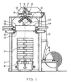
Das in Fig. 1 gezeigte Ausführungsbeispiel zur Durchführung des Verfahrens umfaßt ein Vorrichtungsgestell 1, zwischen dessen vertikalen Ständern eine Fahrbahn 2 zum Zu- und Abfördern von Stückgutstapeln 3, die jeweils aus einer Mehrzahl von übereinander angeordneten Stückgutteilen gebildet sind, angeordnet ist. An dem Vorrichtungsgestell 1 ist eine Rolle 4 gelagert, auf der eine Schlauchfolie 5 aufgewickelt ist. Dabei sind die Seitenränder der Schlauchfolie 5 im aufgewickelten Zustand eingefaltet. Die Schlauchfolie 5 wird über Umlenkrollen 6 und Abzugsrollen 7 einer Einfädeleinrichtung zugeführt, die vertikal bewegliche Leitelemente 8 aufweist. Die Vorrichtung umfaßt weiterhin eine Trenneinrichtung 9 sowie eine Schweißeinrichtung 10.The embodiment shown in Fig. 1 for performing the method comprises a
Unterhalb der Leitelemente 8 sind in bekannter Weise auf beiden Seiten des Vorrichtungsgestells 1 dachförmig verlaufende Doppelförderbänder 11 angeordnet, deren obere Aufnahmeenden unmittelbar unterhalb der Leitelemente 8 in deren vertikal abgesenkter Stellung befindlich sind.Below the
An den vier Ständern des Vorrichtungsgestells 1 sind jeweils Schlitten 12 in vertikaler bzw. Längsrichtung der zugeführten Schlauchfolie 5 gelagert, an denen jeweils ein Spreizfinger 13 befestigt ist. Die vorliegend über die vier Ständer abgestützten Spreizfinger 13 weisen horizontal verlaufende Bügel 14 auf, die jeweils etwa rechtwinklig zueinander angeordnet sind. Jeder Spreizfinger 13 ist über eine Antriebseinrichtung 15 an einem entsprechenden Ständer des Vorrichtungsgestells 1 abgestützt. Die Antriebseinrichtung 15 ist vorliegend aus einem hydraulischen Zylinder gebildet, wobei sämtliche Längsachsen der hydraulischen Zylinder in etwa auf den Mittelpunkt des Vorrichtungsgestells ausgerichtet sind und in einer etwa horizontalen Ebene liegen. In Zuführrichtung der Schlauchfolie 5 vor den Spreizfingem 13 ist außen eine Antriebsrolle 16 auf dem Schlitten 12 montiert, die in Horizontal- bzw. Querrichtung bewegbar ist. Bei dem gezeigten Ausführungsbeispiel erstreckt sich die Längsachse der Antriebsrolle 16 parallel zu einer jeweiligen Seitenfläche des Stückgutstapels 3.On the four uprights of the
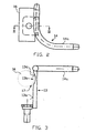
Die Fig. 2 und 3 zeigen einen Spreizfinger 13 sowie einen diesem zugeordneten Bügel 14 im Detail. Das dargestellte Ausführungsbeispiel eines Spreizfingers 13 hat eine ebene äußere Anlagefläche 13a, die sich zwischen dem Bügel 14 und dem befestigungsseitigen Ende des Spreizfingers 13 an dessen Außenseite erstreckt. Unterhalb des Bügels 14 ist an der Anlagefläche 13a eine konkave Mulde 13b gebildet, die durch eine Zylindermantelfläche 13c begrenzt ist. Die konkave Mulde 13b erstreckt sich parallel zu der axialen Richtung der Antriebsrolle 16, die in Fig. 3 mit gestrichelter Linie angedeutet ist. Dabei ist das Verhältnis der Krümmungsradien der Antriebsrolle 16 einerseits und der Zylindermantelfläche 13c andererseits derart gewählt, daß in dem in Fig. 3 angedeuteten eingefahrenen Zustand der Antriebsrolle in die Mulde 13b zwischen der Antriebsrolle 16 und der Mulde 13b ein ringsegmentförmiger Spalt 17 gebildet ist. Dementsprechend ist der Radius der Antriebsrolle ein wenig kleiner als der Krümmungsradius der Zylindermantelfläche 13c. Bei dem gezeigten Ausführungsbeispiel kann in dem ringförmigen Spalt 17 eine Umschlingung der Antriebsrolle 16 durch die Schlauchfolie 5 von ca. 60° erzielt werden.2 and 3 show a Spreizfinger 13 and a
Bei dem in den Fig. 2 und 3 gezeigten Ausführungsbeispiel ist die Anlagefläche 13a in Zuführrichtung der Schlauchfolie 5 unterhalb eines geraden Endabschnitts 14a des Bügels 14 angeordnet. Die Ausbildung der Anlagefläche 13a und die Anordnung derselben relativ zu dem Bügel 14 steht jedoch im Belieben des Fachmannes. Wesentlich ist lediglich, daß die Antriebsrolle 16 und die Mulde 13b derart zueinander ausgerichtet sind, daß die Schlauchfolie 5 bei in die Mulde 13b eingefahrener Antriebsrolle 16 zumindest linienförmig, vorzugsweise entlang der Längsachse der Antriebsrolle zwischen der Mulde 13b und der Antriebsrolle 16 geklemmt ist.In the embodiment shown in FIGS. 2 and 3, the
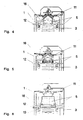
Der Verfahrensablauf zum Umhüllen eines Stückgutstapels 3 wird nachfolgend insbe sondere unter Bezugnahme auf die Fig. 4-6 erläutert:The procedure for wrapping a
Die flach liegende Schlauchfolie 5 wird in an sich bekannter Weise durch die Abzugsrollen 7 über die Leitelemente 8 eingefädelt. Am unteren Ende der Leitelemente wird jeder eingefaltete Rand der Schlauchfolie 5 zwischen ein Doppelförderband 11 geleitet, um den Schlauch zu öffnen (Fig. 4). Nachdem das untere Ende der Schlauchfolie 5 ein Stück aus den Dopelförderbändern 11 herausgelaufen ist, werden die Abzugsrollen 7 sowie die Doppelförderbänder 11 gestoppt und die Spreizfinger 13 werden in das Schlauchende eingefahren. Wenn die Spreizfinger 13 eine vorbestimmte Position erreicht haben, werden die Antriebsrollen 16 an die Spreizfinger 13 herangefahren. Dabei fährt ein Teil der Umfangsfläche der jeweiligen Antriebsrolle 16 in die Mulde 13b des zugeordneten Spreizfingers 13 ein und klemmt die Schlauchfolie 5 in dem Spalt 17. Danach werden die Antriebsrollen 16 zusammen mit den Abzugsrollen 7 und den Doppelförderbändern 11 in Betrieb gesetzt, bis eine vorbestimmte Länge an Schlauchfolie 5 balgenartig, d.h. mäandrierend über die Spreizfinger 13 gelegt ist (Fig. 5). Jetzt werden die Trenn- und Schweißeinrichtungen 9 und 10 betätigt, um das abgezogene, unterhalb der Trenn- und Schweißeinrichtungen 9, 11 befindliche Teilstück der Schlauchfolie 5 zu einer oben verschlossenen Schlauchhaube 18 vorbestimmter Länge zu bilden. Danach werden die Doppelförderbänder 11 erneut angetrieben und in bekannter Weise verschwenkt, um den restlichen Teil der gebildeten Schlauchhaube 18 freizugeben, der ggf. durch erneutes Anfahren der Antriebsrollen 16 straff über die Bügel 14 gespannt werden kann.The flat
Ausgehend von dieser Ausgangslage werden die Spreizfinger 13 in Querrichtung auseinandergefahren. Bei dem gezeigten Ausführungsbeispiel erfolgt die Bewegung der Spreizfinger 13 diagonal gegenüber der Grundfläche des Stückgutstapels 3. Bei diesem Querdehnen drücken die Antriebsrollen 16 unter Zwischenlage der Schlauchhaube 18 weiterhin gegen die Spreizfinger 13, so daß ein ungewolltes Herausziehen der gerefften Schlauchhaube 8 vermieden wird. Bei der Querbewegung der Spreizfinger 13 wird die Schlauchhaube 8 um mindestens 50 %, vorzugsweise um mindestens 80 % gegenüber der ungedehnten Schlauchhaube gedehnt. Dabei ist insbesondere eine Querdehnung von insgesamt 50 % mit einem elastischen Anteil der Dehnung von mindestens 20 % zu bevorzugen, was nachfolgend noch erläutert wird.Starting from this initial position, the spreading
Nach Beendigung der Querdehnung ist ein Zustand erreicht, wie er aus Fig. 1 ersichtlich ist. Die Spreizfinger 13 werden zusammen mit den Antriebsrollen 16 über die jeweiligen Schlitten 12 gleichmäßig in Richtung auf den Stückgutstapel 3 zubewegt. Dabei legt sich das obere verschlossene Ende der durch Verschweißen gebildeten Schlauchhaube 18 zunächst auf die Oberfläche des Stückgutstapels 3 und umschließt aufgrund der Querdehnung die äußeren oberen Kanten des Stückgutstapels beim weiteren Absenken der Schlitten 12 bündig.After completion of the transverse strain, a state is reached, as can be seen in FIG. The spreading
Das Anlegen der Schlauchhaube 8 an die Seiten des Stückgutstapels 3 erfolgt bei einer elastischen Längsdehnung von mindestens 50 %, gegenüber der ungedehnten Schlauchhaube 18. Hierzu werden die Antriebsrollen 16 mit einem vorbestimmten Dreh- bzw. Bremsmoment angesteuert, das ein Herausgleiten des gerefften Schlauchhaubenmaterials durch den Spalt 17 erst nach Überschreiten der gewünschten elastischen Längsdehnung ermöglicht. Im Gegensatz zu dem vorbekannten Haubenstretchen, bei dem eine Folie verwendet wird, deren elastische Dehnung allerhöchstens in der Größenordnung der plastischen Dehnung liegt und die daher beim Anlegen an den Stückgutstapel insbesondere zu einer plastischen Verformung entlang der durch die einzelnen Stückgutteile gebildeten Kontur neigt und die Stückgutlagen einzeln umschließt, kann die elastische Schlauchfolie 5 beim Überziehen über den Stückgutstapel 3 wie ein Gummiband über die einzelnen Lagen der Stückgutteile wandern. Die Schlauchhaube 18 liegt demnach lediglich an der Oberkante des Stückgutstapels 3 fest. Die gleichmäßige, durch die Antriebsrolle 16 gesteuerte Abzugskraft in Längsrichtung führt zu einer gleichmäßigen Belastung des Stückgutstapels 3, die bei einer Entlüftung von Stückgutteilen während des Überziehens der Schlauchhaube 18 die gewünschte Formbeständigkeit der zu bildenden Verpackungseinheit sicherstellt und insbesondere gewährleistet, daß die Oberseite des Stückgutstapels 3 auch bei stärkeren Entlüftungserscheinungen im wesentlichen parallel zu der durch eine Palette gebildete Unterseite der Verpackungseinheit verläuft.The application of the
Auf dem Weg der Schlitten 12 nach unten wird die zunächst gereffte Schlauchhaube 18 von den Spreizfingem 13 gezogen und unter elastischen Längsdehnung an den Stückgutstapel 3 gelegt. Am Ende dieser Abwärtsbewegung befinden sich die Spreizfinger 13 in etwa auf der Höhe der Unterkante des Stückgutstapels 3. Der elastische Anteil der Querdehnung der Schlauchhaube 18 kann nunmehr durch Freigeben der restlichen Länge der Schlauchhaube 18 entspannt werden, wobei die Spreizfinger 13 hierzu relativ zu dem Stückgutstapel 3 vorzugsweise derart angeordnet sind, daß sich die nach innen entspannende Schlauchhaube 18 zumindest teilweise unter die Palette zieht. Bei einer derartigen Verfahrensführung ist bei einer Einstellung der Querdehnung darauf zu achten, daß sich die Schlauchhaube 18 derart unter die Palette zieht, daß die elastische, über dem Stückgutstapel gezogene Schlauchhaube 18 nicht aufgrund der elastischen Längsdehnung nach oben gezogen wird. Demnach ist es zu bevorzugen, vor dem Überziehen der Schlauchhaube 18 derselben eine elastische Querdehnung von mindstens 50% und besonders bevorzugt von mindestens 80 % aufzuprägen. Alternativ oder zusätzlich kann die Unterkante der Schlauchhaube 18 an der Palette befestigt werden, beispielsweise durch Klammern, was jedoch ein späteres Entfemen der Schlauchhaube 18 zum Freilegen der Stückgutteile problematisch macht. Weiterhin alternativ kann das freie Ende der Schlauchhaube 18 auch im Bereich der Palette mit der Verpackungseinheit verklebt oder verschweißt werden, wobei für eine derartige Verbindung vorzugsweise im Bereich der Palette, insbesondere zwischen der untersten Stückgutlage und der Palette, eine Folie angeordnet sein kann, mit der die übergezogene Schlauchhaube 18 verbunden wird.On the way the
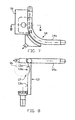
Ein Ausführungsbeispiel für ein Anpreßelement 19 ist in den Figuren 7 und 8 gezeigt. Dabei handelt es sich um ein kreissegmentförmig, den gebogenen Bereich des Bügels 14 umgebendes Element, dessen Krümmungsradius in etwa dem Krümmungsradius des gebogenen Bereiches des Fingers 14 entspricht (Fig. 7). Die dem Finger 14 zugewandte Anspreßfläche des Anspreßelementes 19 ist konkav ausgebildet und weist einen Krümmungsradius auf, der in etwa dem Radius des Querschnitts des Bügels 14 entspricht. Auch hier sind die Radienverhältnisse zwischen Krümmung des Bügels bzw. Radius des Bügelquerschnitts einerseits und dem Krümmungsradius des Anpreßelementes 19 bzw. dem Krümmungsradius der Anpreßfläche derart gewählt, daß die zwischen dem Bügel 14 und dem Anpreßelement 19 gehaltene Folie flächig angedrückt wird. Zum Anpressen und Freigeben der Folie zwischen dem Bügel 14 und dem Anpreßelement 19 ist eine nicht dargestellte Betätigungsvorrichtung vorgesehen, die das Anpreßelement 19 mit einem Winkel von ca. 45° zu der Längsachse der jeweiligen geraden Endabschnitte 14a des Bügels 14 zuführt und vorzugsweise mit einer zentralen Steuereinrichtung verbunden ist, um die gewünschte Längsdehnung zu steuern.An embodiment of a pressing member 19 is shown in Figures 7 and 8. This is a circular segment, the curved portion of the
- 11
- Vorrichtungsgestelldevice stand
- 22
- Fahrbahnroadway
- 33
- Stückgutstapelstack of packaged goods
- 44
- Rollerole
- 55
- Schlauchfolietubular film
- 66
- Umlenkrollenguide rollers
- 77
- Abzugsrollenoff rollers
- 88th
- Leitelementenvanes
- 99
- Trenneinrichtungseparator
- 1010
- SchweizeinrichtungSwitzerland device
- 1111
- DoppelförderbandDouble conveyor belt
- 1212
- Schlittencarriage
- 1313
- Spreizfingerspreading fingers
- 13a13a
- Anlageflächecontact surface
- 13b13b
- Muldetrough
- 13c13c
- ZylindermantelflächeCylinder surface
- 1414
- Bügelhanger
- 14a14a
- gerader Endabschnittstraight end section
- 1515
- Antriebseinrichtungdriving means
- 1616
- Antriebsrollecapstan
- 1717
- Spaltgap
- 1818
- Schlauchhaubetubular hood
- 1919
- Anpreßelementpressing element
Claims (4)
- A method of wrapping a stack of packaged goods (3) formed from a plurality of items of packaged goods disposed one above the other, in which tubular film (5) is drawn off to form a tubular hood, is opened, reefed in a longitudinal direction, separated from the tubular film (5) and sealed, the reefed tubular hood (18) is subsequently stretched in a transverse direction and is then drawn over the stack of packaged goods (3) with longitudinal elongation,
characterised in
that the tubular hood (18) is formed from a highly elastic film (5) which is applied to the stack of packaged goods (3) with an elastic longitudinal elongation of at least 50 % with respect to the unstretched tubular hood (18). - Method according to Claim 1, characterised in that the tubular film (5) is applied to the stack of packaged goods (3) with a longitudinal elongation of at least 80 %, preferably of at least 100 % an especially preferably of at least 150 %, with respect to the unstretched tubular hood (18).
- Method according to Claim 1 or 2, characterised in that the longitudinal elongation is brought about at least partly as the drawing-over the stack of packaged goods (3) takes place.
- Method according to at least one of the preceding Claims, characterised in that the reefed film (5) is stretched in transverse direction by at least 50 %, preferably by 80 % with respect to the unstretched tubular hood (18).
Applications Claiming Priority (2)
| Application Number | Priority Date | Filing Date | Title |
|---|---|---|---|
| DE19859889A DE19859889A1 (en) | 1998-12-23 | 1998-12-23 | Method and device for wrapping a piece of general cargo |
| DE19859889 | 1998-12-23 |
Publications (3)
| Publication Number | Publication Date |
|---|---|
| EP1013549A1 EP1013549A1 (en) | 2000-06-28 |
| EP1013549B1 EP1013549B1 (en) | 2003-04-16 |
| EP1013549B2 true EP1013549B2 (en) | 2007-04-04 |
Family
ID=7892557
Family Applications (1)
| Application Number | Title | Priority Date | Filing Date |
|---|---|---|---|
| EP99125412A Expired - Lifetime EP1013549B2 (en) | 1998-12-23 | 1999-12-20 | Method and device for enveloping a stack of goods |
Country Status (5)
| Country | Link |
|---|---|
| EP (1) | EP1013549B2 (en) |
| AT (1) | ATE237498T1 (en) |
| DE (2) | DE19859889A1 (en) |
| DK (1) | DK1013549T4 (en) |
| ES (1) | ES2195501T3 (en) |
Cited By (2)
| Publication number | Priority date | Publication date | Assignee | Title |
|---|---|---|---|---|
| DE102009022239A1 (en) * | 2009-05-22 | 2010-11-25 | Maschinenfabrik Möllers Gmbh | Method and device for producing a packaging unit |
| DE102011010126A1 (en) * | 2011-02-02 | 2012-08-02 | Maschinenfabrik Möllers Gmbh | Method for producing a palletless packaging unit |
Families Citing this family (13)
| Publication number | Priority date | Publication date | Assignee | Title |
|---|---|---|---|---|
| DE10103261A1 (en) * | 2001-01-25 | 2002-08-14 | Msk Verpackung Syst Gmbh | Method of covering a flat hose |
| DE50203177D1 (en) * | 2001-07-11 | 2005-06-30 | Moellers Maschf Gmbh | Device for covering a stretch film hood over a stack of goods |
| FR2835236B1 (en) * | 2002-01-28 | 2004-05-28 | Thimon | METHOD AND DEVICE FOR PLACING A STRETCHED SHEATH ON A PALLETIZED LOAD |
| DE50308120D1 (en) * | 2002-04-19 | 2007-10-18 | Msk Verpackung Syst Gmbh | DEVICE AND METHOD FOR TURNING PIECE OR PACKING |
| EP2036818B1 (en) | 2007-11-30 | 2011-05-25 | Maschinenfabrik Möllers GmbH | Method for manufacturing a palletless packaging unit |
| DE202007018783U1 (en) | 2007-11-30 | 2009-05-20 | Maschinenfabrik Möllers Gmbh | Palletless packaging unit |
| DE102009020454B3 (en) | 2009-05-08 | 2010-10-28 | Maschinenfabrik Möllers Gmbh | Method and device for producing a palletless packaging unit and palletless packaging unit |
| DE102009024002B3 (en) * | 2009-06-05 | 2011-03-17 | Maschinenfabrik Möllers Gmbh | Device and method for producing a packaging unit |
| WO2012072092A1 (en) | 2010-11-30 | 2012-06-07 | Maschinenfabrik Möllers Gmbh | Apparatus and method for producing a packaging unit |
| DE102011013974A1 (en) | 2011-03-15 | 2012-09-20 | Maschinenfabrik Möllers Gmbh | Method for producing a packaging unit |
| DE102011103366B3 (en) * | 2011-06-03 | 2012-09-20 | Maschinenfabrik Möllers Gmbh | Method and device for producing a palletless packaging unit |
| DE102012024176B4 (en) * | 2012-12-10 | 2019-02-07 | Beumer Gmbh & Co. Kg | Device for coating a tubular packaging film and reef element |
| US11492155B2 (en) * | 2020-05-14 | 2022-11-08 | Signode Industrial Group Llc | Stretch-hood machine |
Family Cites Families (8)
| Publication number | Priority date | Publication date | Assignee | Title |
|---|---|---|---|---|
| FR2230549A1 (en) * | 1973-05-23 | 1974-12-20 | Applic Thermiques | Machine for packing an object in a plastic sleeve - compresses sleeve into bellows form before passing object through |
| EP0081328A3 (en) | 1981-12-07 | 1984-03-28 | Kenneth Stephen Eddin Orpen | Improvements in packaging film dispensers |
| US4499706A (en) * | 1983-05-19 | 1985-02-19 | Exxon Research & Engineering Co. | Pass through stretch wrapping process |
| DE3873583D1 (en) * | 1987-03-11 | 1992-09-17 | Lachenmeier Kurt Aps | METHOD AND DEVICE FOR PACKAGING ITEMS WITH A PLASTIC PLASTIC FILM. |
| DE58900904D1 (en) | 1988-06-03 | 1992-04-09 | Beumer Maschf Bernhard | METHOD AND DEVICE FOR COVERING PIECES OF GOODS, IN PARTICULAR STACKS OF GOODS, WITH A STRETCH FILM HOOD. |
| DE9001319U1 (en) * | 1990-02-06 | 1990-04-12 | Develog, Reiner Hannen & Cie, Corgemont, Ch | |
| FR2662926A1 (en) * | 1990-06-06 | 1991-12-13 | Moulinex Sa | ELECTRIC KETTLE. |
| PL202384B1 (en) * | 1998-12-18 | 2009-06-30 | Nordfolien Gmbh | Method of wrapping a stack of single objects with sleeve-shaped plastic film and sleeve-shaped plastic film therefor |
-
1998
- 1998-12-23 DE DE19859889A patent/DE19859889A1/en not_active Ceased
-
1999
- 1999-12-20 AT AT99125412T patent/ATE237498T1/en not_active IP Right Cessation
- 1999-12-20 ES ES99125412T patent/ES2195501T3/en not_active Expired - Lifetime
- 1999-12-20 EP EP99125412A patent/EP1013549B2/en not_active Expired - Lifetime
- 1999-12-20 DK DK99125412T patent/DK1013549T4/en active
- 1999-12-20 DE DE59905061T patent/DE59905061D1/en not_active Expired - Lifetime
Cited By (3)
| Publication number | Priority date | Publication date | Assignee | Title |
|---|---|---|---|---|
| DE102009022239A1 (en) * | 2009-05-22 | 2010-11-25 | Maschinenfabrik Möllers Gmbh | Method and device for producing a packaging unit |
| DE102011010126A1 (en) * | 2011-02-02 | 2012-08-02 | Maschinenfabrik Möllers Gmbh | Method for producing a palletless packaging unit |
| DE102011010126B4 (en) * | 2011-02-02 | 2013-01-17 | Maschinenfabrik Möllers Gmbh | Method for producing a palletless packaging unit |
Also Published As
| Publication number | Publication date |
|---|---|
| DK1013549T4 (en) | 2007-05-14 |
| EP1013549A1 (en) | 2000-06-28 |
| DK1013549T3 (en) | 2003-06-23 |
| DE19859889A1 (en) | 2000-06-29 |
| EP1013549B1 (en) | 2003-04-16 |
| ATE237498T1 (en) | 2003-05-15 |
| ES2195501T3 (en) | 2003-12-01 |
| DE59905061D1 (en) | 2003-05-22 |
Similar Documents
| Publication | Publication Date | Title |
|---|---|---|
| EP1013549B2 (en) | Method and device for enveloping a stack of goods | |
| DE3918311C2 (en) | Method and device for wrapping piece goods, in particular piece goods stacks, with a stretch film hood | |
| DE2324293C3 (en) | Device for tying a bale or the like | |
| EP2116470B1 (en) | Method for applying flat straps around packages and device for carrying out the method | |
| DE4103384A1 (en) | Machine for wrapping goods in elastic film - has stretching frame which maintains tension of film as goods are wrapped | |
| WO2009115314A1 (en) | Packaging device and packaging method | |
| DE4401818C2 (en) | Clamping device, in particular for clamping a sheet package when changing stacks in stacking devices for sheets of paper or cardboard | |
| DE2548786B2 (en) | Device for producing a tight band around a packaging item | |
| EP0681958B1 (en) | Device for strapping especially compressible goods such as sheets of corrugated cardboard or the like | |
| EP0564971B1 (en) | Device and method for making a stack of articles | |
| WO2004002829A1 (en) | Strapping device | |
| DE1963531A1 (en) | Packaging method and device therefor | |
| EP2478757B1 (en) | Baling press | |
| DE2619422C2 (en) | Foil packing machine | |
| EP0235378B1 (en) | Machine for pressing and tying bales | |
| EP1275582B1 (en) | Apparatus for wrapping a stack of products in a stretchable foil cover | |
| DE3019428A1 (en) | CLAMPING DEVICE FOR PLATE PRESSES, ESPECIALLY VOLCANIZING PRESSES | |
| EP2653393B1 (en) | Method and device for strapping a stack of flat laminar products | |
| EP1350720B1 (en) | Method and apparatus for packaging a stack of articles | |
| EP1048565B1 (en) | Method and device for packaging objects in a film-hood | |
| DE19524456C2 (en) | Method and device for strapping compressible packages | |
| DE2213758C3 (en) | Bundling device for packaging piece goods | |
| DD216211A1 (en) | BINDING FIELD FOR BAND FOAMING STRIPE MATERIAL | |
| EP1048566A1 (en) | Method and device for packaging objects in a film-hood | |
| DE2605858A1 (en) | METHOD AND DEVICE FOR TIEING UP PACKAGING UNITS |
Legal Events
| Date | Code | Title | Description |
|---|---|---|---|
| PUAI | Public reference made under article 153(3) epc to a published international application that has entered the european phase |
Free format text: ORIGINAL CODE: 0009012 |
|
| AK | Designated contracting states |
Kind code of ref document: A1 Designated state(s): AT BE CH CY DE DK ES FI FR GB GR IE IT LI LU MC NL PT SE |
|
| AX | Request for extension of the european patent |
Free format text: AL;LT;LV;MK;RO;SI |
|
| 17P | Request for examination filed |
Effective date: 20000608 |
|
| AKX | Designation fees paid |
Free format text: AT BE CH CY DE DK ES FI FR GB GR IE IT LI LU MC NL PT SE |
|
| GRAH | Despatch of communication of intention to grant a patent |
Free format text: ORIGINAL CODE: EPIDOS IGRA |
|
| GRAH | Despatch of communication of intention to grant a patent |
Free format text: ORIGINAL CODE: EPIDOS IGRA |
|
| GRAA | (expected) grant |
Free format text: ORIGINAL CODE: 0009210 |
|
| AK | Designated contracting states |
Designated state(s): AT BE CH CY DE DK ES FI FR GB GR IE IT LI LU MC NL PT SE |
|
| PG25 | Lapsed in a contracting state [announced via postgrant information from national office to epo] |
Ref country code: IT Free format text: LAPSE BECAUSE OF FAILURE TO SUBMIT A TRANSLATION OF THE DESCRIPTION OR TO PAY THE FEE WITHIN THE PRESCRIBED TIME-LIMIT;WARNING: LAPSES OF ITALIAN PATENTS WITH EFFECTIVE DATE BEFORE 2007 MAY HAVE OCCURRED AT ANY TIME BEFORE 2007. THE CORRECT EFFECTIVE DATE MAY BE DIFFERENT FROM THE ONE RECORDED. Effective date: 20030416 Ref country code: IE Free format text: LAPSE BECAUSE OF NON-PAYMENT OF DUE FEES Effective date: 20030416 Ref country code: FI Free format text: LAPSE BECAUSE OF FAILURE TO SUBMIT A TRANSLATION OF THE DESCRIPTION OR TO PAY THE FEE WITHIN THE PRESCRIBED TIME-LIMIT Effective date: 20030416 |
|
| REG | Reference to a national code |
Ref country code: GB Ref legal event code: FG4D Free format text: NOT ENGLISH |
|
| REG | Reference to a national code |
Ref country code: CH Ref legal event code: EP |
|
| REF | Corresponds to: |
Ref document number: 59905061 Country of ref document: DE Date of ref document: 20030522 Kind code of ref document: P |
|
| REG | Reference to a national code |
Ref country code: IE Ref legal event code: FG4D Free format text: GERMAN |
|
| REG | Reference to a national code |
Ref country code: DK Ref legal event code: T3 |
|
| GBT | Gb: translation of ep patent filed (gb section 77(6)(a)/1977) | ||
| PG25 | Lapsed in a contracting state [announced via postgrant information from national office to epo] |
Ref country code: SE Free format text: LAPSE BECAUSE OF FAILURE TO SUBMIT A TRANSLATION OF THE DESCRIPTION OR TO PAY THE FEE WITHIN THE PRESCRIBED TIME-LIMIT Effective date: 20030716 Ref country code: PT Free format text: LAPSE BECAUSE OF FAILURE TO SUBMIT A TRANSLATION OF THE DESCRIPTION OR TO PAY THE FEE WITHIN THE PRESCRIBED TIME-LIMIT Effective date: 20030716 Ref country code: GR Free format text: LAPSE BECAUSE OF FAILURE TO SUBMIT A TRANSLATION OF THE DESCRIPTION OR TO PAY THE FEE WITHIN THE PRESCRIBED TIME-LIMIT Effective date: 20030716 |
|
| REG | Reference to a national code |
Ref country code: IE Ref legal event code: FD4D Ref document number: 1013549E Country of ref document: IE |
|
| PG25 | Lapsed in a contracting state [announced via postgrant information from national office to epo] |
Ref country code: LU Free format text: LAPSE BECAUSE OF NON-PAYMENT OF DUE FEES Effective date: 20031220 Ref country code: CY Free format text: LAPSE BECAUSE OF FAILURE TO SUBMIT A TRANSLATION OF THE DESCRIPTION OR TO PAY THE FEE WITHIN THE PRESCRIBED TIME-LIMIT Effective date: 20031220 |
|
| PG25 | Lapsed in a contracting state [announced via postgrant information from national office to epo] |
Ref country code: MC Free format text: LAPSE BECAUSE OF NON-PAYMENT OF DUE FEES Effective date: 20031231 Ref country code: LI Free format text: LAPSE BECAUSE OF NON-PAYMENT OF DUE FEES Effective date: 20031231 Ref country code: CH Free format text: LAPSE BECAUSE OF NON-PAYMENT OF DUE FEES Effective date: 20031231 |
|
| PLBQ | Unpublished change to opponent data |
Free format text: ORIGINAL CODE: EPIDOS OPPO |
|
| PLBI | Opposition filed |
Free format text: ORIGINAL CODE: 0009260 |
|
| PLAX | Notice of opposition and request to file observation + time limit sent |
Free format text: ORIGINAL CODE: EPIDOSNOBS2 |
|
| ET | Fr: translation filed | ||
| 26 | Opposition filed |
Opponent name: BEUMER MASCHINENFABRIK GMBH & CO. KG Effective date: 20040114 |
|
| NLR1 | Nl: opposition has been filed with the epo |
Opponent name: BEUMER MASCHINENFABRIK GMBH & CO. KG |
|
| PLBB | Reply of patent proprietor to notice(s) of opposition received |
Free format text: ORIGINAL CODE: EPIDOSNOBS3 |
|
| REG | Reference to a national code |
Ref country code: CH Ref legal event code: PL |
|
| PGFP | Annual fee paid to national office [announced via postgrant information from national office to epo] |
Ref country code: GB Payment date: 20041129 Year of fee payment: 6 |
|
| PGFP | Annual fee paid to national office [announced via postgrant information from national office to epo] |
Ref country code: ES Payment date: 20041210 Year of fee payment: 6 |
|
| PGFP | Annual fee paid to national office [announced via postgrant information from national office to epo] |
Ref country code: FR Payment date: 20041215 Year of fee payment: 6 |
|
| PGFP | Annual fee paid to national office [announced via postgrant information from national office to epo] |
Ref country code: AT Payment date: 20041216 Year of fee payment: 6 |
|
| PGFP | Annual fee paid to national office [announced via postgrant information from national office to epo] |
Ref country code: NL Payment date: 20041217 Year of fee payment: 6 |
|
| PGFP | Annual fee paid to national office [announced via postgrant information from national office to epo] |
Ref country code: BE Payment date: 20041220 Year of fee payment: 6 |
|
| PLAY | Examination report in opposition despatched + time limit |
Free format text: ORIGINAL CODE: EPIDOSNORE2 |
|
| PLBC | Reply to examination report in opposition received |
Free format text: ORIGINAL CODE: EPIDOSNORE3 |
|
| PG25 | Lapsed in a contracting state [announced via postgrant information from national office to epo] |
Ref country code: GB Free format text: LAPSE BECAUSE OF NON-PAYMENT OF DUE FEES Effective date: 20051220 Ref country code: AT Free format text: LAPSE BECAUSE OF NON-PAYMENT OF DUE FEES Effective date: 20051220 |
|
| PG25 | Lapsed in a contracting state [announced via postgrant information from national office to epo] |
Ref country code: ES Free format text: LAPSE BECAUSE OF NON-PAYMENT OF DUE FEES Effective date: 20051221 |
|
| PG25 | Lapsed in a contracting state [announced via postgrant information from national office to epo] |
Ref country code: BE Free format text: LAPSE BECAUSE OF NON-PAYMENT OF DUE FEES Effective date: 20051231 |
|
| PG25 | Lapsed in a contracting state [announced via postgrant information from national office to epo] |
Ref country code: NL Free format text: LAPSE BECAUSE OF NON-PAYMENT OF DUE FEES Effective date: 20060701 |
|
| GBPC | Gb: european patent ceased through non-payment of renewal fee |
Effective date: 20051220 |
|
| PG25 | Lapsed in a contracting state [announced via postgrant information from national office to epo] |
Ref country code: FR Free format text: LAPSE BECAUSE OF NON-PAYMENT OF DUE FEES Effective date: 20060831 |
|
| NLV4 | Nl: lapsed or anulled due to non-payment of the annual fee |
Effective date: 20060701 |
|
| REG | Reference to a national code |
Ref country code: FR Ref legal event code: ST Effective date: 20060831 |
|
| PUAH | Patent maintained in amended form |
Free format text: ORIGINAL CODE: 0009272 |
|
| STAA | Information on the status of an ep patent application or granted ep patent |
Free format text: STATUS: PATENT MAINTAINED AS AMENDED |
|
| REG | Reference to a national code |
Ref country code: ES Ref legal event code: FD2A Effective date: 20051221 |
|
| 27A | Patent maintained in amended form |
Effective date: 20070404 |
|
| AK | Designated contracting states |
Kind code of ref document: B2 Designated state(s): AT BE CH CY DE DK ES FI FR GB GR IE IT LI LU MC NL PT SE |
|
| REG | Reference to a national code |
Ref country code: DK Ref legal event code: T4 |
|
| REG | Reference to a national code |
Ref country code: ES Ref legal event code: FD2A Effective date: 20051221 |
|
| EN | Fr: translation not filed | ||
| BERE | Be: lapsed |
Owner name: MASCHINENFABRIK *MOLLERS G.M.B.H. U. CO. Effective date: 20051231 |
|
| PGFP | Annual fee paid to national office [announced via postgrant information from national office to epo] |
Ref country code: DK Payment date: 20181219 Year of fee payment: 20 |
|
| PGFP | Annual fee paid to national office [announced via postgrant information from national office to epo] |
Ref country code: DE Payment date: 20181221 Year of fee payment: 20 |
|
| REG | Reference to a national code |
Ref country code: DE Ref legal event code: R071 Ref document number: 59905061 Country of ref document: DE |
|
| REG | Reference to a national code |
Ref country code: DK Ref legal event code: EUP Effective date: 20191220 |