EP1013546B1 - Raketennutzlastverkleidung und ihr Öffnungsverfahren - Google Patents
Raketennutzlastverkleidung und ihr Öffnungsverfahren Download PDFInfo
- Publication number
- EP1013546B1 EP1013546B1 EP99125840A EP99125840A EP1013546B1 EP 1013546 B1 EP1013546 B1 EP 1013546B1 EP 99125840 A EP99125840 A EP 99125840A EP 99125840 A EP99125840 A EP 99125840A EP 1013546 B1 EP1013546 B1 EP 1013546B1
- Authority
- EP
- European Patent Office
- Prior art keywords
- side wall
- fairing
- joint member
- rocket
- wall segments
- Prior art date
- Legal status (The legal status is an assumption and is not a legal conclusion. Google has not performed a legal analysis and makes no representation as to the accuracy of the status listed.)
- Expired - Lifetime
Links
- 238000000034 method Methods 0.000 title claims description 16
- 230000007246 mechanism Effects 0.000 claims description 70
- 230000004048 modification Effects 0.000 description 7
- 238000012986 modification Methods 0.000 description 7
- 230000033001 locomotion Effects 0.000 description 4
- 238000010276 construction Methods 0.000 description 3
- 238000006243 chemical reaction Methods 0.000 description 2
- 230000006835 compression Effects 0.000 description 2
- 238000007906 compression Methods 0.000 description 2
- 239000000356 contaminant Substances 0.000 description 2
- 230000009977 dual effect Effects 0.000 description 2
- 230000000694 effects Effects 0.000 description 2
- 238000007796 conventional method Methods 0.000 description 1
- 238000006073 displacement reaction Methods 0.000 description 1
- 230000007613 environmental effect Effects 0.000 description 1
- 239000002360 explosive Substances 0.000 description 1
- 238000010438 heat treatment Methods 0.000 description 1
- 230000007257 malfunction Effects 0.000 description 1
- 239000002184 metal Substances 0.000 description 1
- 239000000523 sample Substances 0.000 description 1
- 238000007789 sealing Methods 0.000 description 1
Images


Classifications
-
- B—PERFORMING OPERATIONS; TRANSPORTING
- B64—AIRCRAFT; AVIATION; COSMONAUTICS
- B64G—COSMONAUTICS; VEHICLES OR EQUIPMENT THEREFOR
- B64G1/00—Cosmonautic vehicles
- B64G1/22—Parts of, or equipment specially adapted for fitting in or to, cosmonautic vehicles
- B64G1/64—Systems for coupling or separating cosmonautic vehicles or parts thereof, e.g. docking arrangements
- B64G1/645—Separators
-
- B—PERFORMING OPERATIONS; TRANSPORTING
- B64—AIRCRAFT; AVIATION; COSMONAUTICS
- B64G—COSMONAUTICS; VEHICLES OR EQUIPMENT THEREFOR
- B64G1/00—Cosmonautic vehicles
- B64G1/002—Launch systems
-
- B—PERFORMING OPERATIONS; TRANSPORTING
- B64—AIRCRAFT; AVIATION; COSMONAUTICS
- B64G—COSMONAUTICS; VEHICLES OR EQUIPMENT THEREFOR
- B64G1/00—Cosmonautic vehicles
- B64G1/22—Parts of, or equipment specially adapted for fitting in or to, cosmonautic vehicles
- B64G1/228—Damping of high-frequency vibration effects on spacecraft elements, e.g. by using acoustic vibration dampers
-
- B—PERFORMING OPERATIONS; TRANSPORTING
- B64—AIRCRAFT; AVIATION; COSMONAUTICS
- B64G—COSMONAUTICS; VEHICLES OR EQUIPMENT THEREFOR
- B64G1/00—Cosmonautic vehicles
- B64G1/22—Parts of, or equipment specially adapted for fitting in or to, cosmonautic vehicles
- B64G1/64—Systems for coupling or separating cosmonautic vehicles or parts thereof, e.g. docking arrangements
- B64G1/641—Interstage or payload connectors
Definitions
- the present invention relates to a rocket fairing for use with a rocket for simultaneously launching a plurality of satellites, and a method of opening the rocket fairing.
- tellites Two artificial satellites (hereinafter referred to simply as “satellites”) are mounted on the rocket body (sometimes, referred to simply as “body”) of a rocket and the two satellites are launched simultaneously to launch the satellites efficiently.
- the rocket fairing 6 is attached to a forward section 11 of a rocket body 1 included in a rocket.
- the rocket fairing 6 defines two storage spaces, i.e., a first storage space 4 and a second storage space 5.
- the rocket fairing 6 has a first support structure 7 and a second support structure 8 respectively for supporting a first satellite 2 and a second satellite 3, and a first shell 9 and a second shell 10 respectively surrounding the satellites 2 and 3.
- the satellites 2 and 3 are stored in the storage spaces 4 and 5 formed in the fairing 6 and are supported by the support structures 7 and 8 disposed on the side of the rocket body 1 relative to the satellites 2 and 3, respectively.
- Fig. 15 is an exploded front elevation of the fairing 6 shown in Fig. 14.
- the fairing 6 can be divided into a plurality of components 12 to 15.
- the first component 12 has the frustum-shaped first support structure 7 and a cylindrical side wall 16.
- the first support structure 7 is fitted in the side wall 16.
- the outer surface of an end portion of the first support structure 7 on the fairing-base side is continuous with the outer surface of an end portion of the side wall 16 on the fairing-base side.
- the first support structure 7, i.e., a component of the component 12 is also a component of the forward section 11 of the body 1.
- the first component 12 is attached to the forward section 11 of the body 1.
- the second component 13 has the frustum-shaped second support structure 8 and a cylindrical side wall 17.
- the second support structure 8 is continuous with the forward end of the side wall 17 on the fairing-forward side and is tapered away from the side wall 17.
- the other end, i.e., the base end, of the side wall 17 of the second component 13 on the fairing-base side is connected detachably to the forward end of the side wall 16 of the first component 12 on the fairing-forward side.
- the components 12 and 13 define the first storage space 4.
- the side walls 16 and 17 form the first shell 9 surrounding the first satellite 2 stored in the first storage space 4.
- the third component 14 and the fourth component 15 form the second shell 10 for covering the second satellite 3.
- the components 14 and 15 have semicylindrical side wall segments 18 and 19, and semiconic segments 20 and 21, respectively.
- the components 14 and 15 can detachably be joined together.
- the second shell 10 having a closed nose and the shape of a tapered shell is formed when the components 14 and 15 are joined together.
- the second shell 10 is put on the second component 13 with the base ends of the semicylindrical side wall segments 18 and 19 on the fairing-base side detachably connected to the forward end of the side wall 17 of the second component 13 on the fairing-forward side.
- the second support structure 8 of the second component 13 When the second shell 10 is connected to the second component 13, the second support structure 8 of the second component 13 is received in a space defined by the cylindrical side wall formed by joining together the semicylindrical side wall segments 18 and 19.
- the components 14 and 15 and the support structure 8 define the second storage space 5.
- the semicylindrical side wall segments 18 and 19 of the components 14 and 15 form the second shell 10 surrounding the satellite 3.
- the storage spaces 4 and 5 respectively containing the satellites 2 and 3 are opened, the satellites 2 and 3 are disconnected from the support structures 7 and 8, and the satellites 2 and 3 are released into space. More specifically, the components 14 and 15 are unfastened from each other and from the second component 13, the second shell 10 is split by a parting plane including the longitudinal axis of the fairing 6, i.e., a longitudinal parting plane, and the components 14 and 15 are moved away from the satellite 3 to open the storage space 5, and then the satellite 3 is disconnected from the support structure 8 and is released into space.
- the second component 13 is disconnected and separated from the first component 12 to split the side wall 9 along a plane perpendicular to the longitudinal axis of the fairing 6, the second component 13 is moved away from the satellite 2 to open the storage space 4, and then the satellite is disconnected from the support structure 7 and is released into space.
- the first storage space 4 formed on the fairing-base side to store the first satellite 2 is opened by splitting the side wall 9 by a parting plane perpendicular to the longitudinal axis of the fairing 6.
- the side wall 16 forming a portion of the side wall 9 and surrounding a portion of the first satellite 2 on the fairing-base side is held on the forward section 11 of the rocket body 1.
- an error in a direction in which the first satellite 2 is released i.e., the difference between a direction in which the first satellite 2 is released and the longitudinal axis of the fairing 6, and the tilting of the first satellite occur.
- the portion of the first satellite 2 on the fairing-base side is formed in a cylindrical shape conforming to the shape of the side wall 16, it is possible that the side wall 16 interferes with the portion of the first satellite 2 on the fairing-base side due to the deviation of the direction of movement of the first satellite 2 from the correct direction and the tilting of the first satellite when the first satellite 2 is released.
- an available region 27 available for receiving the first satellite 2 becomes small; that is, the size of the first satellite 2 must be reduced. Therefore, while a portion of an available region 28 available for receiving the second satellite 3 on the fairing-base side may be cylindrical, a portion of the available region 27 available for receiving the first satellite 2 on the fairing-base side must be tapered. Consequently, a cylindrical region of the same diameter as that of the available region 28 for receiving the second satellite 3 cannot be formed in the available region 27 for receiving the first satellite 2.
- Document JP 08164899 relates to a rocket fairing with an upper and a lower satellite storage place provided in the fairing.
- a rocket fairing mounted on a forward section of a rocket body included in a rocket comprises: a first structure for storing a first payload disposed on the fairing-base side, and a second structure for storing a second payload disposed on the fairing-forward side, connected to a forward end of the first structure on the fairing-forward side and forming a forward section of the fairing; wherein the first structure comprises a first side wall defining a first storage space for storing the first payload therein, and a first support structure disposed in the first storage space to support the first payload by its base part; the first side wall comprising a plurality of first side wall segments abutting along a plane including a longitudinal axis of the fairing (30) and capable of being separated from each other along said plane and of being turned away from the first payload when releasing the first payload from the first storage space.
- the rocket fairing further comprises a second support structure adapted to support the second payload, the second support structure comprises a plurality of second support segments formed integrally with the plurality of first side wall segments, respectively, and the second support segments are opened together with the first side wall segments when the first side wall is opened.
- each of the first side wall segments on the fairing-base side is pivotally joined to the forward end of the rocket by a hinge mechanism having first and second joint members capable of separating from each other when the first side wall segment is turned through an angle exceeding a predetermined angle.
- the first joint member of the hinge mechanism is a movable joint member attached to the base end of the first side wall segment and provided with a retaining pin
- the second joint member is a fixed joint member attached to the rocket body of the rocket and provided with hinge pins
- the movable joint member is provided with slots for receiving the hinge pins of the fixed joint member, formed in its base end portion so as to extend from its base end toward the forward end of the fairing
- the fixed joint member is provided with a slot for receiving the retaining pin of the movable joint member, formed in its forward portion on the fairing-forward side so as to extend inwardly from its outer side.
- a plurality of first structures similar to the foregoing first structure are connected end to end, and the second structure is connected to the first structure nearest to the forward end of the fairing.
- the rocket fairing further comprises a holding means for holding the opened first side wall segments of the first side wall at an angle smaller than the predetermined angle in order that the opened first side wall segments remain on the forward end part of the rocket body.
- the rocket fairing further comprises an opening means capable of applying forces to the plurality of first side wall segments to move the same away from the first payload when opening the first side wall.
- a rocket fairing opening method of opening a rocket fairing mounted on a forward section of a rocket body included in a rocket comprising a first structure for storing a first payload disposed on the fairing-base side, including a first side wall defining a first storage space for storing the first payload therein and having a plurality of first side wall segments abutting along a plane including a longitudinal axis of the fairing (30) and capable of being separated from each other along said plane, and a first support structure disposed in the first storage space to support the first payload by its base part; and a second structure for storing a second payload disposed on the fairing-forward side, connected to a forward end of the first structure on the fairing-forward side, forming a forward section of the fairing, and including a second side wall defining a second storage space for storing the second payload therein and having a plurality of second side wall segments capable of being separated from each other along a plane including the
- the first side wall segments are separated from the forward end of the rocket body of the rocket when the first side wall is opened.
- each of the first side wall segments on the fairing-base side is pivotally connected to the forward end of the forward section of the rocket by a hinge mechanism having first and second joint members capable of separating from each other when the first side wall segment is turned through an angle exceeding a predetermined angle.
- the first joint member of the hinge mechanism is a movable joint member attached to the base end of the first side wall segment and provided with a retaining pin
- the second joint member is a fixed joint member attached to the rocket body of the rocket and provided with hinge pins
- the movable joint member is provided with slots for receiving the hinge pins of the fixed joint member, formed in its base end portion so as to extend from the base end toward the forward end of the fairing
- the fixed joint member is provided with a slot for receiving the retaining pin of the movable joint member, formed in its forward portion on the fairing-forward side so as to extend inwardly from its outer side
- the movable hinge segment turns together with the first side wall segment on the hinge pin of the fixed joint member
- the retaining pin of the movable joint member moves out of the slot of the fixed joint member and the movable joint member separates from the hinge pins of the fixed joint member when the first side wall segment is turned through an angle exceeding the predetermined angle
- each of the first side wall segments separates from the forward end
- a plurality of first structures similar to the foregoing first structure are connected end to end, a plurality of first payloads are stored in first storage spaces defined by the first structures, the second structure is connected to the forward end of the first structure nearest to the forward end of the fairing, and the plurality of first structures are opened successively starting from the first structure nearest to the forward end of the fairing toward the first structure nearest to the base end of the fairing to release the plurality of first payloads successively after opening the second structure and releasing the second payload.
- the separated first side wall segments of the opened first side wall remain on the forward end part of the rocket body of the rocket.
- each of the first side wall segments on the fairing-base side is connected pivotally to the forward end of the forward section of the rocket by a hinge mechanism having first and second joint members capable of separating from each other when the first side wall segment is turned through an angle exceeding a predetermined angle when the first side wall is opened, and the first side wall segments are held at an angle smaller than the predetermined angle by a holding means to hold the first side wall segments on the forward section of the rocket body of the rocket when the first side wall is opened.
- the first joint member of the hinge mechanism is a movable joint member attached to the base end of the first side wall segment and provided with a retaining pin
- the second joint member is a fixed joint member attached to the rocket body of the rocket and provided with hinge pins
- the movable joint member is provided with slots for receiving the hinge pins of the fixed joint member, formed in its base end portion so as to extend from its base end toward the forward end of the fairing
- the fixed joint member is provided with a slot for receiving the retaining pin of the movable joint member, formed in its forward portion on the fairing-forward side so as to extend inwardly from its outer side
- the movable joint member turns on the hinge pin of the fixed joint member together with the first side wall segment when the first side wall is opened, the first side wall segment is restrained from turning by the holding means before the first side wall segments are turned through an angle exceeding the predetermined angle, and the first side wall segments are held in an opened position at an angle smaller than the predetermined angle.
- force for moving the plurality of first side wall segments away from the first payload is applied to the first side wall segments by an opening means.
- open or “open a fairing” signifies to split the fairing into a plurality of portions to release a payload stored in a storage space defined by the fairing, and to displace the plurality of potions so as to open the storage space.
- fairing-base side signifies the side of the base end of the fairing.
- fairing-forward side signifies the side of the forward end of the fairing.
- a rocket fairing 30 in a preferred embodiment according to the present invention shown in Fig. 1 is intended for use with a rocket for dual satellite launching.
- Two artificial satellites (hereinafter referred to simply as “satellites”), i.e., a first satellite 32 and a second satellite 33, are mounted on a rocket body (sometimes referred to simply as “body”) 31 included in the rocket and are launched simultaneously for efficient satellite launching.
- the fairing 30 is connected to a forward section 35 of the body 31 propelled by rocket engines.
- the fairing 30 has a first structure 40 for storing the first satellite (first payload 32 disposed on the fairing-base side, and a second structure 41 storing the second satellite (second payload) 33 disposed on the fairing-forward side.
- the first structure 40 has a cylindrical first side wall 43 having the shape of a right circular cylinder and defining a first storage space 36 for storing the first satellite 32, and a frustum-shaped first support structure 51 disposed in the first storage space 36 to support the first satellite 32 by its base part on the fairing-base side.
- the first side wall 43 comprises two first side wall segments 52 and 53. When releasing the first satellite 32 from the first storage space 36, the first side wall 43 is opened so that the first side wall segments 52 and 53 are parted along a plane including the longitudinal axis of the fairing 30 from each other and are moved away from the first satellite 32.
- the second structure 41 has a second side wall 44 defining a second storage space 37 for storing the second satellite 33, and a frustum-shaped second support structure 42 disposed in the second storage space 37 to support the second satellite 33 by its base part on the fairing-base side.
- the second side wall 44 comprises two second side wall segments 55 and 56.
- the fairing 30 can be divided into the foregoing components 51, 52, 53, 55 and 56.
- the first support structure 51 is formed integrally with the forward section 35 of the body 31.
- the first side wall segments 52 and 53 are semicylindrical and are detachably joined together to form the cylindrical first side wall 43; that is, the cylindrical first side wall 43 can be split along a plane including the longitudinal axis of the fairing 30 into the semicylindrical first side wall segments 52 and 53.
- the cylindrical first side wall 43 formed by joining together the first side wall segments 52 and 53 is mounted on the forward section 35 of the body 31.
- the ends of the first side wall segments 52 and 53 on the fairing-base side detachably joined to an end of the first support structure 51 formed integrally with the forward section 35 of the body 31 on the fairing-base side, i.e., a large end portion of the first support structure 51.
- the first support structure 51 is received in the space defined by the cylindrical first side wall 43 formed by joining together the first side wall segments 52 and 53.
- a middle dividing structure 54 comprises the frustum-shaped second support structure 42 and a cylindrical side wall 60 having the shape of a right circular cylinder.
- the second support structure 42 is connected to an end of the cylindrical side wall 60 on the fairing-forward side and is tapered toward the forward end of the fairing 30.
- An end of the side wall 60 of the middle dividing structure 54 on the fairing-base side is joined detachably to the forward ends of the first side wall segments 52 and 53.
- the second side wall segments 55 and 56 have semicylindrical parts 63 and 64 and semiconic parts 65 and 66, respectively.
- the second side wall segments 55 and 56 are detachably joined together to form the second side wall 44 having a closed nose and the shape of a tapered shell.
- the semicylindrical parts 63 and 64 of the second side wall 44 formed by joining together the second side wall segments 55 and 56 are joined detachably to the forward end of the side wall 60 of the middle dividing structure 54.
- the second support structure 42 is received in a space defined by a cylinder formed of the semicylindrical parts 62 and 63.
- the first support structure 51, the first side wall segments 52 and 53, and the middle dividing structure 54 define the first storage space 36.
- the first satellite 32 supported on the first support structure 51 in the first storage space 36 is surrounded by the first side wall 43 formed by joining together the first side wall segments 52 and 53.
- the middle dividing structure 54 and the second side wall segments 55 and 56 define the second storage space 37.
- the second satellite 33 supported on the second support structure 42 in the second storage space 37 is surrounded by the second side wall 44 formed by joining together the second side wall segments 55 and 56.
- the outer surface of the side wall 60 of the middle dividing structure 54 is flush with the outer surfaces of the first side wall 43 and the second side wall 44.
- the side wall 60 of the middle dividing structure 54 serves as part of a side wall surrounding the first satellite 32.
- the satellites 32 and 33 When launching the satellites 32 and 33 by the rocket provided with the fairing 30, the satellites 32 and 33 are placed in the storage spaces 36 and 37 defined by the fairing 30, respectively, and the rocket body 31 is propelled by a rocket propulsion system to an orbit for the satellite 32 and 33.
- the first side wall 43 and the second side wall 44 respectively surrounding the first satellite 32 and the second satellite 33 are opened so that the first side wall segments 52 and 53, and the second side wall segments 55 and 56 are separated from each other to open the first storage space 36 and the second storage space 37.
- the first satellite 32 and the second satellite 33 are disconnected from the first support structure 51 and the second support structure 42 and are released onto the orbit.
- the second satellite 33 on the fairing-forward side is released first.
- the second side wall segments 55 and 56 are separated from each other and from the middle dividing structure 54, and are moved away from the second satellite 33.
- Hinge mechanisms 70 and 71 hold the semicylindrical parts 63 and 64 by their middle portions of the semicircular base ends on the middle dividing structure 54, respectively.
- the hinge mechanisms 70 and 71 hold the second side wall segments 55 and 56 on the middle dividing structure 54 when the second side wall segments 55 and 56 are joined together as shown in Fig. 1.
- the second side wall segments 55 and 56 are tilted at an angle below a first predetermined angle to the axis of the middle dividing structure 54, so that the second side wall segments 55 and 56 are able to move in an angular range of naught to the first predetermined angle.
- the hinge mechanisms 70 and 71 disconnect the second side wall segments 55 and 56, respectively, from the middle dividing structure 54.
- the middle dividing structure 54 and the second side wall segments 55 and 56 are fastened together by unfastenable fastening mechanisms 72, 73 and 74.
- the fastening mechanisms 72, 73 and 74 are unfastened, the second side wall segments 55 and 56 are unfastened from each other and from the middle dividing structure 54.
- the second side wall segments 55 and 56 are turned on the hinge mechanisms 70 and 71 in the directions of the arrows C1 and C2, respectively, by opening mechanisms, not shown.
- the opening mechanisms comprises springs so that the forward ends of the second side wall segments 55 and 56 are moved away from each other.
- the second side wall segments 55 and 56 After the second side wall segments 55 and 56 have been turned through an angle not smaller than a second predetermined angle smaller than the first predetermined angle by the opening mechanism, the second side wall segments 55 and 56 continue to turn further by the agency of inertia and a reaction force opposite to the propulsion of the rocket. Upon the increase of the angle of turning of the second side wall segments 55 and 56 to the first predetermined angle, the second side wall segments 55 and 56 are released from the hinge mechanisms 70 and 71, separate from the middle dividing structure 54 in the directions of the arrows D1 and D2, respectively.
- the second satellite 33 is disconnected from the middle dividing structure 54 and is released by being pushed by a spring mechanism, not shown, in a direction away from the middle dividing structure 54, i.e., in the direction of the arrow E away from the body 31.
- the first satellite 32 disposed on the fairing-base side is released by the following procedure. After the second satellite 33 disposed on the fairing-forward side has been released, the body 1 is moved to an orbit for the first satellite 32. Upon the arrival of the body 31 at the orbit for the first satellite 32, the middle dividing structure 54 is separated from the first side walls 52 and 53, and the first side walls 52 and 53 are separated from each other to open the first structure 40.
- Middle portions of the semicircular base ends of the semicylindrical first side wall segments 52 and 53 are connected to the first support structure 51 by hinge mechanisms 75 and 76, respectively.
- the hinge mechanisms 75 and 76 are similar in construction to the hinge mechanism 70 and 71.
- the hinge mechanisms 75 and 76 hold the first side wall segments 52 and 53 on the first support structure 51 when the first side wall segments 52 and 53 are joined together as shown in Fig. 1.
- the first side wall segments 52 and 53 are tilted at an angle below a first predetermined angle to the axis of the first support structure 51, so that the first side wall segments 52 and 53 are able to move in an angular range of naught to the first predetermined angle.
- the hinge mechanisms 75 and 76 disconnect the first side wall segments 52 and 53, respectively, from the first support structure 51.
- the first support structure 51, the first side wall segments 52 and 53, and the middle dividing structure 54 are fastened together by unfastenable fastening mechanisms 150, 151, 152 and 153 in a state shown in Fig. 1.
- the fastening mechanisms 150, 151, 152 and 153 are unfastened, the first side wall segments 52 and 53 are unfastened from each other and from the first support structure 51 and the middle dividing structure 54.
- the middle dividing structure 54 is separated from the first side wall segments 52 and 53 and is ejected away from the first satellite 32 in the direction of the arrow F by an opening mechanism, not shown, comprising springs.
- first side wall segments 52 and 53 are turned on hinge mechanisms 75 and 76 in the directions of the arrows G1 and G2, respectively, by an opening mechanisms 87 and 88 comprising springs as shown in Fig. 4 so that the forward ends of the first side wall segments 52 and 53 are moved away from each other.
- the first side wall segments 52 and 53 After the first side wall segments 52 and 53 have been turned through an angle not smaller than a second predetermined angle smaller than the first predetermined angle by the opening mechanisms 87 and 88, the first side wall segments 52 and 53 continue to turn further by the agency of inertia and a reaction force opposite to the propulsion of the rocket. Upon the increase of the angle of turning of the first side wall segments 52 and 53 to a third predetermined angle smaller than the first predetermined angle and greater than the second predetermined angle, the first side wall segments 52 and 53 are held at the third predetermined angle by the opening mechanisms 87 and 88.
- the first side wall segments 52 and 53 of the first side wall 43 surrounding the first satellite 32 disposed on the fairing-base side are split and turned so as to separate from the first satellite 32. Subsequently, the first satellite 32 is pushed and released from the first support structure 51 by a spring mechanism, not shown, in the direction of the arrow H.
- the first side wall 43 surrounding the first satellite 32 disposed on the fairing-base side are divided along a plane including the longitudinal axis of the fairing 30 into the first side wall segments 52 and 53, and the first side wall segments 52 and 53 are turned away from the first satellite 32. Therefore, when disconnecting and releasing the first satellite 32 from the first support structure 51, the first side wall 43 does not exist near the first satellite 32 and is moved away from the first satellite 32.
- an available storage region 83 slightly smaller than the first storage space 36 defined by the first side wall 43 can be secured. Even if the first satellite 32 takes the substantially entire first storage space 36 and the first satellite 32 is released in a direction deviating from the longitudinal axis of the fairing 30 and/or even if the first satellite 32 is made to make an angular motion when the same is released, the first satellite 32 will not collide with the first side wall 43.
- a base end portion of the first satellite 32 need not be tapered to avoid the interference between the base end portion of the first satellite 32 and the first side wall 43, and the first satellite 32 can entirely be formed in a cylindrical shape.
- the conventional techniques could not form the available storage region 83 for storing the first satellite 32 as large as an available storage region 84 for storing the second satellite 33. Since the first side wall 43 surrounding the first satellite 32 in this embodiment can be divided along a plane including the longitudinal axis of the fairing 30 into the first side wall segments 52 and 53, and the first side wall segments 52 and 53 are moved away from the first satellite 32, the available storage region 83 can be formed in a cylindrical shape of a diameter equal to that of the available storage region 84 for the second satellite 33. The diameter of the available storage region 83 is equal to that of an available storage region formed in a fairing for a rocket for launching a single satellite.
- the first side wall segments 52 and 53 of the first side wall 43 surrounding the first satellite 32 disposed on the fairing-base side are supported pivotally by hinge mechanisms 75 and 76 on the first support structure 51.
- the opening mechanisms 87 and 88 apply forces to the first side wall segments 52 and 53 so as to move the first side wall segments 52 and 53 away from the first satellite 32.
- Each of the opening mechanisms 87 and 88 comprises a spring device including a compression coil spring having one end connected to the forward section 35 of the body 31.
- hinge mechanisms 75 and 76 hold the first side wall segments 52 and 53 for angular displacement by the portions thereof on the fairing-base side, respectively, a wide space can be secured around a path for the first satellite 32 disconnected and released from the first support structure 51.
- the first side wall 43 can be opened with reliability by applying forces to the first side wall segments 52 and 53 in directions to move the first side wall segments 52 and 53 away from the first satellite 32 by the opening mechanisms 87 and 88.
- the opening mechanisms 87 and 88 serve also as holding mechanisms for holding the first side wall segments 52 and 53 at predetermined angular positions, respectively.
- the opening mechanisms 87 and 88 serving as the holding mechanisms are able to hold the first side wall segments 52 and 53 in angular positions tilted to the axis of the first support structure 51 at the third predetermined angle, at which the joint members of the hinge mechanisms 75 and 76 are not disengaged.
- the first side wall segments 52 and 53 which are turned away from the first satellite 32 to their predetermined angular positions, can surely be restrained from turning toward the first satellite 32, whereby the interference between the first satellite 32 and the first side wall segments 52 and 53 when the first satellite 32 is released can be prevented with reliability.
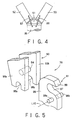
- Fig. 5 is a fragmentary perspective view of the hinge mechanism 76 and Fig. 6 is a sectional view of the hinge mechanism 76 and members associated with the hinge mechanism 76.
- the other hinge mechanisms 70, 71 and 75 are similar in construction as the hinge mechanism 76.
- the hinge mechanism 76 has a movable joint member 90 attached to the first side wall segment 53, and a fixed joint member 91 attached to the first support structure 51.
- the movable joint member 90 has a pair plates 93a and 93b disposed in parallel to and spaced each other, and a retaining pin 94 extended between the pair of plates 93a and 93b.
- the plates 93a and 93b of the movable joint member 90 are provided in their base end portions on the fairing-base side with slots 95a and 95b extending away from the retaining pin 94 and opening in the base ends, respectively.
- the fixed joint member 91 has a plate 98 and a pair of hinge pins 96a and 96b attached to the opposite side surfaces of the plate 98 coaxially with each other.
- the fixed joint member 91 is provided with an open slot 97 for receiving the retaining pin 94 of the movable joint member 90, formed in its forward portion on the fairing-forward side so as to extend inwardly from its outer side along an arc of a circle having its center on the common axis L10 of the hinge pins 96a and 96b.
- the plate 98 of the fixed joint member 91 is disposed between the plates 93a and 93b of the movable joint member 90 with the hinge pins 96a and 96b fitted in the slots 95a and 95b of the movable joint member 90, respectively.
- the movable joint member 90 is only able to turn relative to the fixed joint member 91 about the common axis L10 of the hinge pins 96a and 96b.
- the movable joint member 90 is able to move away from the fixed joint member 91.
- the movable joint member 90 is able to turn relative to the fixed joint member 91 about the common axis L10 of the hinge pins 96a and 96b and is restrained from moving away from the fixed joint member 91 when the retaining pin 94 is at a position between the bottom of the slot 97 as shown in (1) of Fig. 7 and the open end of the slot 97 as shown in (2) of Fig. 7.
- the movable joint member 90 and the fixed joint member 91 are kept connected so that the movable joint member 90 is able to turn about the common axis L10 of the hinge pins 96a and 96b relative to the fixed joint member 91 when at least a portion of the retaining pin 94 is in a range between the bottom of the slot 97 and a plane 160 (Fig. 6) including the free end 99a of a hook portion 99 defining forward boundary of the slot 97 on the fairing-forward side and the common axis L10 of the hinge pins 96a and 96b.
- the hinge pins 96a and 96b are able to move out of the slots 95a and 95b, so that the movable joint member 90 is able to separate from the fixed joint member 91.
- the opening mechanisms 87 and 88 capable of serving also as holding mechanisms stop the opening motions of the first side wall segments 52 and 53 before the hinge mechanisms 75 and 76 are turned to positions corresponding to that shown in (3) of Fig. 7 and hold the first side wall segments 52 and 53 at the predetermined angle (angular position).
- the movable joint member 90 and the fixed joint member 91 of each of the hinge mechanisms 75 and 76 are kept connected.
- the fastening mechanism 153 shown in Fig. 1 has bolts 101 and nuts 102 for fastening together the first support structure 51 and the first side wall segment 53, and expandable shielded mild detonating cords (abbreviated to "ESMDCs") 103.
- ESMDCs expandable shielded mild detonating cords
- the first support structure 51 and the first side wall segment 53 have opposite walls 105 and 106, respectively.
- the bolts 101 are passed through holes formed in the opposite walls 105 and 106 at substantially equal angular intervals from the side of the first side wall segment 53, and the nuts 102 are screwed on the bolts 101 from the side of the first support structure 51.
- T-shaped holding members 108 are put on the bolts 101, respectively, on the side of the first side wall segment 53.
- the ESMDC 103 is formed in a shape like a cord by sealing an explosive in a metal-coated tube.
- the ESMDCs 103 are extended in the entire region between the first support structure 51 and the first side wall segment 53, i.e., along the entire circular base end of the first side wall segment 53.
- the bolts 101 are arranged on the base end of the first side wall segment 53 at angular intervals, the ESMDCs 103 are held between the holding members 108 put on the bolts 101 and the wall 105, the nuts 102 are screwed on the bolts 101 to fasten together the first support structure 51 and the first side wall segment 53 with the ESMDCs 103 compressed between the holding members 108 and the wall 105, respectively.
- the two ESMDCs are extended on the opposite sides of each of the bolts 101, respectively.
- the ESMDCs 103 are connected individually to detonating devices. Each of the bolts 101 is broken at a neck formed therein by detonating the ESMDC 103. Consequently, the first side wall segment 53 is unfastened from the first support structure 51. Even if one of the two ESMDCs 103 cannot be detonated due to the malfunction of the associated detonating device, the bolts 101 can be broken by detonating the other ESMDC 103 because the two ESMDCs 103 are detonated individually by the two detonating devices. Therefore, the first side wall segment 53 can be unfastened from the first support structure 51 with reliability.
- the other fastening mechanisms 72 to 74 and 150 to 152 are the same in function, construction and effect as the fastening mechanism 153.
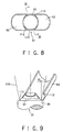
- Fig. 8 is a top plan view of a portion of the fairing 30 shown in Fig. 4, and Fig. 9 is a sectional view taken on line IX-IX in Fig. 8.
- Figs. 8 and 9 indicated at 110 is an imaginary circle representing the boundary of the base end of the first storage space 36 on the fairing-base side, at ⁇ 1 is the inclination of the first side wall segment 53 to the longitudinal axis of the fairing 30 and at 115 is an imaginary frustum representing the boundary of a region in which the first satellite 32 is able to move without colliding against the first side wall segments 52 and 53.
- the surface of the frustum including the line 115 expands toward the forward end of the fairing 30.
- An angular position at which the first side wall segment 52 be held is determined similarly.
- Fig. 10 shows a fairing 30A in a first modification of the fairing 30 shown in Fig. 1 in a front elevation.
- the fairing 30 shown in Fig. 1 employs the opening mechanisms 87 and 88 comprising springs for turning the first side wall segments 52 and 53.
- the fairing 30A employs an opening mechanism 89 comprising a compression coil spring and connected to first side wall segments 52 and 53 instead of the opening mechanisms 87 and 88.
- the opening mechanism 89 is capable of turning the first side wall segments 52 and 53 in opening directions and of holding the first side wall segments 52 and 53 at a predetermined angular position.
- the fairing 30A employing the opening mechanism 89 is the same in effect as the fairing 30.
- Fig. 11 shows a fairing 30B in a second modification of the fairing 30 shown in Fig. 1 in a schematic front elevation and Fig. 12 shows the fairing 30B in an exploded front elevation.
- a middle dividing structure 54 is divided into two parts 170 and 171 each having a shape formed by dividing a frustum along a plane including its longitudinal axis, and the parts 170 and 171 are formed integrally with the first side wall segments 52 and 53 to form two covering shells 52B and 53B, respectively.
- the middle dividing structure 54 and the first side wall segments 52 and 53 are separated from each other to open the first storage space 36.
- the middle dividing structure 54 and the first side wall segments 52 and 53 are divided into the covering shells 52B and 53B.
- the fairing 30B reduces the number of components and the number of individual components scattered in space, and prevents the increase of space contaminants thrown into and drifting in space.
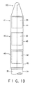
- Fig. 13 shows a fairing 30C in a third modification of the fairing 30 shown in Fig. 1 in a front elevation.
- the fairing 30C has a plurality of first structures 40 successively arranged along the longitudinal axis of the fairing 30B and connected together, and a second structure 41 connected to the first structure 40 on the fairing-forward side.
- the second structure 41 is opened and a third satellite 33 is released into space, and then the plurality of first structures 40 are opened sequentially from the first structure 40 nearest to the forward end of the fairing 30C toward the first structure 40 nearest to the base end of the fairing 30C to release first satellites 32 contained therein sequentially into space.
- the side walls 43 of the first structures 40 other than the side wall 43 of the first structure 40 nearest to the base end of the fairing 40C are thrown into space after opening the first structures 40.
- the side wall 43 of the first structure 40 nearest to the base end of the fairing 30C may be thrown into space or may be kept connected to the forward section 35 of the body 31 after opening the same first structure 40.
- the present invention is not limited in its practical application to the embodiment and the modifications of the same specifically described herein and changes in shape and the like are possible therein.
- the middle dividing structure 54 may be formed integrally with one of the first side wall segments 52 and 53 without dividing the same into two parts.
- the payloads need not be limited to satellites but may be space probes, space crafts and the like.
- the first side wall segments 52 and 53 forming the first side wall 43 surrounding the first satellite 32 disposed on the fairing-base side may be disconnected from the body 31 and thrown into space when releasing the first satellite 32 into space.
- the first side wall segments 52 and 53 of the first side wall 43 surrounding the first satellite 32 are disconnected from the body 31 after the second satellite 33 has been released into space, and then the first satellite 32 is moved to the higher orbit.
- the first side wall 43 is thrown into space before moving the first satellite 32 to its orbit, the first side wall 43 need not be carried to the orbit of the first satellite 32 and hence power can be saved. Therefore, the first satellite 32 can be launched onto a higher orbit by using the same power.
- the first side wall 43 and the second side wall 44 can be divided into more than two pieces, respectively, along several planes including the longitudinal axis of the fairing.
- the first side wall surrounding the first payload is opened along a plane or planes including the longitudinal axis of the fairing into the plurality of first side wall segments, and the plurality of first side wall segments can be turned away from the first payload to secure a wide space around a path along which the first satellite is released. Therefore, a large available storage region can be secured in the first storage space surrounded by the first side wall, and allowable dimensions of the first payload can be increased.
Landscapes
- Engineering & Computer Science (AREA)
- Remote Sensing (AREA)
- Aviation & Aerospace Engineering (AREA)
- Physics & Mathematics (AREA)
- Acoustics & Sound (AREA)
- Aiming, Guidance, Guns With A Light Source, Armor, Camouflage, And Targets (AREA)
- Details Of Aerials (AREA)
- Earth Drilling (AREA)
- Laminated Bodies (AREA)
Claims (15)
- Raketenverkleidung (30), die an einem vorderen Abschnitt (35) eines in einer Rakete enthaltenen Raketenkörpers (31) angebracht ist, wobei die Raketenverkleidung aufweist:eine erste Struktur (40) zur Aufnahme einer ersten Nutzlast (32), die an der Verkleidungsbasisseite angeordnet ist; wobei die erste Struktur eine erste Seitenwand (43) aufweist, die einen ersten Aufnahmeraum (36) zum Aufnehmen der ersten Nutzlast definiert, und eine erste Tragstruktur (51) im ersten Aufnahmeraum angeordnet ist, um die erste Nutzlast an ihrem Basisteil zu tragen; wobei die erste Seitenwand (43) eine Mehrzahl von ersten Seitenwandsegmenten (52, 53) aufweist, die entlang einer eine Längsachse der Verkleidung (30) enthaltenden Ebene aneinander stoßen und die befähigt sind, voneinander entlang dieser Ebene getrennt zu werden und von der ersten Nutzlast weggedreht zu werden, wenn die erste Nutzlast vom ersten Aufnahmeraum freigeben wird; undeine zweite Struktur (41) zur Aufnahme einer an einer Verkleidungsvorderseite angeordneten zweiten Nutzlast (33), die mit einem vorderen Ende der ersten Struktur (40) an der Verkleidungsvorderseite verbunden ist und einen vorderen Abschnitt der Verkleidung bildet, wobei die Raketenverkleidung weiter eine zweite Tragstruktur (42) aufweist, die ausgebildet ist, um die zweite Nutzlast (33) zu tragen, wobei die zweite Tragstruktur eine Mehrzahl von zweiten Tragsegmenten (44) aufweist, die jeweils integral mit den ersten Seitenwandsegmenten ausgebildet sind, dadurch gekennzeichnet, dass die zweiten Tragsegmente gemeinsam mit den ersten Seitenwandsegmenten geöffnet werden, wenn die erste Seitenwand geöffnet wird.
- Raketenverkleidung nach Anspruch 1, bei der ein Basisende eines jeden der ersten Seitenwandsegmente (52, 53) mit dem vorderen Abschnitt des Raketenkörpers durch einen Scharniermechanismus (75, 76) schwenkbar verbunden ist, welcher erste und zweite Verbindungselemente (90, 91) aufweist, die befähigt sind, sich voneinander zu trennen, wenn das erste Seitenwandsegment (52, 53) um einen Winkel gedreht wird, der größer ist als ein vorbestimmter Winkel.
- Raketenverkleidung nach Anspruch 2, bei der das erste Verbindungselement (90) des Scharniermechanismus ein bewegliches Verbindungselement (90) ist, das am Basisende des ersten Seitenwandsegmentes (52, 53) befestigt ist und mit einem Rückhaltestift (94) versehen ist, und das zweite Verbindungselement (91) ein feststehendes Verbindungselement (91) ist, das am Raketenkörper befestigt ist und mit einem Scharnierstift (96a, 96b) versehen ist, das bewegliche Verbindungselement (90) mit einem Schlitz zur Aufnahme des Gelenkstiftes des feststehenden Verbindungselementes versehen ist, wobei der Schlitz (95a, 95b) in einem Basisende des beweglichen Verbindungselementes ausgebildet ist, so dass er sich zur Verkleidungsvorderseite hin erstreckt, und
das feststehende Verbindungselement (91) mit einem Schlitz (97) zur Aufnahme des Rückhaltestiftes des beweglichen Verbindungselementes versehen ist, wobei der Schlitz in einem vorderen Teilstück des feststehenden Verbindungselementes ausgebildet ist, so dass er sich von einer Außenseite des feststehenden Verbindungselementes nach innen erstreckt. - Raketenverkleidung nach einem der Ansprüche 1 bis 3, bei der eine Mehrzahl von den ersten Strukturen Ende an Ende verbunden sind und die zweite Struktur mit der ersten Struktur ganz nahe bei einem vorderen Ende der Verkleidung verbunden ist.
- Raketenverkleidung nach Anspruch 2 oder 3, die weiter eine Halteeinrichtung aufweist, die einen Öffnungswinkel der ersten Seitenwandsegmente bei einem Winkel hält, der kleiner ist als der vorbestimmte Winkel, damit die ersten Seitenwandsegmente auf dem vorderen Abschnitt des Raketenkörpers verbleiben, nachdem die erste Seitenwand geöffnet ist.
- Raketenverkleidung nach einem der Ansprüche 1 bis 5, die weiter eine Öffnungseinrichtung aufweist, welche Kräfte auf die ersten Seitenwandsegmente aufbringt, um diese von der ersten Nutzlast wegzubewegen, wenn die erste Seitenwand geöffnet wird.
- Raketenverkleidungsöffnungsverfahren zum Öffnen einer Raketenverkleidung (30), die an einem vorderen Abschnitt (35) eines in einer Rakete enthaltenen Raketenkörpers (31) angebracht ist, aufweisend: eine erste Struktur (40) zur Aufnahme einer ersten Nutzlast (32), die auf der Verkleidungsbasisseite angeordnet ist, wobei die erste Struktur eine erste Seitenwand (43) beinhaltet, welche einen ersten Aufnahmeraum zum Aufnehmen der ersten Nutzlast definiert, wobei die erste Seitenwand (43) eine Mehrzahl von ersten Seitenwandsegmenten (52, 53) aufweist, die entlang einer eine Längsachse der Verkleidung (30) enthaltenden Ebene aneinander stoßen und die befähigt sind, voneinander entlang dieser Ebene getrennt zu werden, und eine erste Tragstruktur (51) im ersten Aufnahmeraum angeordnet ist, um die erste Nutzlast an ihrem Basisteil zu tragen; und eine zweite Struktur (41) zur Aufnahme einer auf einer Verkleidungsvorderseite angeordneten zweiten Nutzlast, die mit einem vorderen Ende der ersten Struktur an der Verkleidungsvorderseite verbunden ist und einen vorderen Abschnitt der Verkleidung bildet, wobei die zweite Struktur eine zweite Seitenwand aufweist, welche einen zweiten Aufnahmeraum zum Aufnehmen der zweiten Nutzlast definiert, wobei die zweite Seitenwand eine Mehrzahl von zweiten Seitenwandsegmenten (55, 56) aufweist, die entlang einer eine Längsachse der Verkleidung (30) enthaltenden Ebene aneinander stoßen und die befähigt sind, voneinander entlang dieser Ebene getrennt zu werden und von der zweiten Nutzlast weggedreht zu werden; wobei das Verfahren folgende Schritte beinhaltet:Öffnen der zweiten Seitenwand der den zweiten Aufnahmeraum definierenden zweiten Struktur, indem die zweite Seitenwand entlang dieser Ebene in die zweiten Seitenwandsegmente (55, 56) geteilt wird und die zweiten Seitenwandsegmente von der zweiten Nutzlast wegbewegt werden, bevor die zweite Nutzlast von der zweiten Tragstruktur getrennt wird und die zweite Nutzlast freigegeben wird; undÖffnen der ersten Seitenwand der den ersten Aufnahmeraum definierenden ersten Struktur, indem die erste Seitenwand entlang dieser Ebene in die ersten Seitenwandsegmente (52, 53) geteilt wird und die ersten Seitenwandsegmente und die zweite Tragstruktur von der ersten Nutzlast wegbewegt werden, bevor die erste Nutzlast von der ersten Tragstruktur getrennt wird und die erste Nutzlast freigegeben wird;wobei die zweite Tragstruktur eine Mehrzahl von zweiten Tragsegmenten aufweist, die jeweils integral mit den ersten Seitenwandsegmenten ausgebildet sind, dadurch gekennzeichnet, dass die zweiten Tragsegmente gemeinsam mit den ersten Seitenwandsegmenten geöffnet werden, wenn die erste Seitenwand geöffnet wird.
- Raketenverkleidungsöffnungsverfahren nach Anspruch 7, bei dem die ersten Seitenwandsegmente von dem vorderen Abschnitt des Raketenkörpers der Rakete getrennt werden, wenn die erste Seitenwand geöffnet wird.
- Raketenverkleidungsöffnungsverfahren nach Anspruch 8, bei dem ein Basisende eines jeden der ersten Seitenwandsegmente mit dem vorderen Abschnitt des Raketenkörpers durch einen Scharniermechanismus schwenkbar verbunden ist, welcher erste und zweite Verbindungselemente aufweist, die befähigt sind, sich voneinander zu trennen, wenn das erste Seitenwandsegment um einen Winkel geschwenkt wird, der einen vorbestimmten Winkel übersteigt.
- Raketenverkleidungsöffnungsverfahren nach Anspruch 9, bei dem das erste Verbindungselement des Scharniermechanismus ein bewegliches Verbindungselement ist, das am Basisende des ersten Seitenwandsegmentes befestigt ist und mit einem Rückhaltestift versehen ist, und das zweite Verbindungselement ein feststehendes Verbindungselement ist, das am Raketenkörper der Rakete befestigt ist und mit einem Scharnierstift versehen ist,
das bewegliche Verbindungselement mit einem Schlitz zur Aufnahme des Gelenkstiftes des feststehenden Verbindungselementes versehen ist, wobei der Schlitz in einem Basisende des beweglichen Verbindungselementes ausgebildet ist, so dass er sich zur Verkleidungsvorderseite hin erstreckt,
das feststehende Verbindungselement mit einem Schlitz zur Aufnahme des Rückhaltestiftes des beweglichen Verbindungselementes versehen ist, wobei der Schlitz in einem vorderen Teilstück des feststehenden Verbindungselementes ausgebildet ist, so dass er sich von einer Außenseite des feststehenden Verbindungselementes nach innen erstreckt,
sich das bewegliche Scharnierelement gemeinsam mit dem ersten Seitenwandsegment auf dem Scharnierstift des feststehenden Verbindungselementes dreht, sich der Rückhaltestift des beweglichen Verbindungselementes aus dem Schlitz des feststehenden Verbindungselementes heraus bewegt und sich das bewegliche Verbindungselement von dem Schwenkstift des feststehenden Verbindungselementes trennt, wenn das erste Seitenwandsegment um einen Winkel geschwenkt wird, der größer ist als der vorbestimmte Winkel, und sich jedes der ersten Seitenwandsegmente von dem vorderen Abschnitt des Raketenkörpers der Rakete trennt. - Raketenverkleidungsöffnungsverfahren nach einem der Ansprüche 7 bis 10, bei dem eine Mehrzahl von den ersten Strukturen Ende an Ende verbunden sind, und die zweite Struktur mit der ersten Struktur ganz nahe bei einem vorderen Ende der Verkleidung verbunden ist, und
die Strukturen sukzessive geöffnet werden, und zwar beginnend von der ersten Struktur ganz nah am vorderen Ende der Verkleidung hin zur ersten Struktur ganz nahe am Basisende der Verkleidung, um eine Mehrzahl von ersten Nutzlasten sukzessive freizugeben, und zwar nach Öffnen der zweiten Struktur und Freigeben der zweiten Nutzlast. - Raketenverkleidungsöffnungsverfahren nach Anspruch 7, bei dem die ersten Seitenwandsegmente der ersten Seitenwand nach dem Öffnen der ersten Seitenwand auf dem vorderen Abschnitt des Raketenkörpers der Rakete verbleiben.
- Raketenverkleidungsöffnungsverfahren nach Anspruch 12, bei dem ein Basisende eines jeden der ersten Seitenwandsegmente mit dem vorderen Abschnitt der Rakete durch einen Scharniermechanismus schwenkbar verbunden ist, welcher erste und zweite Verbindungselemente aufweist, die befähigt sind, sich voneinander zu trennen, wenn das erste Seitenwandsegment um einen Winkel gedreht wird, der größer ist als ein vorbestimmter Winkel,
die ersten Seitenwandsegmente durch eine Halteeinrichtung bei einem Winkel gehalten werden, der kleiner ist als der vorbestimmte Winkel, um die ersten Seitenwandsegmente am vorderen Abschnitt des Raketenkörpers der Rakete zu halten, wenn die erste Seitenwand geöffnet ist. - Raketenverkleidungsöffnungsverfahren nach Anspruch 13, bei dem das erste Verbindungselement des Scharniermechanismus ein bewegliches Verbindungselement ist, das am Basisende des ersten Seitenwandsegmentes befestigt ist und mit einem Rückhaltestift versehen ist, und das zweite Verbindungselement ein feststehendes Verbindungselement ist, das am Raketenkörper der Rakete befestigt ist und mit einem Scharnierstift versehen ist,
das bewegliche Verbindungselement mit einem Schlitz zur Aufnahme des Gelenkstiftes des feststehenden Verbindungselementes versehen ist, wobei der Schlitz in einem Basisende des beweglichen Verbindungselementes ausgebildet ist, so dass er sich zur Verkleidungsvorderseite hin erstreckt,
das feststehende Verbindungselement mit einem Schlitz zur Aufnahme des Rückhaltestiftes des beweglichen Verbindungselementes versehen ist, wobei der Schlitz in einem vorderen Teilstück des feststehenden Verbindungselementes ausgebildet ist, so dass er sich von einer Außenseite des feststehenden Verbindungselementes nach innen erstreckt,
sich das bewegliche Verbindungselement auf dem Schwenkstift des feststehenden Verbindungselementes gemeinsam mit dem ersten Seitenwandsegment dreht, wenn die erste Seitenwand geöffnet wird, das erste Seitenwandsegment durch die Halteeinrichtung daran gehindert wird, sich zu drehen, bevor sich das erste Seitenwandsegment um einen Winkel gedreht ist, der größer ist als der vorbestimmte Winkel, und die ersten Seitenwandsegmente in einer geöffneten Position bei einem Winkel gehalten werden, der kleiner ist als der vorbestimmte Winkel. - Raketenverkleidungsöffnungsverfahren nach einem der Ansprüche 7 bis 14, bei dem eine Kraft, welche die ersten Seitenwandsegmente von der ersten Nutzlast weg bewegt, an die ersten Seitenwandsegmente durch eine Öffnungseinrichtung zum Öffnen der ersten Seitenwand aufgebracht wird.
Applications Claiming Priority (2)
| Application Number | Priority Date | Filing Date | Title |
|---|---|---|---|
| JP36785898 | 1998-12-24 | ||
| JP36785898A JP3223171B2 (ja) | 1998-12-24 | 1998-12-24 | ロケットフェアリングの分割構造および分割方法 |
Publications (3)
| Publication Number | Publication Date |
|---|---|
| EP1013546A2 EP1013546A2 (de) | 2000-06-28 |
| EP1013546A3 EP1013546A3 (de) | 2000-12-20 |
| EP1013546B1 true EP1013546B1 (de) | 2006-03-08 |
Family
ID=18490381
Family Applications (1)
| Application Number | Title | Priority Date | Filing Date |
|---|---|---|---|
| EP99125840A Expired - Lifetime EP1013546B1 (de) | 1998-12-24 | 1999-12-23 | Raketennutzlastverkleidung und ihr Öffnungsverfahren |
Country Status (3)
| Country | Link |
|---|---|
| US (1) | US6494406B1 (de) |
| EP (1) | EP1013546B1 (de) |
| JP (1) | JP3223171B2 (de) |
Cited By (2)
| Publication number | Priority date | Publication date | Assignee | Title |
|---|---|---|---|---|
| RU2558957C1 (ru) * | 2014-06-18 | 2015-08-10 | Федеральное государственное бюджетное учреждение науки Институт космических исследований Российской академии наук | Транспортно-пусковой контейнер |
| RU2602873C2 (ru) * | 2011-03-09 | 2016-11-20 | Астриум Сас | Способ и устройство для последовательного запуска двух спутников |
Families Citing this family (46)
| Publication number | Priority date | Publication date | Assignee | Title |
|---|---|---|---|---|
| SE515850C2 (sv) * | 2000-09-18 | 2001-10-15 | Saab Ericsson Space Ab | Anordning och metod vid en rymdfarkost |
| US7036773B2 (en) * | 2003-08-28 | 2006-05-02 | Ecliptic Enterprises Corporation | Compact external launcher for small space payloads |
| DE102006043660B4 (de) * | 2006-09-18 | 2008-07-10 | Astro- Und Feinwerktechnik Adlershof Gmbh | Transport- und Auswurfeinheit für Picosatelliten |
| US7905453B2 (en) * | 2006-12-21 | 2011-03-15 | Intelsat | Piggyback equipment panel payload arrangement, a device for and method of attaching a hosted secondary piggyback payload and adapter to be used for a piggyback secondary payload arrangement for launching the piggyback equipment panel secondary |
| US7866607B2 (en) * | 2006-12-21 | 2011-01-11 | Intelsat | Piggyback satellite payload arrangement, a device for and method of attaching a piggyback satellite payload and adapter to be used for a piggyback satellite payload arrangement for launching the piggyback satellite |
| JP5213031B2 (ja) * | 2008-06-04 | 2013-06-19 | 株式会社Ihiエアロスペース | 結合分離装置 |
| US8727654B2 (en) | 2008-07-22 | 2014-05-20 | Ensign-Bickford Aerospace & Defense Company | Separation system with shock attenuation |
| FR2945515B1 (fr) * | 2009-05-12 | 2012-06-01 | Astrium Sas | Systeme comportant une sonde spatiale mere formant vehicule spatial porteur et une pluralite de sondes spatiales filles |
| JP5417040B2 (ja) * | 2009-05-25 | 2014-02-12 | 株式会社Ihiエアロスペース | スライド式フェアリング脱頭装置及びスライド式フェアリング脱頭方法 |
| JP5554030B2 (ja) * | 2009-07-31 | 2014-07-23 | 三菱重工業株式会社 | カバー、移動体及びカバー分離方法 |
| US9567107B2 (en) | 2009-09-25 | 2017-02-14 | Quicklaunch, Inc. | Gas gun launcher |
| WO2011038369A1 (en) | 2009-09-25 | 2011-03-31 | John William Hunter | Vehicle for launching from a gas gun |
| US8485475B2 (en) * | 2009-12-16 | 2013-07-16 | Daniel W. Allen | Debris removal management system and method of operation thereof |
| DE102010007064B4 (de) * | 2010-02-06 | 2012-03-29 | Diehl Bgt Defence Gmbh & Co. Kg | Flugkörperkopf und Verfahren zum Trennen einer Haube von einem Rumpf eines Flugkörpers |
| JP5569136B2 (ja) * | 2010-05-12 | 2014-08-13 | 株式会社Ihi | ペイロード保護装置 |
| JP2013226886A (ja) * | 2012-04-25 | 2013-11-07 | Seccia Techno:Kk | 物品の保持分離装置 |
| US8939409B2 (en) | 2012-05-07 | 2015-01-27 | The Johns Hopkins University | Adaptor system for deploying small satellites |
| US9180984B2 (en) | 2012-05-11 | 2015-11-10 | The Boeing Company | Methods and apparatus for performing propulsion operations using electric propulsion systems |
| US8915472B2 (en) * | 2012-05-11 | 2014-12-23 | The Boeing Company | Multiple space vehicle launch system |
| US9027889B2 (en) * | 2013-02-28 | 2015-05-12 | The Boeing Comapny | Modular core structure for dual-manifest spacecraft launch |
| FR3004166B1 (fr) * | 2013-04-09 | 2015-04-17 | Astrium Sas | Systeme de satellites comportant deux satellites fixes l'un a l'autre et procede pour leur mise en orbite |
| FR3008070B1 (fr) * | 2013-07-08 | 2020-11-06 | Astrium Sas | Bloc propulseur pour vehicule de lancement reutilisable |
| CN104699877B (zh) * | 2013-12-10 | 2017-11-17 | 上海宇航系统工程研究所 | 一种新的卫星整流罩虚拟分离方法 |
| FR3022995B1 (fr) * | 2014-06-25 | 2017-06-09 | Mbda France | Missile pourvu d'une coiffe de protection separable |
| US9718566B2 (en) * | 2015-04-30 | 2017-08-01 | Worldvu Satellites Limited | Stackable satellites and method of stacking same |
| US10254094B1 (en) * | 2015-11-16 | 2019-04-09 | Northrop Grumman Systems Corporation | Aircraft shroud system |
| JP6564319B2 (ja) * | 2015-12-15 | 2019-08-21 | 川崎重工業株式会社 | フェアリング |
| JP6502842B2 (ja) * | 2015-12-15 | 2019-04-17 | 川崎重工業株式会社 | フェアリングの組立方法 |
| US11267588B2 (en) | 2016-04-29 | 2022-03-08 | Quicklaunch, Inc. | Orbital mechanics of impulsive launch |
| US10427804B1 (en) | 2016-04-29 | 2019-10-01 | Quicklaunch, Inc. | Orbital mechanics of impulsive launch |
| FR3065521B1 (fr) * | 2017-04-21 | 2019-06-28 | Mbda France | Missile pourvu d'une coiffe separable comprenant au moins une coque ejectable cooperant avec un element de support |
| US10669048B1 (en) * | 2017-06-15 | 2020-06-02 | United Launch Alliance, L.L.C. | Mechanism for increasing jettison clearance |
| JP6900294B2 (ja) * | 2017-10-23 | 2021-07-07 | 株式会社Ihiエアロスペース | ノーズフェアリングの開頭機構 |
| IL258729B (en) * | 2018-04-16 | 2021-12-01 | Israel Aerospace Ind Ltd | Nano-satellite |
| US10377510B1 (en) * | 2018-11-14 | 2019-08-13 | Vector Launch Inc. | Enhanced fairing mechanisms for launch systems |
| CN113654416A (zh) * | 2019-02-13 | 2021-11-16 | 蓝箭航天空间科技股份有限公司 | 用于运载火箭中整流罩的气动分离系统 |
| WO2020218569A1 (ja) * | 2019-04-26 | 2020-10-29 | 川崎重工業株式会社 | ノーズフェアリング |
| CN112625391B (zh) * | 2019-10-08 | 2023-03-31 | 中国人民解放军69007部队 | 夜光标识剂、制备方法及其应用的标识弹头 |
| CN111542198B (zh) * | 2020-04-28 | 2021-08-03 | 中国科学院空间应用工程与技术中心 | 一种具有导热结构的载荷适配器 |
| CN112815789B (zh) * | 2021-01-21 | 2023-05-16 | 东方空间技术(山东)有限公司 | 一种弹簧推冲作用的整流罩平抛分离装置 |
| CN113173270B (zh) * | 2021-04-13 | 2023-04-07 | 西安航天动力技术研究所 | 一种分段式活塞分离机构 |
| CN113203326A (zh) * | 2021-04-28 | 2021-08-03 | 北京星途探索科技有限公司 | 一种整流罩旋抛铰链结构 |
| CN115158709B (zh) * | 2022-06-07 | 2022-12-27 | 精易兴航(北京)科技创新有限公司 | 一种具有气动分离和回收动力系统的运载火箭 |
| FR3138123A1 (fr) * | 2022-07-25 | 2024-01-26 | Arianegroup Sas | Enceinte annulaire d’étage intermédiaire d’un lanceur aérospatial avec ralentisseur de chute |
| CN115127407A (zh) * | 2022-08-10 | 2022-09-30 | 北京凌空天行科技有限责任公司 | 一种基于弹簧的火箭头罩分离装置 |
| CN117760272A (zh) * | 2024-02-22 | 2024-03-26 | 江苏深蓝航天有限公司 | 一种整流罩、航天火箭 |
Family Cites Families (5)
| Publication number | Priority date | Publication date | Assignee | Title |
|---|---|---|---|---|
| FR2649667B1 (fr) * | 1989-07-17 | 1991-09-20 | Centre Nat Etd Spatiales | Procede de lancement dans l'espace d'une capsule et moyen de lancement correspondant |
| JPH06308745A (ja) | 1993-04-22 | 1994-11-04 | F I T:Kk | 電子写真感光体 |
| US5529264A (en) * | 1994-02-18 | 1996-06-25 | Lockheed Missiles & Space Company, Inc. | Launch vehicle system |
| FR2717770B1 (fr) * | 1994-03-22 | 1996-06-14 | Aerospatiale | Distributeur multisatellite pour lanceur. |
| JPH08164899A (ja) * | 1994-12-13 | 1996-06-25 | Mitsubishi Heavy Ind Ltd | 複数人工衛星搭載機構 |
-
1998
- 1998-12-24 JP JP36785898A patent/JP3223171B2/ja not_active Expired - Lifetime
-
1999
- 1999-12-20 US US09/466,868 patent/US6494406B1/en not_active Expired - Fee Related
- 1999-12-23 EP EP99125840A patent/EP1013546B1/de not_active Expired - Lifetime
Cited By (2)
| Publication number | Priority date | Publication date | Assignee | Title |
|---|---|---|---|---|
| RU2602873C2 (ru) * | 2011-03-09 | 2016-11-20 | Астриум Сас | Способ и устройство для последовательного запуска двух спутников |
| RU2558957C1 (ru) * | 2014-06-18 | 2015-08-10 | Федеральное государственное бюджетное учреждение науки Институт космических исследований Российской академии наук | Транспортно-пусковой контейнер |
Also Published As
| Publication number | Publication date |
|---|---|
| JP3223171B2 (ja) | 2001-10-29 |
| EP1013546A3 (de) | 2000-12-20 |
| EP1013546A2 (de) | 2000-06-28 |
| US6494406B1 (en) | 2002-12-17 |
| JP2000185699A (ja) | 2000-07-04 |
Similar Documents
| Publication | Publication Date | Title |
|---|---|---|
| EP1013546B1 (de) | Raketennutzlastverkleidung und ihr Öffnungsverfahren | |
| JP7110469B2 (ja) | 可変なスラスター制御を用いた軌道上サービスを提供するためのサービス衛星 | |
| EP3699097B1 (de) | Systeme und verfahren zum abschuss einer vielzahl von raumfahrzeugen | |
| US5743492A (en) | Payload housing and assembly joint for a launch vehicle | |
| US5529264A (en) | Launch vehicle system | |
| JP6019044B2 (ja) | 宇宙空間を自由に飛行している物体の回収・制動装置 | |
| US4943014A (en) | Soft ride method for changing the altitude or position of a spacecraft in orbit | |
| US5318255A (en) | Stage separation mechanism for space vehicles | |
| US4506852A (en) | Payload deployment from launch vehicle using canted springs for imparting angular and linear velocities | |
| EP0194287A1 (de) | Satellitentransportanlage. | |
| RU2237601C2 (ru) | Система для изменения жесткости/демпфирующих свойств силовых соединений | |
| EP1675770B1 (de) | Stossarme trennfuge und betriebsverfahren | |
| US6547476B2 (en) | Universal spacecraft separation node | |
| US4324374A (en) | Integrated spacecraft and cradle structure | |
| US4300737A (en) | Satellite deployment system with remotely controlled relocking capability | |
| US6568330B1 (en) | Modular missile and method of assembly | |
| US4646994A (en) | Spacecraft support and separation system | |
| US4860974A (en) | Payload deployment method and system | |
| JP5417040B2 (ja) | スライド式フェアリング脱頭装置及びスライド式フェアリング脱頭方法 | |
| US4326684A (en) | Spacecraft with internal propulsion stages | |
| US5983802A (en) | Separation system | |
| US4290570A (en) | Three point attachment for an ejectable spacecraft | |
| US4213586A (en) | Spin activated safety circuit for spacecraft | |
| JPH08164899A (ja) | 複数人工衛星搭載機構 | |
| KR102664654B1 (ko) | 우주발사체용 위성 다중탑재 시스템 |
Legal Events
| Date | Code | Title | Description |
|---|---|---|---|
| PUAI | Public reference made under article 153(3) epc to a published international application that has entered the european phase |
Free format text: ORIGINAL CODE: 0009012 |
|
| 17P | Request for examination filed |
Effective date: 19991223 |
|
| AK | Designated contracting states |
Kind code of ref document: A2 Designated state(s): CH FR GB LI |
|
| AX | Request for extension of the european patent |
Free format text: AL;LT;LV;MK;RO;SI |
|
| PUAL | Search report despatched |
Free format text: ORIGINAL CODE: 0009013 |
|
| RIC1 | Information provided on ipc code assigned before grant |
Free format text: 7B 64G 1/00 A, 7F 42B 12/58 B, 7B 64G 1/64 B |
|
| AK | Designated contracting states |
Kind code of ref document: A3 Designated state(s): AT BE CH CY DE DK ES FI FR GB GR IE IT LI LU MC NL PT SE |
|
| AX | Request for extension of the european patent |
Free format text: AL;LT;LV;MK;RO;SI |
|
| AKX | Designation fees paid |
Free format text: CH FR GB LI |
|
| REG | Reference to a national code |
Ref country code: DE Ref legal event code: 8566 |
|
| RAP1 | Party data changed (applicant data changed or rights of an application transferred) |
Owner name: KAWASAKI JUKOGYO KABUSHIKI KAISHA Owner name: NATIONAL SPACE DEVELOPMENT AGENCY OF JAPAN |
|
| 17Q | First examination report despatched |
Effective date: 20041229 |
|
| GRAP | Despatch of communication of intention to grant a patent |
Free format text: ORIGINAL CODE: EPIDOSNIGR1 |
|
| GRAS | Grant fee paid |
Free format text: ORIGINAL CODE: EPIDOSNIGR3 |
|
| RAP1 | Party data changed (applicant data changed or rights of an application transferred) |
Owner name: KAWASAKI JUKOGYO KABUSHIKI KAISHA Owner name: INDEPENDENT ADMINISTRATIVE INSTITUTION, THE JAPANA |
|
| GRAA | (expected) grant |
Free format text: ORIGINAL CODE: 0009210 |
|
| AK | Designated contracting states |
Kind code of ref document: B1 Designated state(s): CH FR GB LI |
|
| REG | Reference to a national code |
Ref country code: GB Ref legal event code: FG4D |
|
| REG | Reference to a national code |
Ref country code: CH Ref legal event code: EP |
|
| REG | Reference to a national code |
Ref country code: CH Ref legal event code: NV Representative=s name: SCHNEIDER FELDMANN AG PATENT- UND MARKENANWAELTE |
|
| ET | Fr: translation filed | ||
| PLBE | No opposition filed within time limit |
Free format text: ORIGINAL CODE: 0009261 |
|
| STAA | Information on the status of an ep patent application or granted ep patent |
Free format text: STATUS: NO OPPOSITION FILED WITHIN TIME LIMIT |
|
| 26N | No opposition filed |
Effective date: 20061211 |
|
| REG | Reference to a national code |
Ref country code: CH Ref legal event code: PUE Owner name: INDEPENDENT ADMINISTRATIVE INSTITUTION, THE JAPAN Free format text: KAWASAKI JUKOGYO KABUSHIKI KAISHA#1-1 HIGASHIKAWASAKI-CHO 3-CHOME#CHUO-KU, KOBE-SHI, HYOGO-KEN (JP) $ INDEPENDENT ADMINISTRATIVE INSTITUTION, THE JAPAN AEROSPACE EXPLORATION AGENCY#44-1, JINDAIJI-HIGASHIMACHI 7- CHOME, CHOFU-SHI#TOKYO (JP) -TRANSFER TO- INDEPENDENT ADMINISTRATIVE INSTITUTION, THE JAPAN AEROSPACE EXPLORATION AGENCY#44-1, JINDAIJI-HIGASHIMACHI 7- CHOME, CHOFU-SHI#TOKYO (JP) Ref country code: CH Ref legal event code: NV Representative=s name: SCHNEIDER FELDMANN AG PATENT- UND MARKENANWAELTE |
|
| REG | Reference to a national code |
Ref country code: GB Ref legal event code: 732E |
|
| REG | Reference to a national code |
Ref country code: FR Ref legal event code: TP |
|
| PGFP | Annual fee paid to national office [announced via postgrant information from national office to epo] |
Ref country code: GB Payment date: 20131219 Year of fee payment: 15 |
|
| PGFP | Annual fee paid to national office [announced via postgrant information from national office to epo] |
Ref country code: CH Payment date: 20140324 Year of fee payment: 15 |
|
| PGFP | Annual fee paid to national office [announced via postgrant information from national office to epo] |
Ref country code: FR Payment date: 20131227 Year of fee payment: 15 |
|
| REG | Reference to a national code |
Ref country code: CH Ref legal event code: PL |
|
| GBPC | Gb: european patent ceased through non-payment of renewal fee |
Effective date: 20141223 |
|
| REG | Reference to a national code |
Ref country code: FR Ref legal event code: ST Effective date: 20150831 |
|
| PG25 | Lapsed in a contracting state [announced via postgrant information from national office to epo] |
Ref country code: CH Free format text: LAPSE BECAUSE OF NON-PAYMENT OF DUE FEES Effective date: 20141231 Ref country code: GB Free format text: LAPSE BECAUSE OF NON-PAYMENT OF DUE FEES Effective date: 20141223 Ref country code: LI Free format text: LAPSE BECAUSE OF NON-PAYMENT OF DUE FEES Effective date: 20141231 |
|
| PG25 | Lapsed in a contracting state [announced via postgrant information from national office to epo] |
Ref country code: FR Free format text: LAPSE BECAUSE OF NON-PAYMENT OF DUE FEES Effective date: 20141231 |