EP1013214B1 - Cleaning bucket with handles of a particular shape - Google Patents
Cleaning bucket with handles of a particular shape Download PDFInfo
- Publication number
- EP1013214B1 EP1013214B1 EP99204189A EP99204189A EP1013214B1 EP 1013214 B1 EP1013214 B1 EP 1013214B1 EP 99204189 A EP99204189 A EP 99204189A EP 99204189 A EP99204189 A EP 99204189A EP 1013214 B1 EP1013214 B1 EP 1013214B1
- Authority
- EP
- European Patent Office
- Prior art keywords
- handles
- bucket
- trolley
- sides
- cleaning
- Prior art date
- Legal status (The legal status is an assumption and is not a legal conclusion. Google has not performed a legal analysis and makes no representation as to the accuracy of the status listed.)
- Expired - Lifetime
Links
Images


Classifications
-
- B—PERFORMING OPERATIONS; TRANSPORTING
- B62—LAND VEHICLES FOR TRAVELLING OTHERWISE THAN ON RAILS
- B62B—HAND-PROPELLED VEHICLES, e.g. HAND CARTS OR PERAMBULATORS; SLEDGES
- B62B5/00—Accessories or details specially adapted for hand carts
- B62B5/0083—Wheeled supports connected to the transported object
-
- A—HUMAN NECESSITIES
- A47—FURNITURE; DOMESTIC ARTICLES OR APPLIANCES; COFFEE MILLS; SPICE MILLS; SUCTION CLEANERS IN GENERAL
- A47J—KITCHEN EQUIPMENT; COFFEE MILLS; SPICE MILLS; APPARATUS FOR MAKING BEVERAGES
- A47J47/00—Kitchen containers, stands or the like, not provided for in other groups of this subclass; Cutting-boards, e.g. for bread
- A47J47/18—Pails for kitchen use
-
- B—PERFORMING OPERATIONS; TRANSPORTING
- B62—LAND VEHICLES FOR TRAVELLING OTHERWISE THAN ON RAILS
- B62B—HAND-PROPELLED VEHICLES, e.g. HAND CARTS OR PERAMBULATORS; SLEDGES
- B62B2202/00—Indexing codes relating to type or characteristics of transported articles
- B62B2202/02—Cylindrically-shaped articles, e.g. drums, barrels, flasks
- B62B2202/028—Buckets
Definitions
- the present invention relates to a cleaning bucket provided with handles.
- Cleaning equipment that consists of trolleys and. buckets mounted on these carriages, possibly supplemented with a dewatering apparatus, are well known.
- the buckets mounted on the trolleys are two in number, namely one for clean water and the another for dirty water.
- the buckets currently in use are equipped with a single arched handle that is articulated on the edge of the bucket. If the carriages are made to support a single bucket, the bucket includes, for the possibility of keeping clean water separated from dirty water, a sector that defines two separate basins.
- the bucket is provided with a single handle, arranged parallel to the internal sector, which makes handling difficult because the amounts of liquid in the two basins are not at the same level. Under these conditions, the bucket becomes unbalanced. If the handle of the bucket is arranged perpendicular to the internal sector, the handling of the bucket with the two basins containing liquids at different levels relative to each other can be carried out normally. However, a bucket with a handle arranged perpendicular to the internal sector can not be mounted on a trolley for use with the wringing device, because its handle forms an obstacle for mounting the apparatus of spinning.
- a cleaning trolley of this type is described in EP-A-0 570 900 provided with handles according to the preamble of claim 1.
- the present invention has for the purpose of overcoming the disadvantages cleaning buckets currently known as mentioned above.
- the present invention aims to meet the triple requirement of having a bucket having an appropriate size of the areas of the upper openings of each of the two basins, which can be handled even when the basins contain liquids at different levels.
- a bucket of the elongated type with two basins, whose inner sector can be fixed or removable, provided with two handles arranged perpendicular to the internal sector, these handles having particular configurations.
- the increase in the length of the opening area of the two basins is achieved by lengthening the bucket anteriorly and creating a rim of the base at the front, corresponding to the height of the crossmember which delimits the support plane of the trolley.
- the bucket heaps are applied on the long sides of the bucket, being perpendicular to the sector that defines the two basins.
- the shape of the handles is such that once the bucket mounted on the carriage, at rest (that is to say, not raised), after an initial section substantially as large as the thickness of the sides of the carriage, these handles extend downwardly to bear on the outside of the flanks, substantially parallel to them and practically in contact with them.
- the upper central portion of the loops has a large enough section, substantially horizontal, to allow the catch of these loops in positions offset from the center, so as to obtain, when lifting the bucket, the inclination thereof in the direction of its length, in order to facilitate either the insertion of the bucket into the carriage or its disinsertion.
- a bucket 1 having a step 2 of raising the base of the bucket, in the front part thereof, this step corresponding to the total height of an anterior cross member 8 of a trolley 7.
- the bucket 1 has, on its upper edge, projections 3 for the articulation of two handles 4 of the bucket.
- Each handle 4 comprises an initial section 5 which forms an angle with the remaining part of the handle, so that, when the bucket is mounted on the carriage, the handles extend downwardly against the outer faces flanks of the cart.
- the bucket has an internal sector 6 which can be fixed or removable and which delimits two separate basins of the bucket.
- the carriage 7 comprises the anterior cross member 8, raised relative to a support plane 13, the sidewalls 10, an upper cross member 9 on which can be mounted a dewatering apparatus, a compartment 11 intended to contain bottles or trolley accessories. , a barrier 12 delimiting the compartment 11.
- the handles 4 of the bucket each comprise an apex or upper section extending substantially horizontally.
Abstract
Description
La présente invention concerne un seau de nettoyage pourvu d'anses.The present invention relates to a cleaning bucket provided with handles.
Les équipements de nettoyage qui sont constitués de chariots et. de seaux montés sur ces chariots, en étant complétés éventuellement d'un appareil d'essorage, sont bien connus- En général, les seaux montés sur les chariots sont au nombre de deux à savoir l'un pour l'eau propre et l'autre pour l'eau sale. Les seaux actuellement utilisés sont pourvus d'une anse arquée unique articulée sur le bord du seau. Si les chariots sont réalisés de manière à supporter un seul seau, ce seau comprend, pour avoir la possibilité de maintenir l'eau propre séparée de l'eau sale, un secteur qui définit deux bassins distincts.Cleaning equipment that consists of trolleys and. buckets mounted on these carriages, possibly supplemented with a dewatering apparatus, are well known. In general, the buckets mounted on the trolleys are two in number, namely one for clean water and the another for dirty water. The buckets currently in use are equipped with a single arched handle that is articulated on the edge of the bucket. If the carriages are made to support a single bucket, the bucket includes, for the possibility of keeping clean water separated from dirty water, a sector that defines two separate basins.
Dans ce cas le seau est pourvu d'une seule anse, disposée parallèlement au secteur interne, ce qui rend la manipulation difficile du fait que les quantités de liquide se trouvant dans les deux bassins ne sont pas au même niveau. Dans ces conditions, le seau se trouve être déséquilibré. Si l'anse du seau est disposée perpendiculairement au secteur interne, la manipulation du seau avec les deux bassins contenant des liquides à des niveaux différents l'un par rapport à l'autre peut s'effectuer normalement. Toutefois, un seau pourvu d'une anse disposée perpendiculairement au secteur interne ne peut pas être monté sur un chariot pour être utilisé avec l'appareil d'essorage, du fait que son anse forme un obstacle pour le montage de l'appareil d'essorage.In this case the bucket is provided with a single handle, arranged parallel to the internal sector, which makes handling difficult because the amounts of liquid in the two basins are not at the same level. Under these conditions, the bucket becomes unbalanced. If the handle of the bucket is arranged perpendicular to the internal sector, the handling of the bucket with the two basins containing liquids at different levels relative to each other can be carried out normally. However, a bucket with a handle arranged perpendicular to the internal sector can not be mounted on a trolley for use with the wringing device, because its handle forms an obstacle for mounting the apparatus of spinning.
Un autre problème apparaît lorsque sur le chariot peut être monté un seul seau de configuration normale pourvu de deux bassins, pour effectuer des opérations d'essorage. L'aire de l'ouverture supérieure du bassin située vers l'intérieur pour l'appareil d'essorage et l'aire de l'ouverture du bassin situé vers l'extérieur pour le rinçage se trouvent être insuffisantes. En fait, lorsqu'on utilise les seaux normaux, une fois choisie la grandeur du bassin nécessaire pour l'appareil d'essorage, l'aire de l'ouverture du bassin restant se trouve être suffisante pour l'immersion de la serpillère devant être rincée.Another problem appears when on the carriage can be mounted a single bucket of normal configuration provided with two basins, to perform spin operations. The area of the upper inward basin opening for the dewatering apparatus and the area of the outward basin opening for rinsing will be insufficient. In fact, when using normal buckets, once the size of the basin required for the spinning apparatus, the area of the opening of the remaining pond is sufficient to immerse the mop to be rinsed.
Un chariot de nettoyage de ce type est décrit dans le document EP-A-0 570 900 pourvu d'anses selon le préambule de la revendication 1.A cleaning trolley of this type is described in EP-A-0 570 900 provided with handles according to the preamble of
La présente invention a pour le but de pallier aux inconvenients seaux de nettoyage connus actuellement tels que mentionnés ci-dessus.The present invention has for the purpose of overcoming the disadvantages cleaning buckets currently known as mentioned above.
Il est par conséquent nécessaire de disposer d'un seau allongé vers l'extérieur, avec la paroi antérieure décalée en avant du profil de la projection en plan du chariot.It is therefore necessary to have a bucket lengthened outwards, with the front wall offset in front of the profile of the plane projection of the carriage.
La présente invention a pour but de satisfaire à la triple exigence de disposer d'un seau ayant une grandeur appropriée des aires des ouvertures supérieures de chacun des deux bassins, qui peut être manipulé même lorsque les bassins contiennent des liquides à des niveaux différents l'un de l'autre et qui peut être monté sur un chariot pourvue de flancs et équipé d'un appareil d'essorage.The present invention aims to meet the triple requirement of having a bucket having an appropriate size of the areas of the upper openings of each of the two basins, which can be handled even when the basins contain liquids at different levels. one of the other and which can be mounted on a cart with sidewalls and equipped with a spinning device.
Ces but ainsi que d'autres sont atteints, suivant l'invention, par un seau de nettoyage ayant les caractéristiques de la partie caradérisante de la revendication 1.These and other objects are achieved according to the invention by a cleaning bucket having the characteristics of the caradérante portion of
Suivant l'invention, il est prévu un seau du type allongé, à deux bassins, dont le secteur interne peut être fixe ou amovible, pourvu de deux anses disposées perpendiculairement au secteur interne, ces anses présentant des configurations particulières.According to the invention, there is provided a bucket of the elongated type, with two basins, whose inner sector can be fixed or removable, provided with two handles arranged perpendicular to the internal sector, these handles having particular configurations.
L'augmentation de la longueur de l'aire de l'ouverture des deux bassins est obtenue en allongeant antérieurement le seau vers l'extérieur et en créant un rebord de la base à l'avant, correspondant à la hauteur de la traverse de retenue qui délimite le plan d'appui du chariot.The increase in the length of the opening area of the two basins is achieved by lengthening the bucket anteriorly and creating a rim of the base at the front, corresponding to the height of the crossmember which delimits the support plane of the trolley.
Les anses de soulèvement du seau, au nombre de deux, sont appliquées sur les grands côtés du seau, en étant perpendiculaires au secteur qui définit les deux bassins.The bucket heaps, two in number, are applied on the long sides of the bucket, being perpendicular to the sector that defines the two basins.
La forme des anses est telle qu'une fois le seau monté sur le chariot, au repos (c'est-à-dire non soulevé), après un tronçon initial sensiblement aussi grand que l'épaisseur des flancs du chariot, ces anses s'étendent vers le bas en appui sur l'extérieur des flancs, sensiblement parallèlement à ceux-ci et pratiquement en contact avec eux.The shape of the handles is such that once the bucket mounted on the carriage, at rest (that is to say, not raised), after an initial section substantially as large as the thickness of the sides of the carriage, these handles extend downwardly to bear on the outside of the flanks, substantially parallel to them and practically in contact with them.
La partie supérieure centrale des anses présente un tronçon assez grand, pratiquement horizontal, pour permettre la prise de ces anses dans des positions décalées par rapport au centre, de manière à obtenir, lors du soulèvement du seau, l'inclinaison de celui-ci dans le sens de sa longueur, afin de faciliter soit l'insertion du seau dans le chariot soit sa désinsertion.The upper central portion of the loops has a large enough section, substantially horizontal, to allow the catch of these loops in positions offset from the center, so as to obtain, when lifting the bucket, the inclination thereof in the direction of its length, in order to facilitate either the insertion of the bucket into the carriage or its disinsertion.
On décrira ci-après, à titre d'exemple non limitatif, une forme d'exécution de la présente invention, en référence aux dessins annexés.
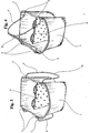
- La figure 1 est une vue de l'avant du seau avec les anses soulevées.
- La figure 2 est une vue en élévation du seau avec les anses rabattues, cette vue mettant en évidence la portion du fond rehaussée.
- La figure 3 est une vue en perspective, prise du haut, du seau avec ses anses rabattues et pourvu à l'intérieur du secteur qui sépare les deux bassins.
- La figure 4 est une vue en perspective similaire, prise du haut, du seau mais avec ses anses soulevées en appui l'une contre l'autre à l'endroit de leurs sommets.
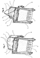
- La figure 5 est une we en perspective du seau monté sur un chariot pourvu de flancs. Les anses du seau sont rabattues et se trouvent à l'extérieur des flancs du chariot, dans une position sensiblement parallèle à ces flancs. Dans cette position, il est possible de monter un appareil d'essorage sur la traverse supérieure du chariot proche de la paroi du seau en appui sur le chariot.
- La figure 6 est une vue en perspective du seau monté sur un chariot pourvu de flancs. Les anses du seau sont représentées soulevées. La partie rehaussée du fond du seau est en appui sur une traverse antérieure du chariot, tandis que la partie restante du fond est en appui sur le plan porteur du chariot.
- La figure 7 est une vue en perspective, prise du haut et de l'arrière, du même chariot et du seau monté sur celui-ci. Les anses sont rabattues en appui sur l'extérieur des flancs du chariot.
- La figure 8 est une vue en perspective, prise du haut et de l'arrière, du même chariot et du seau monté sur celui-ci. Les anses du seau sont soulevées et en appui l'une contre l'autre à l'endroit de leurs sommets.
- La figure 9 est une vue de l'avant du chariot avec le seau à anses soulevées.
- La figure 10 est une vue de l'arrière du chariot avec le seau à anses soulevées.
- La figure 11 est une vue en perspective, prise d'un côté et partiellement de l'arrière, du même chariot et du seau monté sur celui-ci. Les anses du seau sont rabattues en appui sur l'extérieur des flancs du chariot.
- La figure 12 est une vue analogue à celle de la figure 11 mais prise du côté opposé du chariot.
- Figure 1 is a front view of the bucket with the handles raised.
- Figure 2 is an elevational view of the bucket with folded handles, this view highlighting the raised portion of the bottom.
- Figure 3 is a perspective view, taken from the top, of the bucket with its folded handles and provided inside the sector which separates the two basins.
- Figure 4 is a similar perspective view taken from the top of the bucket but with its handles lifted against each other at the place of their summits.
- Figure 5 is a perspective view of the bucket mounted on a carriage with flanks. The handles of the bucket are folded and are outside the sides of the carriage, in a position substantially parallel to these flanks. In this position, it is possible to mount a spinning device on the top rail of the carriage near the wall of the bucket resting on the carriage.
- Figure 6 is a perspective view of the bucket mounted on a carriage with sidewalls. The handles of the bucket are represented raised. The raised portion of the bottom of the bucket is supported on an anterior cross of the carriage, while the remaining portion of the bottom is supported on the carrier plane of the carriage.
- Figure 7 is a perspective view, taken from above and from the rear, of the same carriage and the bucket mounted thereon. The handles are folded in support on the outside of the sides of the carriage.
- Figure 8 is a perspective view, taken from above and from the rear, of the same carriage and the bucket mounted thereon. The handles of the bucket are raised and supported against each other at the place of their summits.
- Figure 9 is a front view of the cart with the bucket with raised handles.
- Figure 10 is a rear view of the cart with the bucket with raised handles.
- Figure 11 is a perspective view, taken from one side and partially from the rear, of the same carriage and the bucket mounted thereon. The handles of the bucket are folded in support on the outside of the sides of the carriage.
- Figure 12 is a view similar to that of Figure 11 but taken from the opposite side of the carriage.
Sur les différentes figures des dessins, on voit un seau 1 présentant un gradin 2 de rehaussement de la base du seau, dans la partie antérieure de celui-ci, ce gradin correspondant à la hauteur totale d'une traverse antérieure 8 d'un chariot 7. Le seau 1 comporte, sur son bord supérieur, des saillies 3 pour l'articulation de deux anses 4 du seau. Chaque anse 4 comporte un tronçon initial 5 qui forme un angle avec la partie restante de l'anse, de telle façon que, lorsque que le seau est monté sur le chariot, les anses s'étendent vers le bas en appui sur les faces externes des flancs du chariot. Le seau comporte un secteur interne 6 qui peut être fixe ou amovible et qui délimite deux bassins distincts du seau. Le chariot 7 comporte la traverse antérieure 8, surélevée par rapport à un plan porteur 13, des flancs 10, une traverse supérieure 9 sur laquelle peut être monté un appareil d'essorage, un compartiment 11 destiné à contenir des bouteilles ou des accessoires du chariot, une barrière 12 de délimitation du compartiment 11. Par ailleurs, les anses 4 du seau comportent chacune un sommet ou tronçon supérieur s'étendant pratiquement horizontalement.In the various figures of the drawings, there is shown a
D'après la description précédente, on peut voir l'importance de l'invention en ce qui concerne la structure du seau avec le gradin de rehaussement antérieur du fond, ses anses de forme particulière qui permettent d'utiliser le seau tel quel en pouvant le monter sur un chariot pourvu de flancs, ce seau étant en mesure, une fois complété avec un secteur interne définissant deux bassins distincts, d'assumer les mêmes fonctions qu'avec deux seaux distincts séparés montés sur un chariot ayant un encombrement double.From the foregoing description, it is possible to see the importance of the invention with regard to the bucket structure with the step of anterior enhancement of the bottom, its handles of particular shape which make it possible to use the bucket as it can by the bucket is able, when completed with an inner sector defining two separate basins, to perform the same functions as with two separate separate buckets mounted on a carriage having a double footprint.
Claims (5)
- A cleaning bucket equipped with handles (4) comprising initial sections (5) and a central part (14), which bucket (1) has handles (4) that may be extended downward when the bucket is mounted on a trolley (7) with sides (10), due to the shape of the initial sections (5) of these handles (4),
characterized in that the handles (4) of the bucket, mounted on a trolley (7) with sides (10), extend on the outer face of the sides (10), parallel to the latter and practically in contact with them, and downward with minimal bulk. - The cleaning bucket equipped with handles (4) according to claim 1, characterized in that its positioning onto the trolley (7) or its removal from this trolley (7) is facilitated thanks to the configuration of the tops of the handles (4) comprising an appropriate curvilinear section (14), practically horizontal, that allows the bucket to be raised by being inclined in one direction or the other, by gripping the handles (4) with one hand placed in front or in back with relation to the central part (14) of this section.
- The cleaning bucket equipped with handles (4) according to claim 1, characterized in that the shape of the handles (4) that allows their application on the sides of the bucket that are contiguous with the sides (10) of the trolley (7) leaves the side that may be affected by the mounting of a wringing apparatus completely available.
- The cleaning bucket equipped with handles (4) according to claim 1, characterized in that the particular shape of the handles (4) that allows their application on the sides of the bucket that are contiguous with the sides (10) of the trolley (7) leaves the front side that may be extended on alternate points in front beyond the plane projection of the trolley completely available.
- The cleaning bucket equipped with handles (4) according to claim 1, characterized in that the shape of the top of the handles (4), with an extended curvilinear section (14), substantially horizontal, allows the reduced base of the bucket (1) to be inserted in the trolley (7) compartment delimited in front by a retaining bar (8).
Applications Claiming Priority (2)
| Application Number | Priority Date | Filing Date | Title |
|---|---|---|---|
| LU90331A LU90331B1 (en) | 1998-12-18 | 1998-12-18 | Cleaning bucket with specially shaped handles |
| LU90331 | 1998-12-18 |
Publications (2)
| Publication Number | Publication Date |
|---|---|
| EP1013214A1 EP1013214A1 (en) | 2000-06-28 |
| EP1013214B1 true EP1013214B1 (en) | 2006-02-22 |
Family
ID=19731791
Family Applications (1)
| Application Number | Title | Priority Date | Filing Date |
|---|---|---|---|
| EP99204189A Expired - Lifetime EP1013214B1 (en) | 1998-12-18 | 1999-12-07 | Cleaning bucket with handles of a particular shape |
Country Status (7)
| Country | Link |
|---|---|
| EP (1) | EP1013214B1 (en) |
| AT (1) | ATE318102T1 (en) |
| BR (1) | BR9907428A (en) |
| DE (1) | DE69929932T2 (en) |
| ES (1) | ES2258836T3 (en) |
| LU (1) | LU90331B1 (en) |
| PT (1) | PT1013214E (en) |
Families Citing this family (6)
| Publication number | Priority date | Publication date | Assignee | Title |
|---|---|---|---|---|
| ITPD20020189A1 (en) | 2002-07-12 | 2004-01-12 | Filmop Srl | DEVICES FOR DISENGAGEMENT OF THE DIVIDING WALL REMOVABLE FROM THE COUPLING FOR THE BASINS OR BUCKETS IN WHICH IT IS INSERTED. |
| GB0322157D0 (en) * | 2003-09-22 | 2003-10-22 | Numatic Int Ltd | Bucket for mopping |
| ES2542515T3 (en) | 2008-11-05 | 2015-08-06 | Ecolab Inc. | Cleaning cart |
| DE102009043686B4 (en) * | 2009-10-01 | 2013-10-10 | Carl Freudenberg Kg | mop bucket |
| DE102015014122B3 (en) * | 2015-11-04 | 2017-02-09 | Carl Freudenberg Kg | bucket |
| DE102018111876B4 (en) | 2018-05-17 | 2020-01-23 | Leifheit Ag | bucket |
Family Cites Families (4)
| Publication number | Priority date | Publication date | Assignee | Title |
|---|---|---|---|---|
| DE8606934U1 (en) * | 1986-03-13 | 1986-04-30 | Breest, Rudolf, 8000 München | Trolley for holding at least one bucket |
| DE9206733U1 (en) * | 1992-05-19 | 1992-07-30 | Vermop Salmon Gmbh, 6980 Wertheim, De | |
| ES2099035B1 (en) * | 1995-10-10 | 1998-01-01 | Munoz De Arenillas Y Merino Fr | IMPROVEMENTS INTRODUCED IN FRIEGASUELOS DEVICES. |
| LU88745A1 (en) * | 1996-04-18 | 1996-10-04 | Az Int Sa | Cleaning trolley usable more particularly for transporting buckets and supporting a wringer made entirely of one-piece resinous material |
-
1998
- 1998-12-18 LU LU90331A patent/LU90331B1/en active
-
1999
- 1999-12-07 AT AT99204189T patent/ATE318102T1/en not_active IP Right Cessation
- 1999-12-07 DE DE69929932T patent/DE69929932T2/en not_active Expired - Fee Related
- 1999-12-07 PT PT99204189T patent/PT1013214E/en unknown
- 1999-12-07 ES ES99204189T patent/ES2258836T3/en not_active Expired - Lifetime
- 1999-12-07 EP EP99204189A patent/EP1013214B1/en not_active Expired - Lifetime
- 1999-12-15 BR BR9907428-1A patent/BR9907428A/en not_active Application Discontinuation
Also Published As
| Publication number | Publication date |
|---|---|
| ATE318102T1 (en) | 2006-03-15 |
| ES2258836T3 (en) | 2006-09-01 |
| DE69929932T2 (en) | 2006-11-09 |
| BR9907428A (en) | 2000-09-05 |
| DE69929932D1 (en) | 2006-04-27 |
| EP1013214A1 (en) | 2000-06-28 |
| PT1013214E (en) | 2006-06-30 |
| LU90331B1 (en) | 2001-12-06 |
Similar Documents
| Publication | Publication Date | Title |
|---|---|---|
| FR2713912A1 (en) | Device for collecting a dirty washing liquid and containing a liquid for soaking a mop or the like for hand washing floors or the like. | |
| FR2473871A1 (en) | REMOVABLE TOILET SEAT | |
| CH639622A5 (en) | BIN FOR PLANTS. | |
| EP1013214B1 (en) | Cleaning bucket with handles of a particular shape | |
| EP0910983B1 (en) | Wringer assembly comprising a wringer cup for a floorcloth centrally located on a bucket with two compartments | |
| EP0113260B1 (en) | Trolley, in particular for self-service shoppers | |
| CH657975A5 (en) | STORAGE AND EXPOSURE DEVICE. | |
| EP0028953A1 (en) | Water or sand box | |
| FR2530570A3 (en) | Nestable self-service trolley with crate holder. | |
| WO2000014373A1 (en) | Portable support structure useful as ladder or stepladder | |
| FR2561685A1 (en) | SINK WITH VACUUM-GARMENTS INCORPORATED | |
| FR2699085A1 (en) | Device for cleaning golf clubs. | |
| FR2681048A1 (en) | Stacking and nesting goods-handling tub with evacuation of any liquid which it may contain to the exterior | |
| FR2523060A1 (en) | TROLLEY WITH GOODS HOLDER | |
| LU87906A1 (en) | TOOL BOX AND CONTAINER ASSEMBLY | |
| FR2492769A1 (en) | East pour canister with integral spout - has flexible spout with hooks for locking along top and integral vertical handle | |
| WO1998011772A1 (en) | Device for containing and hanging up a material load, for instance a flower pot | |
| FR2492768A1 (en) | Sectional stackable trolley for shop - uses bent straps projecting up from top ends of side panels to house into corners of base of superposed trolley | |
| FR2792819A1 (en) | DISHWASHING MACHINE EQUIPPED WITH REMOVABLE BASKETS | |
| FR2787052A1 (en) | Carriage with wheels for garden tools has vertical square-section column accommodating bin and having flanges at top and bottom with spring clips in grooves and sockets holding tools | |
| FR2556200A1 (en) | HOUSEHOLD BASKETS SUITABLE FOR LARGE AREA STORAGE HANDLERS AND TROLLEYS | |
| EP1036723B1 (en) | Device adapted to be mounted on a trolley comprising buckets and a wringing mechanism | |
| WO1998024357A1 (en) | Dishwasher basket | |
| EP0057800A1 (en) | Pivoting shelf with a locking device in a raised position, especially for foldable containers and for restocking trolleys in shops | |
| FR2545405A1 (en) | Raising support device for a two-wheeled vehicle |
Legal Events
| Date | Code | Title | Description |
|---|---|---|---|
| PUAI | Public reference made under article 153(3) epc to a published international application that has entered the european phase |
Free format text: ORIGINAL CODE: 0009012 |
|
| AK | Designated contracting states |
Kind code of ref document: A1 Designated state(s): AT BE CH CY DE DK ES FI FR GB GR IE IT LI LU MC NL PT SE |
|
| AX | Request for extension of the european patent |
Free format text: AL;LT;LV;MK;RO;SI |
|
| 17P | Request for examination filed |
Effective date: 20001009 |
|
| RIN1 | Information on inventor provided before grant (corrected) |
Inventor name: L'INVENTEUR A RENONCE A SA DESIGNATION. |
|
| AKX | Designation fees paid |
Free format text: AT BE CH CY DE DK ES FI FR GB GR IE IT LI LU MC NL PT SE |
|
| AXX | Extension fees paid |
Free format text: SI PAYMENT 20001009 |
|
| RAP1 | Party data changed (applicant data changed or rights of an application transferred) |
Owner name: L&M SERVICES B.V. |
|
| RAP1 | Party data changed (applicant data changed or rights of an application transferred) |
Owner name: FILMOP S.R.L. |
|
| 17Q | First examination report despatched |
Effective date: 20050126 |
|
| GRAP | Despatch of communication of intention to grant a patent |
Free format text: ORIGINAL CODE: EPIDOSNIGR1 |
|
| GRAS | Grant fee paid |
Free format text: ORIGINAL CODE: EPIDOSNIGR3 |
|
| GRAA | (expected) grant |
Free format text: ORIGINAL CODE: 0009210 |
|
| AK | Designated contracting states |
Kind code of ref document: B1 Designated state(s): AT BE CH CY DE DK ES FI FR GB GR IE IT LI LU MC NL PT SE |
|
| AX | Request for extension of the european patent |
Extension state: SI |
|
| PG25 | Lapsed in a contracting state [announced via postgrant information from national office to epo] |
Ref country code: NL Free format text: LAPSE BECAUSE OF FAILURE TO SUBMIT A TRANSLATION OF THE DESCRIPTION OR TO PAY THE FEE WITHIN THE PRESCRIBED TIME-LIMIT Effective date: 20060222 Ref country code: IE Free format text: LAPSE BECAUSE OF FAILURE TO SUBMIT A TRANSLATION OF THE DESCRIPTION OR TO PAY THE FEE WITHIN THE PRESCRIBED TIME-LIMIT Effective date: 20060222 Ref country code: FI Free format text: LAPSE BECAUSE OF FAILURE TO SUBMIT A TRANSLATION OF THE DESCRIPTION OR TO PAY THE FEE WITHIN THE PRESCRIBED TIME-LIMIT Effective date: 20060222 Ref country code: AT Free format text: LAPSE BECAUSE OF FAILURE TO SUBMIT A TRANSLATION OF THE DESCRIPTION OR TO PAY THE FEE WITHIN THE PRESCRIBED TIME-LIMIT Effective date: 20060222 |
|
| REG | Reference to a national code |
Ref country code: GB Ref legal event code: FG4D Free format text: NOT ENGLISH |
|
| REG | Reference to a national code |
Ref country code: CH Ref legal event code: EP |
|
| REG | Reference to a national code |
Ref country code: IE Ref legal event code: FG4D Free format text: LANGUAGE OF EP DOCUMENT: FRENCH |
|
| REF | Corresponds to: |
Ref document number: 69929932 Country of ref document: DE Date of ref document: 20060427 Kind code of ref document: P |
|
| PG25 | Lapsed in a contracting state [announced via postgrant information from national office to epo] |
Ref country code: SE Free format text: LAPSE BECAUSE OF FAILURE TO SUBMIT A TRANSLATION OF THE DESCRIPTION OR TO PAY THE FEE WITHIN THE PRESCRIBED TIME-LIMIT Effective date: 20060522 Ref country code: DK Free format text: LAPSE BECAUSE OF FAILURE TO SUBMIT A TRANSLATION OF THE DESCRIPTION OR TO PAY THE FEE WITHIN THE PRESCRIBED TIME-LIMIT Effective date: 20060522 |
|
| GBT | Gb: translation of ep patent filed (gb section 77(6)(a)/1977) |
Effective date: 20060524 |
|
| REG | Reference to a national code |
Ref country code: PT Ref legal event code: SC4A Effective date: 20060508 |
|
| NLV1 | Nl: lapsed or annulled due to failure to fulfill the requirements of art. 29p and 29m of the patents act | ||
| REG | Reference to a national code |
Ref country code: ES Ref legal event code: FG2A Ref document number: 2258836 Country of ref document: ES Kind code of ref document: T3 |
|
| REG | Reference to a national code |
Ref country code: IE Ref legal event code: FD4D |
|
| PLBE | No opposition filed within time limit |
Free format text: ORIGINAL CODE: 0009261 |
|
| STAA | Information on the status of an ep patent application or granted ep patent |
Free format text: STATUS: NO OPPOSITION FILED WITHIN TIME LIMIT |
|
| PG25 | Lapsed in a contracting state [announced via postgrant information from national office to epo] |
Ref country code: MC Free format text: LAPSE BECAUSE OF NON-PAYMENT OF DUE FEES Effective date: 20061231 Ref country code: LI Free format text: LAPSE BECAUSE OF NON-PAYMENT OF DUE FEES Effective date: 20061231 Ref country code: CH Free format text: LAPSE BECAUSE OF NON-PAYMENT OF DUE FEES Effective date: 20061231 Ref country code: BE Free format text: LAPSE BECAUSE OF NON-PAYMENT OF DUE FEES Effective date: 20061231 |
|
| 26N | No opposition filed |
Effective date: 20061123 |
|
| PG25 | Lapsed in a contracting state [announced via postgrant information from national office to epo] |
Ref country code: DE Free format text: LAPSE BECAUSE OF NON-PAYMENT OF DUE FEES Effective date: 20070703 |
|
| REG | Reference to a national code |
Ref country code: CH Ref legal event code: PL |
|
| GBPC | Gb: european patent ceased through non-payment of renewal fee |
Effective date: 20061207 |
|
| PG25 | Lapsed in a contracting state [announced via postgrant information from national office to epo] |
Ref country code: PT Free format text: LAPSE BECAUSE OF NON-PAYMENT OF DUE FEES Effective date: 20070907 |
|
| REG | Reference to a national code |
Ref country code: PT Ref legal event code: MM4A Free format text: LAPSE DUE TO NON-PAYMENT OF FEES Effective date: 20070907 |
|
| REG | Reference to a national code |
Ref country code: FR Ref legal event code: ST Effective date: 20070831 |
|
| PG25 | Lapsed in a contracting state [announced via postgrant information from national office to epo] |
Ref country code: GB Free format text: LAPSE BECAUSE OF NON-PAYMENT OF DUE FEES Effective date: 20061207 |
|
| BERE | Be: lapsed |
Owner name: *FILMOP S.R.L. Effective date: 20061231 |
|
| PGFP | Annual fee paid to national office [announced via postgrant information from national office to epo] |
Ref country code: IT Payment date: 20071213 Year of fee payment: 9 |
|
| REG | Reference to a national code |
Ref country code: ES Ref legal event code: FD2A Effective date: 20061209 |
|
| PG25 | Lapsed in a contracting state [announced via postgrant information from national office to epo] |
Ref country code: FR Free format text: LAPSE BECAUSE OF NON-PAYMENT OF DUE FEES Effective date: 20070102 Ref country code: ES Free format text: LAPSE BECAUSE OF NON-PAYMENT OF DUE FEES Effective date: 20061209 |
|
| PG25 | Lapsed in a contracting state [announced via postgrant information from national office to epo] |
Ref country code: LU Free format text: LAPSE BECAUSE OF NON-PAYMENT OF DUE FEES Effective date: 20061207 |
|
| PG25 | Lapsed in a contracting state [announced via postgrant information from national office to epo] |
Ref country code: CY Free format text: LAPSE BECAUSE OF FAILURE TO SUBMIT A TRANSLATION OF THE DESCRIPTION OR TO PAY THE FEE WITHIN THE PRESCRIBED TIME-LIMIT Effective date: 20060222 |
|
| PGFP | Annual fee paid to national office [announced via postgrant information from national office to epo] |
Ref country code: GR Payment date: 20061231 Year of fee payment: 8 |
|
| PG25 | Lapsed in a contracting state [announced via postgrant information from national office to epo] |
Ref country code: GR Free format text: LAPSE BECAUSE OF NON-PAYMENT OF DUE FEES Effective date: 20071231 |
|
| PG25 | Lapsed in a contracting state [announced via postgrant information from national office to epo] |
Ref country code: IT Free format text: LAPSE BECAUSE OF NON-PAYMENT OF DUE FEES Effective date: 20081207 |