EP1012652B1 - Dispositif de raccordement de cables de fibres optiques - Google Patents
Dispositif de raccordement de cables de fibres optiques Download PDFInfo
- Publication number
- EP1012652B1 EP1012652B1 EP97947132A EP97947132A EP1012652B1 EP 1012652 B1 EP1012652 B1 EP 1012652B1 EP 97947132 A EP97947132 A EP 97947132A EP 97947132 A EP97947132 A EP 97947132A EP 1012652 B1 EP1012652 B1 EP 1012652B1
- Authority
- EP
- European Patent Office
- Prior art keywords
- longitudinal support
- bearing surface
- support
- upper bearing
- longitudinal
- Prior art date
- Legal status (The legal status is an assumption and is not a legal conclusion. Google has not performed a legal analysis and makes no representation as to the accuracy of the status listed.)
- Expired - Lifetime
Links
Images




Classifications
-
- G—PHYSICS
- G02—OPTICS
- G02B—OPTICAL ELEMENTS, SYSTEMS OR APPARATUS
- G02B6/00—Light guides; Structural details of arrangements comprising light guides and other optical elements, e.g. couplings
- G02B6/44—Mechanical structures for providing tensile strength and external protection for fibres, e.g. optical transmission cables
- G02B6/4439—Auxiliary devices
- G02B6/444—Systems or boxes with surplus lengths
- G02B6/4441—Boxes
- G02B6/4446—Cable boxes, e.g. splicing boxes with two or more multi fibre cables
-
- G—PHYSICS
- G02—OPTICS
- G02B—OPTICAL ELEMENTS, SYSTEMS OR APPARATUS
- G02B6/00—Light guides; Structural details of arrangements comprising light guides and other optical elements, e.g. couplings
- G02B6/44—Mechanical structures for providing tensile strength and external protection for fibres, e.g. optical transmission cables
- G02B6/4439—Auxiliary devices
- G02B6/4471—Terminating devices ; Cable clamps
-
- G—PHYSICS
- G02—OPTICS
- G02B—OPTICAL ELEMENTS, SYSTEMS OR APPARATUS
- G02B6/00—Light guides; Structural details of arrangements comprising light guides and other optical elements, e.g. couplings
- G02B6/44—Mechanical structures for providing tensile strength and external protection for fibres, e.g. optical transmission cables
- G02B6/4439—Auxiliary devices
- G02B6/444—Systems or boxes with surplus lengths
- G02B6/4441—Boxes
- G02B6/4442—Cap coupling boxes
Definitions
- the present invention relates to a device for connecting fiber optic cables.
- Fiber optic cable connection devices are used in particular for long distance lines buried, joining end to end sections of cables determined length.
- connection device is housed in a housing waterproof protection and is generally filled with a pressurized gas which prevents the introduction of dust inside the housing.
- the fibers optics are connected two by two using splices which are grouped side by side in one or more cassettes.
- the lengths of fiber reserves necessary for the making splices are then rolled up on themselves then clamped in the cassette (s) in the immediate vicinity of the splices on the one hand to prevent them from getting tangled up with each other and on the other hand to control the radius of curvature.
- each fiber must have a length determined before the sawing operation so that according to the final position of the splice in the cassette, the fiber loops can be arranged and restrained in an orderly fashion. This constitutes a first difficulty in implementing the device.
- connection device In the connection device according to the invention, the bare optical fibers undergo a minimum of stresses because they are only held at their two ends, namely at the entrance to the device when they enter the free space and on the sides of the longitudinal support just before reaching the elements individual connection.
- all the optical fibers from a same cable can have the same length, regardless of the element individual connection to which each fiber leads.
- the support longitudinal is mounted on a central leg around which the fibers optics curl up. This foot allows the lifting and rotation of the longitudinal support relative to the housing.
- connection device by slightly elevating the longitudinal support and turning it at 90 ° to the housing, the loops formed by the fibers optics in the space provided for this purpose constituting a reserve of length of fibers which allows this rotation.
- connection device it is understood that, thanks to the connection device according to the invention, you can easily modify a connection by moving the end of a fiber optic connection element individual to another, or swap the ends of two fibers optics without any difficulty.
- the device according to the invention makes it possible to minimize the necessary manipulations the placement of fibers.
- the device according to the invention is much more practical to implement as connecting devices in which, as is generally recommended, the reserve lengths of the optical fibers are coiled in cassettes and clamps in several places to follow an imposed route.
- the longitudinal support has a cross section substantially ovoid.
- said longitudinal support has guides on its sides, on both sides of its face upper bearing connection elements, each guide leading each fiber radially from the lower edge of the flank to the end of an individual connecting element.
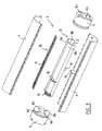
- the device 1 shown in the drawing is housed in a cylindrical housing 2, with a longitudinal axis parallel to that of device, consisting of a base 3 and a cover 4 which can be assembled according to two opposite generators of the housing.
- the base 3 of the housing is itself constituted by a base lower 5 and by two disc-shaped end caps 6.
- Each end piece 6 has four holes 6 a , 6 b , 6 c , 6 d which allow the introduction of four cables inside the housing.
- the housing internally delimits a volume 7 in which is housed The device 1 according to the invention.
- This device 1 comprises a longitudinal support 8, of oval cross section, comprising two sides 8 b and an upper surface 8 a .
- the upper surface 8 a is substantially flat and is in the form of a rectangular surface.
- the lateral flanks 8 b are convex, their section being circular, and extend from the upper surface 8 a to which they are connected without any edge, to below said upper surface 8 a .
- the radius of curvature of the lateral flanks is greater than or equal to the minimum radius of curvature of the fibers of the cables to be connected.
- the support is open inferiorly and delimits, in particular between the upper surface 8 a and 8 b the lateral flanks, a clearance 9 for the optical fibers.
- This free space 9 is bounded below by the base 3 of the housing having a diameter sufficient to receive the lower edges of the lateral sides 8b, so that said free space 9 is closed when the carrier 8 is placed in the base, only two longitudinal slots 17 formed between the lateral sides 8b and the side walls of the base component of the passages between said gap 9 and the top of the support 8.
- slots 17 allow optical fibers to pass directly from free space 9 to connecting elements.
- a strip 10 of individual connecting elements 11 parallel is fixed on the upper face of the upper surface 8 a of the longitudinal support.
- Each individual connecting element 11 is presented transversely to the longitudinal support with one end directed towards each of its sides 8b .
- the sides 8b of the longitudinal support include guides 12 for the optical fibers in the form of grooves extending radially, that is to say in perpendicular planes to the longitudinal axis of the support.
- These guides 12 conduct each fiber radially from the lower edge of a sidewall to the end of an individual element 11 and thus ensure the maintenance of the fibers against one of the sides of the support.
- the support 8 has a central stud 13 opposite its face upper, which stud coincides with a foot 14 provided on the base 5 of the case.
- the stud 13 and the foot 14 allow the positioning of the longitudinal support 8 in the housing and the rotation of said longitudinal support relative to the housing when said support is slightly raised, as seen in the section of figure 6.
- optical fiber 15 has been shown through the introduction orifices 6 c and 6 d .
- connection elements can be devices such as that described in the French patent application No. 95 07987 of the plaintiff.
Landscapes
- Physics & Mathematics (AREA)
- General Physics & Mathematics (AREA)
- Optics & Photonics (AREA)
- Light Guides In General And Applications Therefor (AREA)
- Mechanical Coupling Of Light Guides (AREA)
Description
- un support longitudinal comportant une portée supérieure sensiblement plane s'étendant longitudinalement et deux flancs latéraux s'étendant longitudinalement de part et d'autre de cette portée supérieure en direction du dessous de ladite portée supérieure,
- une pluralité d'éléments individuels de raccordement de fibres optiques deux à deux, chaque élément de raccordement étant susceptible d'être disposé transversalement sur la face supérieure de la portée supérieure du support longitudinal,
- un espace libre ménagé dans le support longitudinal et partiellement délimité par ce dernier, espace libre dans lequel des fibres optiques sont destinées à pénétrer et à se lover librement puis à rejoindre directement un élément individuel de raccordement fixé sur la face supérieure de la portée supérieure du support longitudinal.
- la figure 1 est une vue en perspective d'un boítier muni d'un dispositif de raccordement selon un mode de réalisation de l'invention,
- la figure 2 est une vue éclatée du dispositif de la figure 1,
- la figure 3 est une autre vue éclatée du même dispositif,
- la figure 4 représente le support longitudinal en perspective,
- la figure 5 est une vue en coupe selon V-V de la figure 7, le bottier étant fermé,
- la figure 6 est une section selon VI-VI de la figure 7, le boítier étant ouvert et le support longitudinal relevé, et
- la figure 7 est une vue schématique de dessus du dispositif après introduction et agencement des brins de deux câbles.
Claims (4)
- Dispositif de raccordement d'au moins deux câbles de fibres optiques, comportant :un support longitudinal (8) comportant une portée supérieure (8a) sensiblement plane s'étendant longitudinalement et deux flancs latéraux convexes (8b) s'étendant longitudinalement de part et d'autre de cette portée supérieure en direction du dessous de ladite portée supérieure, le rayon de courbure de la section transversale de chaque flanc étant au moins égal au rayon de courbure minimal des fibres optiques des câbles à raccorder,une pluralité d'éléments individuels de raccordement (11) de fibres optiques (15) deux à deux, chaque élément de raccordement (11) étant disposé transversalement sur la face supérieure de la portée supérieure (8a) du support longitudinal,un espace libre,(9) ouvert à ses deux extrémités ménagé dans le support longitudinal et partiellement délimité par la portée supérieure et les deux flancs latéraux de ce dernier, etun boitier (2) cylindrique recevant ledit support longitudinal, ledit boítier cylindrique (2) comportant à ses deux extrémités des entrées (6a, 6b, 6c, 6d) pour les câbles débouchant dans ledit espace libre (9) ménage dans ledit support longitudinal (8), ledit boítier cylindrique se composant d'un couvercle (4) et d'une embase (3) assemblés selon deux génératrices opposées du boitier, l'embase (3) présentant un diamètre suffisant pour recevoir les bords inférieurs des flancs latéraux (8b) du support mis en place dans l'embase avec son axe longitudinal parallèle à celui du boítier, de sorte que l'espace libre (9) est refermé par l'embase lorsque le support (8) est mis en place dans cette dernière et que seules deux fentes longitudinales (17) sont formées entre les flancs latéraux (8b) et les parois latérales de l'embase et constituent des passages pour les fibres entre ledit espace libre et le dessus du support, les fibres optiques (15) issues des câbles étant destinées à pénétrer dans ledit espace libre (9) dans lequel elles sont destinées à se lover librement puis à rejoindre directement, via l'un desdits passages longitudinaux (17) entre l'espace libre et le dessus du support un élément individuel de raccordement (11) fixé sur la face supérieure de la portée supérieure (8a) du support longitudinal (8) en étant maintenues contre la face externe du flanc correspondant dudit support longitudinal.
- Dispositif selon la revendication 1, caractérisé par le fait que le support longitudinal (8) est monté sur un pied central (13) autour duquel les fibres optiques (15) sont destinées à lover et qui permet le relèvement et la rotation du support longitudinal (8) par rapport au boítier.
- Dispositif selon l'une quelconque des revendications 1 et 2, caractérisé par le fait que le support longitudinal (8) présente une section transversale sensiblement ovoïdale, la portée supérieure (8a) se présentant sous la forme d'une surface rectangulaire et les flancs latéraux (8b) ayant une section circulaire et s'étendant depuis la portée supérieure (8a), à laquelle ils se raccordent sans arête, jusqu'en dessous de ladite portée supérieure.
- Dispositif selon l'une quelconque des revendications 1 à 3, caractérisé par le fait que le support longitudinal (8) est muni de guides transversaux (12) sur la face externe de ses flancs latéraux, de part et d'autre de sa portée supérieure, portant les éléments de raccordement, chaque guide transversal conduisant circonférentiellement chaque fibre du bord inférieur du flanc à l'extrémité d'un élément individuel de raccordement (11).
Applications Claiming Priority (3)
| Application Number | Priority Date | Filing Date | Title |
|---|---|---|---|
| FR9614375 | 1996-11-25 | ||
| FR9614375A FR2756382B1 (fr) | 1996-11-25 | 1996-11-25 | Dispositif de raccordement de cables |
| PCT/FR1997/002122 WO1998023987A1 (fr) | 1996-11-25 | 1997-11-25 | Dispositif de raccordement de cables de fibres optiques |
Publications (2)
| Publication Number | Publication Date |
|---|---|
| EP1012652A1 EP1012652A1 (fr) | 2000-06-28 |
| EP1012652B1 true EP1012652B1 (fr) | 2002-12-18 |
Family
ID=9497968
Family Applications (1)
| Application Number | Title | Priority Date | Filing Date |
|---|---|---|---|
| EP97947132A Expired - Lifetime EP1012652B1 (fr) | 1996-11-25 | 1997-11-25 | Dispositif de raccordement de cables de fibres optiques |
Country Status (7)
| Country | Link |
|---|---|
| US (1) | US6217227B1 (fr) |
| EP (1) | EP1012652B1 (fr) |
| AU (1) | AU5229198A (fr) |
| DE (1) | DE69718070T2 (fr) |
| ES (1) | ES2190545T3 (fr) |
| FR (1) | FR2756382B1 (fr) |
| WO (1) | WO1998023987A1 (fr) |
Families Citing this family (1)
| Publication number | Priority date | Publication date | Assignee | Title |
|---|---|---|---|---|
| FR3120139B1 (fr) * | 2021-02-23 | 2023-11-24 | Omelcom | Boitier de raccordement avec un dispositif d’étanchéité pourvu d’une partie longitudinale |
Citations (3)
| Publication number | Priority date | Publication date | Assignee | Title |
|---|---|---|---|---|
| EP0213365A1 (fr) * | 1985-07-23 | 1987-03-11 | Alcatel Cable | Dispositif de branchement |
| EP0479226A1 (fr) * | 1990-10-04 | 1992-04-08 | MARS-ACTEL Société Anonyme dite: | Cassette de raccordement optique |
| EP0549963A2 (fr) * | 1991-12-30 | 1993-07-07 | Reichle + De-Massari AG Elektro-Ingenieure | Armoire de distribution des terminaux des câbles de fibres de verre |
Family Cites Families (9)
| Publication number | Priority date | Publication date | Assignee | Title |
|---|---|---|---|---|
| DE3006131C2 (de) * | 1980-02-19 | 1983-04-28 | AEG-Telefunken Nachrichtentechnik GmbH, 7150 Backnang | Spleißmuffe mit einer Aufnahmevorrichtung für Vorratslängen von Lichtwellenleiterkabeln |
| DE3217922A1 (de) * | 1981-05-19 | 1982-12-09 | Souriau & Cie | Verbinder fuer optische fasern |
| US5185845A (en) * | 1990-12-13 | 1993-02-09 | At&T Bell Laboratories | Optical fiber closure having enhanced storage capability |
| US5204927A (en) * | 1992-03-02 | 1993-04-20 | Polaroid Corporation | Method and apparatus for making a fiber optical coupler |
| FR2692732B1 (fr) * | 1992-06-19 | 1996-09-06 | Morizot Jean Guy | Dispositif de raccordement et de protection de cables. |
| US5278933A (en) * | 1992-06-30 | 1994-01-11 | Hunsinger Terrance D | Fiber optic splice organizer and associated method |
| US5323480A (en) * | 1992-11-25 | 1994-06-21 | Raychem Corporation | Fiber optic splice closure |
| US5793921A (en) * | 1995-03-20 | 1998-08-11 | Psi Telecommunications, Inc. | Kit and method for converting a conductive cable closure to a fiber optic cable closure |
| US5644671A (en) * | 1995-06-23 | 1997-07-01 | Preformed Line Products Company | Optical fiber spice case with cross connect feature |
-
1996
- 1996-11-25 FR FR9614375A patent/FR2756382B1/fr not_active Expired - Fee Related
-
1997
- 1997-11-25 DE DE69718070T patent/DE69718070T2/de not_active Expired - Fee Related
- 1997-11-25 EP EP97947132A patent/EP1012652B1/fr not_active Expired - Lifetime
- 1997-11-25 US US09/297,770 patent/US6217227B1/en not_active Expired - Fee Related
- 1997-11-25 WO PCT/FR1997/002122 patent/WO1998023987A1/fr not_active Ceased
- 1997-11-25 AU AU52291/98A patent/AU5229198A/en not_active Abandoned
- 1997-11-25 ES ES97947132T patent/ES2190545T3/es not_active Expired - Lifetime
Patent Citations (3)
| Publication number | Priority date | Publication date | Assignee | Title |
|---|---|---|---|---|
| EP0213365A1 (fr) * | 1985-07-23 | 1987-03-11 | Alcatel Cable | Dispositif de branchement |
| EP0479226A1 (fr) * | 1990-10-04 | 1992-04-08 | MARS-ACTEL Société Anonyme dite: | Cassette de raccordement optique |
| EP0549963A2 (fr) * | 1991-12-30 | 1993-07-07 | Reichle + De-Massari AG Elektro-Ingenieure | Armoire de distribution des terminaux des câbles de fibres de verre |
Also Published As
| Publication number | Publication date |
|---|---|
| DE69718070T2 (de) | 2003-09-11 |
| FR2756382A1 (fr) | 1998-05-29 |
| AU5229198A (en) | 1998-06-22 |
| EP1012652A1 (fr) | 2000-06-28 |
| WO1998023987A1 (fr) | 1998-06-04 |
| DE69718070D1 (de) | 2003-01-30 |
| US6217227B1 (en) | 2001-04-17 |
| FR2756382B1 (fr) | 1998-12-24 |
| ES2190545T3 (es) | 2003-08-01 |
Similar Documents
| Publication | Publication Date | Title |
|---|---|---|
| EP0185923B1 (fr) | Support de raccordement de fibres optiques | |
| EP0538164B1 (fr) | Tête de câbles modulaire à fibres optiques de grande capacité | |
| EP1174747A1 (fr) | Support pour éléments filiformes de faible diamètre et faisceau d'éléments filiformes reliés entre eux par ce support | |
| EP1338910A1 (fr) | Cassette de lovage pour fibres optiques | |
| EP1581830A1 (fr) | Bobine de conditionnement avec dispositif de vidage de cable optique | |
| CA1251969A (fr) | Attenuateur optique variable pour couplage de fibres optiques | |
| EP0479226B1 (fr) | Cassette de raccordement optique | |
| FR2748576A1 (fr) | Dispositif pour lover des rubans ou des micro-gaines de fibres optiques, et leurs epissures ou coupleurs de raccordement | |
| FR2646928A1 (fr) | Module et boitier de raccordement de cables a fibres optiques | |
| EP0253728A1 (fr) | Dispositif de réserve pour fibres optiques | |
| FR2733843A1 (fr) | Dispositif organiseur de connexion de cables a fibres optiques et boite de jonction de cables optiques | |
| EP0420721B1 (fr) | Procédé d'enroulement en double d'un câble ou analogue sur la surface externe d'un touret | |
| FR2579330A1 (fr) | Dispositif de raccordement et protection d'epissures de cables de ligne a fibres optiques et procede de mise en oeuvre | |
| EP0712018B1 (fr) | Cassette pour le logement et la protection d'une fibre optique et installation pour le stockage de fibres optiques | |
| WO1998023987A1 (fr) | Dispositif de raccordement de cables de fibres optiques | |
| EP1054279A1 (fr) | Boítier d'accès à une ou plusieurs fibres optiques dans un câble tendu | |
| FR2577688A1 (fr) | Repartiteur de fibres optiques | |
| EP0803753B1 (fr) | Dispositif d'aide pour l'intervention et le rangement des fibres d'un câble optique | |
| FR2814246A1 (fr) | Dispositif de rangement de surlongueurs de cables de fibres optiques | |
| FR2586827A1 (fr) | Dispositif pour la mise a la masse rapide d'un cable, tel qu'un cable optique. | |
| FR2694642A1 (fr) | Dispositif de raccordement d'au moins un câble de transmission à des équipements électroniques. | |
| FR2586822A1 (fr) | Dispositif de reserve de fibres optiques, utilisable notamment dans un repartiteur de fibres optiques. | |
| CA2248774C (fr) | Dispositif pour relier des conducteurs d'un cable de transport a des conducteurs d'un cable de distribution | |
| FR2745393A1 (fr) | Dispositif de support d'epissures, notamment pour fibres ou modules optiques | |
| FR2750220A1 (fr) | Boitier de protection d'epissures, de repartition, de confinement et de stockage, des fibres optiques d'un cable de distribution |
Legal Events
| Date | Code | Title | Description |
|---|---|---|---|
| PUAI | Public reference made under article 153(3) epc to a published international application that has entered the european phase |
Free format text: ORIGINAL CODE: 0009012 |
|
| 17P | Request for examination filed |
Effective date: 19990520 |
|
| AK | Designated contracting states |
Kind code of ref document: A1 Designated state(s): BE DE ES FR IT |
|
| 17Q | First examination report despatched |
Effective date: 20010515 |
|
| GRAG | Despatch of communication of intention to grant |
Free format text: ORIGINAL CODE: EPIDOS AGRA |
|
| GRAG | Despatch of communication of intention to grant |
Free format text: ORIGINAL CODE: EPIDOS AGRA |
|
| GRAH | Despatch of communication of intention to grant a patent |
Free format text: ORIGINAL CODE: EPIDOS IGRA |
|
| GRAH | Despatch of communication of intention to grant a patent |
Free format text: ORIGINAL CODE: EPIDOS IGRA |
|
| GRAA | (expected) grant |
Free format text: ORIGINAL CODE: 0009210 |
|
| RAP1 | Party data changed (applicant data changed or rights of an application transferred) |
Owner name: RADIALL |
|
| AK | Designated contracting states |
Kind code of ref document: B1 Designated state(s): BE DE ES FR IT |
|
| RAP2 | Party data changed (patent owner data changed or rights of a patent transferred) |
Owner name: POUYET S.A. |
|
| REF | Corresponds to: |
Ref document number: 69718070 Country of ref document: DE Kind code of ref document: P Date of ref document: 20030130 |
|
| REG | Reference to a national code |
Ref country code: ES Ref legal event code: FG2A Ref document number: 2190545 Country of ref document: ES Kind code of ref document: T3 |
|
| PLBE | No opposition filed within time limit |
Free format text: ORIGINAL CODE: 0009261 |
|
| STAA | Information on the status of an ep patent application or granted ep patent |
Free format text: STATUS: NO OPPOSITION FILED WITHIN TIME LIMIT |
|
| PG25 | Lapsed in a contracting state [announced via postgrant information from national office to epo] |
Ref country code: ES Free format text: LAPSE BECAUSE OF NON-PAYMENT OF DUE FEES Effective date: 20031126 |
|
| PG25 | Lapsed in a contracting state [announced via postgrant information from national office to epo] |
Ref country code: BE Free format text: LAPSE BECAUSE OF NON-PAYMENT OF DUE FEES Effective date: 20031130 |
|
| 26N | No opposition filed |
Effective date: 20030919 |
|
| BERE | Be: lapsed |
Owner name: S.A. *POUYET Effective date: 20031130 |
|
| PG25 | Lapsed in a contracting state [announced via postgrant information from national office to epo] |
Ref country code: DE Free format text: LAPSE BECAUSE OF NON-PAYMENT OF DUE FEES Effective date: 20040602 |
|
| PG25 | Lapsed in a contracting state [announced via postgrant information from national office to epo] |
Ref country code: FR Free format text: LAPSE BECAUSE OF NON-PAYMENT OF DUE FEES Effective date: 20040730 |
|
| REG | Reference to a national code |
Ref country code: FR Ref legal event code: ST |
|
| REG | Reference to a national code |
Ref country code: ES Ref legal event code: FD2A Effective date: 20031126 |
|
| PG25 | Lapsed in a contracting state [announced via postgrant information from national office to epo] |
Ref country code: IT Free format text: LAPSE BECAUSE OF NON-PAYMENT OF DUE FEES;WARNING: LAPSES OF ITALIAN PATENTS WITH EFFECTIVE DATE BEFORE 2007 MAY HAVE OCCURRED AT ANY TIME BEFORE 2007. THE CORRECT EFFECTIVE DATE MAY BE DIFFERENT FROM THE ONE RECORDED. Effective date: 20051125 |