EP1012406B1 - An element for forming ground covering, restraining and reinforcing structures, particularly for forming retaining walls - Google Patents
An element for forming ground covering, restraining and reinforcing structures, particularly for forming retaining walls Download PDFInfo
- Publication number
- EP1012406B1 EP1012406B1 EP98912384A EP98912384A EP1012406B1 EP 1012406 B1 EP1012406 B1 EP 1012406B1 EP 98912384 A EP98912384 A EP 98912384A EP 98912384 A EP98912384 A EP 98912384A EP 1012406 B1 EP1012406 B1 EP 1012406B1
- Authority
- EP
- European Patent Office
- Prior art keywords
- restraining
- reinforcing
- intermediate portion
- netting
- positioning
- Prior art date
- Legal status (The legal status is an assumption and is not a legal conclusion. Google has not performed a legal analysis and makes no representation as to the accuracy of the status listed.)
- Expired - Lifetime
Links
Images

Classifications
-
- E—FIXED CONSTRUCTIONS
- E02—HYDRAULIC ENGINEERING; FOUNDATIONS; SOIL SHIFTING
- E02D—FOUNDATIONS; EXCAVATIONS; EMBANKMENTS; UNDERGROUND OR UNDERWATER STRUCTURES
- E02D29/00—Independent underground or underwater structures; Retaining walls
- E02D29/02—Retaining or protecting walls
- E02D29/0225—Retaining or protecting walls comprising retention means in the backfill
- E02D29/0241—Retaining or protecting walls comprising retention means in the backfill the retention means being reinforced earth elements
-
- E—FIXED CONSTRUCTIONS
- E02—HYDRAULIC ENGINEERING; FOUNDATIONS; SOIL SHIFTING
- E02D—FOUNDATIONS; EXCAVATIONS; EMBANKMENTS; UNDERGROUND OR UNDERWATER STRUCTURES
- E02D29/00—Independent underground or underwater structures; Retaining walls
- E02D29/02—Retaining or protecting walls
- E02D29/0258—Retaining or protecting walls characterised by constructional features
- E02D29/0266—Retaining or protecting walls characterised by constructional features made up of preformed elements
-
- E—FIXED CONSTRUCTIONS
- E02—HYDRAULIC ENGINEERING; FOUNDATIONS; SOIL SHIFTING
- E02D—FOUNDATIONS; EXCAVATIONS; EMBANKMENTS; UNDERGROUND OR UNDERWATER STRUCTURES
- E02D2200/00—Geometrical or physical properties
- E02D2200/13—Geometrical or physical properties having at least a mesh portion
-
- E—FIXED CONSTRUCTIONS
- E02—HYDRAULIC ENGINEERING; FOUNDATIONS; SOIL SHIFTING
- E02D—FOUNDATIONS; EXCAVATIONS; EMBANKMENTS; UNDERGROUND OR UNDERWATER STRUCTURES
- E02D2300/00—Materials
- E02D2300/0004—Synthetics
- E02D2300/0006—Plastics
Definitions
- the invention relates to an element for forming ground covering, restraining and reinforcing structures, particularly for forming retaining walls, with the features of claim 1.
- the elements are such as to form a substantially Channel-shaped restraining element having, for its base and its top, the two end portions of the element which are disposed substantially parallel to one another and, for a substantially vertical or inclined restraining wall, the intermediate portion between the two end portions, the restraining element being filled with earth, stones or combinations of earth and stones, and several Channel-shaped restraining elements each formed by a continuous element being able to be laid on top of one another to form walls or the like.
- An element for forming ground covering, restraining, and reinforcing structures particularly for forming retaining walls, the element comprising a continuous panel of wire netting comprising at least a bottom portion, an intermediate front restraining portion, and a top end covering portion, these portions being delimited relative to one another by reinforcing bars which also define predetermined lines for the bending of the three portions relative to one another so as to form a substantially Channel-shaped restraining element, wherein at least one reinforcing bar is disposed on the intermediate portion which is to form the substantially vertical or inclined, visible front restraining wall.
- the object of the present invention is to devise a completely prefabricated element of the type described above so that it is possible, by means of inexpensive and relatively simple measures, to form structures such as walls or the like which are stronger and of more attractive appearance, particularly walls with surfaces having predetermined inclinations, without requiring operations to assemble the various components of the element in the place of use.
- the invention achieves the above-mentioned object by means of an element of the type described at the beginning, in which the intermediate portion which is to form the vertical or inclined, visible restraining wall has at least one, and preferably several, further reinforcing bars inserted in the mesh of the wire netting and extending parallel to one another and parallel to the delimiting bars between the intermediate portion and the two opposed portions which are to form the base and top of the Channel-shaped restraining or reinforcing structure.
- each bracket when the visible portion of the Channel-shaped restraining structure formed by the netting element has to have a predetermined inclination relative to a perfectly vertical orientation, at least one, preferably two, and possibly even several brackets may be associated with each netting element in order to support it and position it in the correct inclined position, each bracket having at least a first arm which is a reinforcing bar and supports the intermediate portion for forming the visible front wall of the restraining element and which has the corresponding inclination, and at least a second arm parallel to the portion constituting the base.
- the support and positioning brackets are preferably articulated to the front portion of the Channel-shaped element so as to be pivotable from a rest and storage position in which they are laid against the portion to which they are articulated and therefore extend parallel thereto, to an operative position in which they are arranged in a substantially raised and perpendicular position relative to the portion to which they are articulated.
- the brackets are advantageously formed with the shape of a right-angled triangle or a right-angled trapezium.
- a particular embodiment of the invention consists of the fact that the element comprises, in addition to the wire netting panel, a so-called geosynthetic fines-retainer, this layer being superimposed inside the wire netting panel which is to form the front of the restraining element.
- the geosynthetic layer is preferably constituted by a bio-matting of natural fibres or the like.
- the layer of natural fibres may advantageously be reinforced by a netting of plastics material.
- the geosynthetic layer is formed by a geo-matting of plastics material.
- the front portion of the Channel-shaped element is also reinforced by a further netting panel (of the double-twisted or electrically-welded type) connected to the Channel-shaped element by staples at the production stage and thus enclosing the geosynthetic layer between the panel and the Channel-shaped element.
- a further netting panel of the double-twisted or electrically-welded type
- the above-mentioned measures strengthen the restraining element formed by the netting element, at least on the visible front portion of any walling. This is ensured both by the reinforcing bars, and by the positioning and support brackets, as well as by the reinforcing panel.
- the brackets enable the portion which forms the visible front wall of the restraining element to be positioned precisely in a predetermined manner, producing retaining walls with predetermined and precise inclinations.
- the further reinforcing bars may possibly be used as intermediate predetermined bending hinges thus enabling visible front walls of different heights to be formed according to requirements.
- the brackets for supporting and positioning the portion which forms the visible front wall may also be replaceable or simply capable of being bent to height about predetermined bending hinges or the like.
- the various types of geosynthetic material allow the restraining element to be adapted to various conditions of use of the structures formed with the elements according to the invention and improve the restraining characteristics and the aesthetic appearance of the structures, as well as their durability.
- the element according to the invention can be folded at least partially onto itself to a storage or transportation position in which it has a minimal size vertically and in which it can be packed together with other elements, for example, in the form of a pack of elements laid on top of one another, bound and held together by heat-shrinkable film or the like.
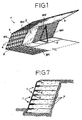
- an element 1 for forming ground covering, restraining and reinforcing structures, particularly for forming retaining walls is formed by a continuous wire-netting panel without any horizontal joints.
- the wire netting is of the double-twist type with a hexagonal mesh.
- the wire netting is advantageously galvanized and/or plastic-coated.
- the wire-netting panel is divided transversely into three regions comprising an intermediate portion 101 which is to form the visible front wall of the restraining element or structure and two end portions 201, 301 which are to form, respectively, a base and a top which, in the laid condition, extends at a certain distance from the base and is oriented substantially parallel thereto.
- the bend lines which divide the intermediate portion 101 from the end portions 201, 301 are defined by metal bars 2, 3 which have the function of reinforcing the netting and define predetermined bend lines.
- the intermediate portion 101 has further longitudinal bars 4, arranged parallel to the delimiting bars 2, 3 and preferably spaced apart uniformly.
- the intermediate bars are preferably spaced apart by a distance corresponding to one hexagonal mesh of the netting and, as well as reinforcing the intermediate portion 101 which constitutes the visible front wall of the restraining element, form further predetermined bend lines which enable visible front walls of different heights to be formed according to requirements.
- support and positioning brackets 5 are articulated to the intermediate portion 101 or can be articulated thereto by means of metal staples, rings or clips 105. These brackets are triangular and are pivotable from a rest or storage position in which they are folded against the inner side of the intermediate portion, to an operative position in which they are pivoted to a position substantially perpendicular to the intermediate portion 101.
- the two brackets 5 thus enable the intermediate portion 101 to be positioned and at the same time supported in the correct operative position when the netting panel is bent to form the restraining element.
- the two brackets 5 are superimposed on the intermediate portion 101, allowing it to be folded against the portion 301 which is to form the base, the element as a whole adopting a condition of minimum height.
- brackets 5 may be interchangeable for adaptation for bending at various heights along the intermediate bars 4, or may even be formed as adaptable elements, for example, so that they can be reduced in height by bending about predetermined hinges or bend lines, like the intermediate portion 101.
- a layer of restraining material with a considerably smaller mesh size is superimposed on the netting inside the element 1.
- This layer of restraining material is particularly suitable for use with mixed stone and earth fillings or with earth alone.
- the restraining layer, indicated 6, and otherwise known as a geosynthetic layer, may be formed of various materials according to the conditions of use.
- the fine-mesh restraining layer 6 is constituted by a so-called geo-matting of plastics material, preferably polypropylene.
- brackets 5 are advantageously mounted on a bracket-holder panel 401 which is also made, for example, of wire netting and which is fixed in position, superimposed on the intermediate portion 101 which is to form the front wall and bracket-holder panels of different sizes are provided according to which bending bar 3, 4 is selected.
- the fine-mesh restraining layer 6 is confined by the wire-netting panel 401 and is fixed to the Channel-shaped element by metal clips or the like.
- brackets are fixed to the reinforcing panel, and hence to the intermediate portion 101, with the interposition of the fine-mesh restraining layer 6 between them and the panel.
- Figures 2 to 6 show the ease with which the elements according to the invention can be laid. They are put in place and the unit constituted by the intermediate portion 101 and by the end portion 201 which forms the top of the Channel-shaped restraining element is raised, the two support and positioning brackets 5 being brought to the working position.
- the L-shaped element thus formed is then filled up to a predetermined level with earth, stones or mixtures of earth and stones (7, 7').
- the top end portion 201 is then bent against the top of the filling 7.
- the bottom end portion 301 of a further element laid in the same manner as described above, may be supported and fixed on this top portion by suitable fastenings with staples. Walls such as that indicated in Figure 7 can be formed by several elements laid on top of one another as described.
- elements having support and positioning brackets 5 of different shapes may be used so as to give the intermediate portion 101 a different inclination.
- the entire space defined by the element 1 bent to form a Channel-shaped restraining element may simply be filled with earth, or the filling in the head region directly adjacent the visible front wall may be constituted by broken stone or broken stone bound with earth and the filling may advantageously be shaped, in cross-section, like an isosceles trapezium, the inclined portion opposite the front wall having an inclination symmetrically opposite that of the front portion.
Landscapes
- Engineering & Computer Science (AREA)
- Environmental & Geological Engineering (AREA)
- Life Sciences & Earth Sciences (AREA)
- General Life Sciences & Earth Sciences (AREA)
- Mining & Mineral Resources (AREA)
- Paleontology (AREA)
- Civil Engineering (AREA)
- General Engineering & Computer Science (AREA)
- Structural Engineering (AREA)
- Pit Excavations, Shoring, Fill Or Stabilisation Of Slopes (AREA)
- Piles And Underground Anchors (AREA)
- Rod-Shaped Construction Members (AREA)
- Revetment (AREA)
- Retaining Walls (AREA)
Priority Applications (1)
| Application Number | Priority Date | Filing Date | Title |
|---|---|---|---|
| SI9830925T SI1012406T1 (sl) | 1997-02-25 | 1998-02-24 | Element za oblikovanje talnega prekritja, strukture za zadrĹľevanje in ojaŽŤitve, predvsem za oblikovanje zadrĹľevalnih sten |
Applications Claiming Priority (3)
| Application Number | Priority Date | Filing Date | Title |
|---|---|---|---|
| IT97BO000094A IT1290702B1 (it) | 1997-02-25 | 1997-02-25 | Elemento per la realizzazione di strutture di rivestimento, contenimento ed armatura di terreni, in particolare per la |
| ITBO970094 | 1997-02-25 | ||
| PCT/EP1998/001050 WO1998038391A1 (en) | 1997-02-25 | 1998-02-24 | An element for forming ground covering, restraining and reinforcing structures, particularly for forming retaining walls |
Publications (2)
| Publication Number | Publication Date |
|---|---|
| EP1012406A1 EP1012406A1 (en) | 2000-06-28 |
| EP1012406B1 true EP1012406B1 (en) | 2009-11-25 |
Family
ID=11341997
Family Applications (1)
| Application Number | Title | Priority Date | Filing Date |
|---|---|---|---|
| EP98912384A Expired - Lifetime EP1012406B1 (en) | 1997-02-25 | 1998-02-24 | An element for forming ground covering, restraining and reinforcing structures, particularly for forming retaining walls |
Country Status (24)
| Country | Link |
|---|---|
| US (1) | US6296422B1 (pl) |
| EP (1) | EP1012406B1 (pl) |
| JP (2) | JPH10331162A (pl) |
| KR (2) | KR100698669B1 (pl) |
| AR (1) | AR011856A1 (pl) |
| AT (1) | ATE449885T1 (pl) |
| AU (1) | AU738525B2 (pl) |
| BR (1) | BR9807756A (pl) |
| CA (1) | CA2281475C (pl) |
| CZ (1) | CZ298075B6 (pl) |
| DE (1) | DE69841316D1 (pl) |
| HR (1) | HRP980092B1 (pl) |
| HU (1) | HU226387B1 (pl) |
| ID (1) | ID24608A (pl) |
| IL (1) | IL131276A (pl) |
| IT (1) | IT1290702B1 (pl) |
| MY (1) | MY119127A (pl) |
| NO (1) | NO320507B1 (pl) |
| PL (1) | PL189869B1 (pl) |
| RU (1) | RU2194823C2 (pl) |
| SI (1) | SI1012406T1 (pl) |
| SK (1) | SK286246B6 (pl) |
| TW (1) | TW396233B (pl) |
| WO (1) | WO1998038391A1 (pl) |
Families Citing this family (35)
| Publication number | Priority date | Publication date | Assignee | Title |
|---|---|---|---|---|
| ITBO20000638A1 (it) * | 2000-11-03 | 2002-05-03 | Maccaferri Spa Off | Rete metallica per strutture di contenimento e di armatura, ed in particolare per il rinforzo di un manto stradale |
| US20050042040A1 (en) * | 2001-08-13 | 2005-02-24 | John Paulson | Segmental block connection system |
| KR20040011787A (ko) * | 2002-07-30 | 2004-02-11 | 김동민 | 식생 보강토 옹벽의 시공법 및 그 구조물 |
| KR20040017387A (ko) * | 2002-08-21 | 2004-02-27 | 김영섭 | 보강토 옹벽 및 보강사면의 시공을 위한 그리드 고정기구및 그를 이용한 성토부 및 절토부에서의 시공방법 |
| ITBO20020596A1 (it) | 2002-09-19 | 2004-03-20 | Maccaferri Spa Off | Elemento perfezionato per la realizzazione di strutture di rivestimento, contenimento ed armatura di terreni. |
| US6764252B2 (en) * | 2002-09-26 | 2004-07-20 | Murray Sinclair Banting | Retaining wall system |
| US20040265070A1 (en) * | 2003-06-27 | 2004-12-30 | Lakdas Nanayakkara | Earth retaining and geo-grid wall system |
| US7073983B2 (en) * | 2003-11-28 | 2006-07-11 | William K. Hilfiker | Earthen retaining wall having flat soil reinforcing mats which may be variably spaced |
| US7281882B2 (en) * | 2003-11-28 | 2007-10-16 | William K. Hilfiker | Retaining wall having polymeric reinforcing mats |
| CA2576600C (en) * | 2006-02-08 | 2010-05-11 | Brentwood Industries, Inc. | Water drain tank or channel module |
| US20100192492A1 (en) * | 2006-03-13 | 2010-08-05 | Javed Sultan | Apparatus and method for use in building construction |
| US20070209315A1 (en) * | 2006-03-13 | 2007-09-13 | Javed Sultan | Apparatus and method for use in building construction |
| KR100679873B1 (ko) * | 2006-05-11 | 2007-02-07 | 서동수 | 녹화 옹벽의 시공방법 |
| US7740420B2 (en) * | 2007-02-13 | 2010-06-22 | Nicolon Corporation | Retaining wall having artificial grass reinforcing fabric and methods for installing the fabric thereto |
| US8246274B1 (en) * | 2008-09-02 | 2012-08-21 | Hall H Carl | Earth fill retaining wall system and method |
| RU2378450C1 (ru) * | 2008-10-15 | 2010-01-10 | Василий Петрович Ягин | Гидротехническое сооружение |
| IT1395322B1 (it) * | 2009-08-20 | 2012-09-14 | Maccaferri Spa Off | Struttura di rivestimento di terreni comprendente uno strato di geocomposito ed un elemento di rinforzo ad elevata resistenza meccanica, e impianto e procedimento di fabbricazione di tale struttura |
| US8845240B2 (en) | 2009-12-08 | 2014-09-30 | Awt Ip, Llc | Berm and method of construction thereof |
| US8961073B2 (en) | 2009-12-08 | 2015-02-24 | Awt Ip, Llc | System and method for strengthening a sloped structure such as a berm, basin, levee, embankment, or the like |
| US8376657B2 (en) | 2009-12-08 | 2013-02-19 | Awt Ip, Llc | Berm and method of construction thereof |
| KR101005826B1 (ko) * | 2010-04-30 | 2011-01-05 | 주식회사 우빈기술개발 | 철망을 이용한 친환경 옹벽시공방법 |
| DK2434059T3 (en) * | 2010-09-24 | 2016-03-21 | Terre Armee Int | A reinforced soil structure |
| CN102678142B (zh) * | 2011-12-28 | 2014-11-19 | 张千管 | 隧道水平薄层状围岩多向倾斜组合式锚固体系及其安设方法 |
| KR101465072B1 (ko) * | 2013-11-18 | 2014-11-25 | 대한민국 | 정원 마감용 펜스 |
| EP2894217B1 (en) * | 2014-01-08 | 2019-04-03 | Tenax S.p.A. | Plant for producing biogas and process for making the same plant |
| CZ306300B6 (cs) * | 2014-01-16 | 2016-11-23 | Algon, A.S. | Konstrukce z vyztužené zeminy |
| CN104213634B (zh) * | 2014-09-04 | 2016-08-24 | 江苏沪宁钢机股份有限公司 | 一种蜂窝状外纱网架结构 |
| US9493923B1 (en) * | 2015-12-31 | 2016-11-15 | Stanley M. Miller | Internally braced geosynthetic wrapped system for constructing stabilized-earth walls and slopes |
| US20170225051A1 (en) * | 2016-02-10 | 2017-08-10 | Gerald Lemons | Gold Course Bunker Edge Stabilization Materials, System and Method |
| IT201600127800A1 (it) * | 2017-01-31 | 2018-07-31 | Geoflum Eng Srl | Paramento per strutture di rinforzo per terreni, rilevati e fronti di scavo. |
| US10145079B1 (en) | 2017-10-31 | 2018-12-04 | Awt Ip Llc | Berm and method of manufacturing a berm |
| IT201800004022A1 (it) * | 2018-03-28 | 2019-09-28 | Maccaferri Off Spa | Rete metallica sensorizzata |
| US11124940B1 (en) * | 2020-03-23 | 2021-09-21 | Propex Operating Company, Llc | Braced synthetic mattress system for erosion control |
| US20220081866A1 (en) * | 2020-09-14 | 2022-03-17 | Yunnan Agricultural University | Ridge with ecological isolation zone and construction method thereof |
| IT202200003050A1 (it) | 2022-02-18 | 2023-08-18 | Maccaferri Off Spa | Elemento di rinforzo per la realizzazione di strutture di rivestimento, contenimento ed armatura di terreni, in particolare per la realizzazione di muri di sostegno |
Citations (1)
| Publication number | Priority date | Publication date | Assignee | Title |
|---|---|---|---|---|
| JPH04108914A (ja) * | 1990-08-28 | 1992-04-09 | Tokyu Constr Co Ltd | 補強盛土体の構造 |
Family Cites Families (13)
| Publication number | Priority date | Publication date | Assignee | Title |
|---|---|---|---|---|
| JPS5334085B2 (pl) * | 1974-03-13 | 1978-09-19 | ||
| US4117686A (en) * | 1976-09-17 | 1978-10-03 | Hilfiker Pipe Co. | Fabric structures for earth retaining walls |
| US4391557A (en) * | 1979-07-12 | 1983-07-05 | Hilfiker Pipe Co. | Retaining wall for earthen formations and method of making the same |
| KR850000569A (ko) * | 1983-05-25 | 1985-02-28 | 알버트 제이·밀러 | 와이어 유지벽장치 및 그 사용방법 |
| CH666510A5 (de) * | 1985-03-05 | 1988-07-29 | Landolt Fritz Ag | Anordnung zum erstellen einer begruenbaren steilboeschung. |
| GB8727420D0 (en) * | 1987-11-23 | 1987-12-23 | Vidal H | Earth structures |
| SU1631125A1 (ru) * | 1988-06-20 | 1991-02-28 | Кубанский сельскохозяйственный институт | Насыпь |
| US4856939A (en) * | 1988-12-28 | 1989-08-15 | Hilfiker William K | Method and apparatus for constructing geogrid earthen retaining walls |
| US4904124A (en) * | 1989-06-14 | 1990-02-27 | The Reinforced Earth Company | Constructional work and method of construction of vertical retaining wall |
| IT1238432B (it) * | 1990-01-19 | 1993-07-26 | Procedimento atto alla realizzazione di strutture di contenimento di terreni mediante elementi con reti a doppia torsione. | |
| IT1256489B (it) * | 1992-12-24 | 1995-12-07 | Augusto Bazzocchi | Struttura geotecnica internamente rinforzata con superficie in vista atta a formare scarpate, muri e sistemi antierosione. |
| JP2545197B2 (ja) * | 1993-10-20 | 1996-10-16 | 強化土エンジニヤリング株式会社 | 補強土構造 |
| US5733072A (en) * | 1996-07-31 | 1998-03-31 | William K. Hilfiker | Wirewall with stiffened high wire density face |
-
1997
- 1997-02-25 IT IT97BO000094A patent/IT1290702B1/it active IP Right Grant
- 1997-08-21 JP JP9225192A patent/JPH10331162A/ja active Pending
-
1998
- 1998-02-23 HR HR980092A patent/HRP980092B1/xx not_active IP Right Cessation
- 1998-02-24 KR KR1019997007753A patent/KR100698669B1/ko not_active Expired - Lifetime
- 1998-02-24 TW TW087102617A patent/TW396233B/zh not_active IP Right Cessation
- 1998-02-24 KR KR1020067015531A patent/KR20060091327A/ko not_active Withdrawn
- 1998-02-24 MY MYPI98000785A patent/MY119127A/en unknown
- 1998-02-24 SI SI9830925T patent/SI1012406T1/sl unknown
- 1998-02-24 AT AT98912384T patent/ATE449885T1/de active
- 1998-02-24 BR BR9807756-2A patent/BR9807756A/pt not_active Application Discontinuation
- 1998-02-24 AR ARP980100806A patent/AR011856A1/es active IP Right Grant
- 1998-02-24 JP JP53729798A patent/JP3830168B2/ja not_active Expired - Lifetime
- 1998-02-24 US US09/367,369 patent/US6296422B1/en not_active Expired - Lifetime
- 1998-02-24 AU AU67246/98A patent/AU738525B2/en not_active Expired
- 1998-02-24 IL IL13127698A patent/IL131276A/en not_active IP Right Cessation
- 1998-02-24 CA CA002281475A patent/CA2281475C/en not_active Expired - Lifetime
- 1998-02-24 HU HU0001803A patent/HU226387B1/hu unknown
- 1998-02-24 WO PCT/EP1998/001050 patent/WO1998038391A1/en not_active Ceased
- 1998-02-24 SK SK1148-99A patent/SK286246B6/sk not_active IP Right Cessation
- 1998-02-24 RU RU99120379/03A patent/RU2194823C2/ru active
- 1998-02-24 DE DE69841316T patent/DE69841316D1/de not_active Expired - Lifetime
- 1998-02-24 CZ CZ0293999A patent/CZ298075B6/cs not_active IP Right Cessation
- 1998-02-24 EP EP98912384A patent/EP1012406B1/en not_active Expired - Lifetime
- 1998-02-24 ID IDW990906A patent/ID24608A/id unknown
- 1998-02-24 PL PL98335351A patent/PL189869B1/pl unknown
-
1999
- 1999-08-17 NO NO19993959A patent/NO320507B1/no not_active IP Right Cessation
Patent Citations (1)
| Publication number | Priority date | Publication date | Assignee | Title |
|---|---|---|---|---|
| JPH04108914A (ja) * | 1990-08-28 | 1992-04-09 | Tokyu Constr Co Ltd | 補強盛土体の構造 |
Also Published As
Similar Documents
| Publication | Publication Date | Title |
|---|---|---|
| EP1012406B1 (en) | An element for forming ground covering, restraining and reinforcing structures, particularly for forming retaining walls | |
| RU99120379A (ru) | Элемент для получения грунтового покрытия, удерживающих и укрепляющих конструкций, в частности, для получения подпорных стенок | |
| KR100377449B1 (ko) | 흙구조물 | |
| KR950011723B1 (ko) | 흙 구조물(earth structures) | |
| US5722799A (en) | Wire earthen retention wall with separate face panel and soil reinforcement elements | |
| GB2240127A (en) | Method of and an element for the production of structures for containing areas of ground | |
| US6357970B1 (en) | Compressible welded wire wall for retaining earthen formations | |
| WO2004027161A1 (en) | Improved element for forming ground covering, restraining and reinforcing structures | |
| JP3611967B2 (ja) | 法面構造およびその構築方法 | |
| MXPA99007852A (en) | An element for forming ground covering, restraining and reinforcing structures, particularly for forming retaining walls | |
| TH43372A (pl) | ||
| TH18764B (pl) | ||
| JPH047236Y2 (pl) | ||
| HU212284B (hu) | Térelem autóutak és ipari üzemek zajvédelmére | |
| KR100558396B1 (ko) | 다목적 재사용이 가능한 가이드 프레임 및 이를 이용한보강토 옹벽 및 보강사면 시공방법 | |
| HK1106564A1 (en) | Ground covering, restraining and reinforcing structure | |
| MXPA94006584A (en) | Earthen work with wire mesh facing |
Legal Events
| Date | Code | Title | Description |
|---|---|---|---|
| PUAI | Public reference made under article 153(3) epc to a published international application that has entered the european phase |
Free format text: ORIGINAL CODE: 0009012 |
|
| 17P | Request for examination filed |
Effective date: 19990913 |
|
| AK | Designated contracting states |
Kind code of ref document: A1 Designated state(s): AT BE CH DE FR GB GR IT LI NL SE |
|
| AX | Request for extension of the european patent |
Free format text: SI PAYMENT 19990913 |
|
| 17Q | First examination report despatched |
Effective date: 20000707 |
|
| 17Q | First examination report despatched |
Effective date: 20000707 |
|
| GRAP | Despatch of communication of intention to grant a patent |
Free format text: ORIGINAL CODE: EPIDOSNIGR1 |
|
| GRAS | Grant fee paid |
Free format text: ORIGINAL CODE: EPIDOSNIGR3 |
|
| GRAA | (expected) grant |
Free format text: ORIGINAL CODE: 0009210 |
|
| AK | Designated contracting states |
Kind code of ref document: B1 Designated state(s): AT BE CH DE FR GB GR IT LI NL SE |
|
| AX | Request for extension of the european patent |
Extension state: SI |
|
| REG | Reference to a national code |
Ref country code: GB Ref legal event code: FG4D |
|
| REG | Reference to a national code |
Ref country code: CH Ref legal event code: EP |
|
| REF | Corresponds to: |
Ref document number: 69841316 Country of ref document: DE Date of ref document: 20100107 Kind code of ref document: P |
|
| REG | Reference to a national code |
Ref country code: CH Ref legal event code: NV Representative=s name: BRAUNPAT BRAUN EDER AG |
|
| RAP2 | Party data changed (patent owner data changed or rights of a patent transferred) |
Owner name: OFFICINE MACCAFERRI S.P.A. |
|
| REG | Reference to a national code |
Ref country code: GR Ref legal event code: EP Ref document number: 20100400414 Country of ref document: GR |
|
| REG | Reference to a national code |
Ref country code: SE Ref legal event code: TRGR |
|
| REG | Reference to a national code |
Ref country code: NL Ref legal event code: T3 |
|
| REG | Reference to a national code |
Ref country code: FR Ref legal event code: CA |
|
| PLBE | No opposition filed within time limit |
Free format text: ORIGINAL CODE: 0009261 |
|
| STAA | Information on the status of an ep patent application or granted ep patent |
Free format text: STATUS: NO OPPOSITION FILED WITHIN TIME LIMIT |
|
| 26N | No opposition filed |
Effective date: 20100826 |
|
| REG | Reference to a national code |
Ref country code: FR Ref legal event code: PLFP Year of fee payment: 19 |
|
| REG | Reference to a national code |
Ref country code: FR Ref legal event code: PLFP Year of fee payment: 20 |
|
| PGFP | Annual fee paid to national office [announced via postgrant information from national office to epo] |
Ref country code: FR Payment date: 20170217 Year of fee payment: 20 Ref country code: GR Payment date: 20170217 Year of fee payment: 20 Ref country code: DE Payment date: 20170217 Year of fee payment: 20 Ref country code: SE Payment date: 20170216 Year of fee payment: 20 Ref country code: CH Payment date: 20170217 Year of fee payment: 20 |
|
| PGFP | Annual fee paid to national office [announced via postgrant information from national office to epo] |
Ref country code: AT Payment date: 20170217 Year of fee payment: 20 Ref country code: NL Payment date: 20170216 Year of fee payment: 20 Ref country code: BE Payment date: 20170216 Year of fee payment: 20 Ref country code: GB Payment date: 20170216 Year of fee payment: 20 |
|
| PGFP | Annual fee paid to national office [announced via postgrant information from national office to epo] |
Ref country code: IT Payment date: 20170221 Year of fee payment: 20 |
|
| REG | Reference to a national code |
Ref country code: DE Ref legal event code: R071 Ref document number: 69841316 Country of ref document: DE |
|
| REG | Reference to a national code |
Ref country code: CH Ref legal event code: PL Ref country code: NL Ref legal event code: MK Effective date: 20180223 |
|
| REG | Reference to a national code |
Ref country code: BE Ref legal event code: MK Effective date: 20180224 |
|
| REG | Reference to a national code |
Ref country code: GB Ref legal event code: PE20 Expiry date: 20180223 |
|
| REG | Reference to a national code |
Ref country code: AT Ref legal event code: MK07 Ref document number: 449885 Country of ref document: AT Kind code of ref document: T Effective date: 20180224 |
|
| PG25 | Lapsed in a contracting state [announced via postgrant information from national office to epo] |
Ref country code: GB Free format text: LAPSE BECAUSE OF EXPIRATION OF PROTECTION Effective date: 20180223 |