EP1011245A1 - Transmitter and receiver and data transmission method - Google Patents
Transmitter and receiver and data transmission method Download PDFInfo
- Publication number
- EP1011245A1 EP1011245A1 EP99926926A EP99926926A EP1011245A1 EP 1011245 A1 EP1011245 A1 EP 1011245A1 EP 99926926 A EP99926926 A EP 99926926A EP 99926926 A EP99926926 A EP 99926926A EP 1011245 A1 EP1011245 A1 EP 1011245A1
- Authority
- EP
- European Patent Office
- Prior art keywords
- cells
- hierarchy
- transmitting
- hierarchically
- transmission request
- Prior art date
- Legal status (The legal status is an assumption and is not a legal conclusion. Google has not performed a legal analysis and makes no representation as to the accuracy of the status listed.)
- Withdrawn
Links
Images


Classifications
-
- H—ELECTRICITY
- H04—ELECTRIC COMMUNICATION TECHNIQUE
- H04L—TRANSMISSION OF DIGITAL INFORMATION, e.g. TELEGRAPHIC COMMUNICATION
- H04L1/00—Arrangements for detecting or preventing errors in the information received
- H04L1/12—Arrangements for detecting or preventing errors in the information received by using return channel
- H04L1/16—Arrangements for detecting or preventing errors in the information received by using return channel in which the return channel carries supervisory signals, e.g. repetition request signals
- H04L1/18—Automatic repetition systems, e.g. Van Duuren systems
- H04L1/1867—Arrangements specially adapted for the transmitter end
- H04L1/1893—Physical mapping arrangements
-
- H—ELECTRICITY
- H04—ELECTRIC COMMUNICATION TECHNIQUE
- H04L—TRANSMISSION OF DIGITAL INFORMATION, e.g. TELEGRAPHIC COMMUNICATION
- H04L65/00—Network arrangements, protocols or services for supporting real-time applications in data packet communication
- H04L65/40—Support for services or applications
-
- H—ELECTRICITY
- H04—ELECTRIC COMMUNICATION TECHNIQUE
- H04L—TRANSMISSION OF DIGITAL INFORMATION, e.g. TELEGRAPHIC COMMUNICATION
- H04L1/00—Arrangements for detecting or preventing errors in the information received
- H04L1/0001—Systems modifying transmission characteristics according to link quality, e.g. power backoff
- H04L1/0002—Systems modifying transmission characteristics according to link quality, e.g. power backoff by adapting the transmission rate
- H04L1/0003—Systems modifying transmission characteristics according to link quality, e.g. power backoff by adapting the transmission rate by switching between different modulation schemes
-
- H—ELECTRICITY
- H04—ELECTRIC COMMUNICATION TECHNIQUE
- H04L—TRANSMISSION OF DIGITAL INFORMATION, e.g. TELEGRAPHIC COMMUNICATION
- H04L1/00—Arrangements for detecting or preventing errors in the information received
- H04L1/0001—Systems modifying transmission characteristics according to link quality, e.g. power backoff
- H04L1/0023—Systems modifying transmission characteristics according to link quality, e.g. power backoff characterised by the signalling
- H04L1/0032—Without explicit signalling
-
- H—ELECTRICITY
- H04—ELECTRIC COMMUNICATION TECHNIQUE
- H04L—TRANSMISSION OF DIGITAL INFORMATION, e.g. TELEGRAPHIC COMMUNICATION
- H04L27/00—Modulated-carrier systems
- H04L27/18—Phase-modulated carrier systems, i.e. using phase-shift keying
- H04L27/183—Multiresolution systems
-
- H—ELECTRICITY
- H04—ELECTRIC COMMUNICATION TECHNIQUE
- H04L—TRANSMISSION OF DIGITAL INFORMATION, e.g. TELEGRAPHIC COMMUNICATION
- H04L27/00—Modulated-carrier systems
- H04L27/32—Carrier systems characterised by combinations of two or more of the types covered by groups H04L27/02, H04L27/10, H04L27/18 or H04L27/26
- H04L27/34—Amplitude- and phase-modulated carrier systems, e.g. quadrature-amplitude modulated carrier systems
- H04L27/3488—Multiresolution systems
-
- H—ELECTRICITY
- H04—ELECTRIC COMMUNICATION TECHNIQUE
- H04L—TRANSMISSION OF DIGITAL INFORMATION, e.g. TELEGRAPHIC COMMUNICATION
- H04L1/00—Arrangements for detecting or preventing errors in the information received
- H04L2001/0098—Unequal error protection
Definitions
- the present invention relates to a transmitting apparatus and a receiving apparatus, which are mounted on a radio communication apparatus, for changing a data transmission rate in accordance with a network state, and relates to a data transmitting method.
- a radio communication system there is a case in which a data transmission method for adaptively controlling a data transmission rate in accordance with a network state so as to increase an average transmission efficiency of data is used.
- FIGS. 1A and 1B are block diagrams each showing the configuration of the conventional radio communication apparatus of a TDD transmission system.
- FIG. 1A is a block diagram showing the configuration of a side that adaptively controls the data transmission rate and transmits data (hereinafter referred to as "transmitting side")
- FIG. 1B is a block diagram showing the configuration of a side that receives data whose transmission rate adaptively controlled (hereinafter referred to as “receiving side").
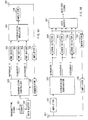
- the transmitting side of the radio communication apparatus shown in FIG. 1A comprises a data buffer 1 for temporarily storing transmitting signals, a modulator 2 for providing BPSK modulation to the transmitting signals, a modulator 3 for providing QPSK modulation to the transmitting signals, a modulator 4 for providing 16QAM modulation to the transmitting signals, an amplifier 5 for amplifying modulated signals, an antenna 6 for radio receiving and transmitting signals, a level detector 7 for detecting the levels of the signals received from the antenna 6, a rate selector 8 for selecting a data transmission rate from the level of each received signal so as to generate rate selective information, which shows a data transmission rate, and switches 9 and 10, which are switch-controlled by the rate selector 8.
- the receiving side of the radio communication apparatus shown in FIG. 1B comprises an antenna 21 for radio receiving and transmitting signals, an amplifier 22 for amplifying the received signals, a demodulator 23 for providing BPSK demodulation to the received signals, a demodulator 24 for providing QPSK demodulation to the received signals, a demodulator 25 for providing 16QAM demodulation to the received signals, a data buffer 26 for storing demodulated signals, a BPSK demodulator 27 for BPSK demodulating the received signals so as to extract rate selective information, a rate detector 28 for detecting a data transmission rate from the output of the BPSK demodulator 27, and switches 29 and 30, which are switch-controlled by the rate detector 28.
- the transmitting side since the propagation path for a reverse link is the same as for a forward link, it is possible for the transmitting side to measure the level of the received signal and to select a modulation system of the transmitting signal based on the level of the received signal.
- the rate selector 8 of the transmitting side determines that the network state is good when the level of the received signal is high, and selects the modulation system of such as 16QAM, etc., in which an error occurs easily but a transmission rate is high, so as to control switches 8 and 10. Also, the rate selector 8 determines that the network state is poor when the level of the received signal is low, and selects the modulation system of such as BPSK, etc., in which a transmission rate is low but an error does not easily occurs, so as to control switches 8 and 10. Furthermore, the rate selector 8 stores rate selective information to the data buffer 1.
- the transmitting signal stored in the data buffer 1 is modulated by the modulation system selected by the rate selector 8. However, the transmitting signal is always modulated by BPSK system in order that errors are not easily generated.
- the modulated signal is amplified by the amplifier 5, thereafter the amplified signal is radio transmitted from the antenna 6.
- the signal received by the antenna 21 of the receiving side is amplified by the amplifier 22, thereafter rate selective information is extracted by BPSK( demodulator 27, and a data transmission rate is detected by the rate detector 28. Then, the switches 29 and 30 are switch-controlled based on the detected data transmission rate, and the received signal is demodulated by the demodulation system having the same data transmission rate as that of the modulation system. A demodulation result is stored in the data buffer 26 and then fetched as a received signal.
- FIG. 2 is a block diagram showing the configuration of the conventional radio communication apparatus of FDD transmission system.
- FIG. 2A shows the configuration of the transmitting side
- FIG. 2B shows the configuration of the receiving side.
- the same reference numerals as those of FIG. 1 are added to the portions common to FIG. 1, and the explanation is omitted.
- the receiving side measures the level of the received signal, and selects a modulation system of the transmitting signal based on the level of the received signal.
- the transmitting side of the radio communication apparatus shown in FIG.2 comprises an amplifier 11 for amplifying received signals, a demodulator 12 for extracting rate selective information from the received signals and a rate detector 13 for detecting a data transmission rate from rate selective information, in place of the level detector 7 and the rate selector 8.
- the receiving side comprises the level detector 31 for detecting for detecting the level of each received signal, a rate selector 32 for selecting a data transmission rate from the level of the received signal so as to generate rate selective information, which shows a data transmission rate, a modulator 33 for modulating rate selective information and an amplifier 34 for amplifying modulated rate selective information, in place of BPSK demodulator 27 and rate selector 28.
- the rate selector 32 of the receiving side determines that the network state is good when the level of the received signal is high, and selects the modulation system such as 16 QAM, etc., in which an error is easily generated but a transmission rate is high, and outputs rate selective information to the modulator 33. Also, the rate selector 32 of the receiving side determines that the network state is poor when the level of the received signal is low, and selects the modulation system such as BPSK, etc., in which a transmission rate is low but an error is not easily generated, and outputs rate selective information to the modulator 33.
- the modulator 33 modulates the rate selective information using the BPSK system in which the error is not easily generated, and a modulated result is amplified by the amplifier 34, and then transmitted to the transmitting side from the antenna 21.
- the rate selector 32 outputs rate selective information, and controls the switches 29 and 30 to make preparations for performing demodulation corresponding to a specified data transmission rate at the same time.
- a demodulation result is stored in the data buffer 26, and then fetched as a received signal.
- the signal received by the antenna 6 of the transmitting side is amplified by the amplifier 11, and then demodulated by the demodulator 12, so that rate selective information is extracted. Then, the rate detector 13 detects a data transmission rate from rate selective information and the switches 9 and 10 are controlled, so that the data transmission rate of the transmitting signal is determined.
- the transmitting signal is temporarily stored in the data buffer 1, and the stored signal is modulated by any one of BPSK modulator 2, QPSK modulator 3, 16QAM modulator 4 in accordance with the control of the rate detector 13, and the modulated signal is amplified by the amplifier 5, and transmitted from the antenna 6 of the transmitting side.
- the conventional radio communication apparatus which adaptively controls the rata transmission rate, improves transmission efficiency using the modulation system with a high transmission rate when the network state is good, and transmits data without fail using the modulation system, in which a data transmission rate is low but an error is not easily generated, when the network state is poor, and this increases an average transmission efficiency of data.
- the above conventional radio communication apparatus must pass rate selective information between the transmitting side and the receiving side, and has a problem in which transmission efficiency drops when rate selective information is in error. Also, there is a problem in which only the reception level is not adequate for determining the network state and accuracy in estimation of receiving quality worsens when multipath fading occurs. Moreover, there is a problem in which the network state at a rate selecting time and the network state at a signal transmitting time change when fading speed is high, and this prevents transmission efficiency from being sufficiently improved.
- An object of the present invention is to provide a transmitting apparatus and a receiving apparatus in which a data transmission rate is automatically changed in accordance with a network state without passing rate selective information, and to provide a data transmitting method.
- the above object can be attached by the configuration in which a transmitting side distributes transmitting signals to a plurality of hierarchies in unit of cell and provides coding processing such that an error detection can be performed for each hierarchy and carries out hierarchical modulation so as to transmit the signals, and a receiving side demodulates received signals for each hierarchy and performs an error detection, and provides a re-transmission request to each hierarchy.
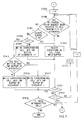
- FIG. 3 is a block diagram showing the configuration of the radio communication apparatus according to Embodiment 1 of the present invention.
- FIG. 3A shows a side that hierarchically modulates data and transmits it (hereinafter referred to as “transmitting side")
- FIG. 3B shows a side that receives hierarchically modulated data (hereinafter referred to as “receiving side”).
- the transmitting side of the radio communication apparatus shown in FIG. 3A comprises a coder 101 for providing coding for an error detection to transmitting signals, a data buffer 102 for temporarily storing the coded transmitting signals, a hierarchical modulator 103 for hierarchically modulating the coded signals, an amplifier 104 for amplifying the hierarchically modulated signals, an antenna 105 for receiving and transmitting signals, an amplifier 106 for amplifying a re-transmission request signal from the receiving side, and a demodulator 107 for demodulating the re-transmission request signal.
- the receiving side shown in FIG. 3B comprises an antenna 151 for receiving and transmitting signals, an amplifier 152 for amplifying received signals, a hierarchical demodulator 153 for hierarchically demodulating the received signals amplified, error detectors 154, 155 for detecting errors of the received signals, a data buffer 157 for temporarily storing the received signals, a modulator 158 for modulating a re-transmission request signal, and an amplifier 159 for amplifying the re-transmission request signal.
- the coder 101 of the transmitting side distributes the transmitting signals to a plurality of hierarchies in unit of cell and performs coding such that an error detection can be carried out for each hierarchy, and stores the result to the data buffer 102.
- the cell distributed to each hierarchy is hierarchically modulated by the hierarchical modulator 103, and the modulation result is amplified by the amplifier 104, and the amplified result is transmitted from the antenna 105.
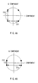
- the hierarchical modulation is a system that makes a difference in the quality between a plurality of signals transmitted on the same network by putting some contrivance of the arrangement of signal points thereby performing modulation.
- FIG. 4A shows the arrangement of signal points of general QPSK modulation.
- the quality of I component is the same as that of Q component.
- FIG. 4B shows the arrangement of signal points of QPSK modulation to which hierarchical modulation is provided.
- the quality of I component is better than that of Q component.
- FIG. 4B shows that the quality of Q component is bad but that of I component is good.
- the signal received by the antenna 151 is amplified by the amplifier 152, and the amplified signal is hierarchically demodulated by the hierarchical demodulator 153 so as to pick up the cells of the respective hierarchies.
- the hierarchically modulated cells are subjected to error detection processing for each hierarchy by the error detectors 154 and 155, and a re-transmission request signal relating to the cell in which an error has been detected is output.
- the re-transmission request signal is modulated by the modulator 158 and the modulated signal is amplified by the amplifier 159, and the amplified signal is transmitted from the antenna 151.
- the re-transmission request signal transmitted from the receiving side is detected by the demodulator 107 via the antenna 105 and amplifier 106, and the detection result is output to the data buffer 102. Then, the cell, which has been requested to be re-transmitted, is automatically read from the data buffer 102 again and re-transmitted.
- Hierarchies 1 and 2 of FIG. 3 are I component and Q component of FIG. 4B, respectively.
- hierarchy 1 with high quality can succeed in data transmission, so that transmission efficiency, which corresponds to BPSK data transmission rate with one bit per one symbol, can be ensured.
- the cell transmitted from hierarchy 2 is re-transmitted repeatedly until hierarchy 2 succeeds in data transmission. In this case, however, if the number of re-transmissions exceeds the buffer size, the corresponding cell is discarded.
- hierarchy 2 with low quality can also succeed in data transmission in addition to hierarchy 1, so that transmission efficiency, which corresponds to QPSK data transmission rate with two bits per one symbol, can be obtained.
- the transmitting side distributes the transmitting signals to the plurality of hierarchies in unit of cell and provides coding processing such that error detection can be performed for each hierarchy so as to carry out hierarchical modulation, and the receiving side performs error detection for each hierarchy, and this makes it possible to adaptively control the data transmission rate automatically in accordance with the network state without passing rate selective information there between.
- Embodiment 1 explains the case in which the number of hierarchies is two, there is no limitation in the number of hierarchies, and any number of hierarchies can be used in the present invention.
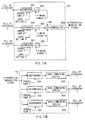
- FIG. 5 is a block diagram showing the configuration of the radio communication apparatus according to Embodiment 2.
- FIG. 5A shows the transmitting side
- FIG. 5B shows the receiving side.
- the same reference numerals as those of FIG. 3 are added to the same configuration elements as those of FIG. 3, and the explanation is omitted.
- FIG. 3 shows the case in which the number of hierarchies is 2 and FIG. 5 shows a case in which the number of hierarchies is 3 just for explanation, this makes no fundamental difference there between.
- the transmission controller 301 controls the hierarchies of the respective cells stored in the data buffer 102, and stores them to the TMP buffers 302, 303, 304. Also, delete processing of cells, which have been written into the data buffer 102 and TMP buffers 302, 303, 304, is performed. Moreover, in a case where the re-transmission request signal is input from the demodulator 107, the corresponding cell is written into the TMP buffer, which is different from the previous one, thereby controlling the re-transmitting cell to be transmitted at the hierarchy, which is different from the previous one.
- i denotes the number of hierarchies. Also, the smaller the value of i is, the better the quality of hierarchy becomes, and hierarchy 1 has the highest quality and hierarchy I has the lowest quality.
- TMP buffers 302, 303, 304 are deleted (ST401).
- transmission cells input from the data buffer 102 are written into vacant TMP buffers 302, 303, 304 (ST402).
- the cells written into the respective TMP buffers are hierarchically modulated by the hierarchical modulator 103, and the amplitude thereof is amplified by the amplifier 104, and the result is radio transmitted from the antenna 105.
- one rank of the hierarchy of re-transmitting cell is moved up as compared with one previously transmitted, and the corresponding cell is written to the TMP buffer (ST408, and ST409).
- the transmission after moving up one rank of the hierarchy of re-transmitting cell makes it possible to transmit the cell automatically during the repetition of re-transmission request at the hierarchy where errors occur least. This makes it possible to reduce the probability of the repetition of re-transmission and a cell discard rate and to increase reliability of transmission.
- the corresponding cell is deleted from the data buffer 102 (ST410).
- FIG. 8 is a schematic view showing the cells, which are written into the TMP buffers of the respective hierarchies of the radio communication apparatus according to Embodiment 2.
- the hierarchies are used in rotation, and the transmission is performed at the hierarchy different from the previous one at the re-transmission time. This makes it possible to automatically transmit the cell at the hierarchy with the highest quality by repeating the re-transmission even if the bad network state is continued for a long period of time, and this allows the probability of re-transmission and the cell discard rate to be reduced.
- Embodiment 2 there is no limitation in the number of hierarchies and a control algorithm. Moreover, in Embodiment 2, though the hierarchy where the cell is written is moved up one by one every re-transmission, it is possible to perform the other control such as the hierarchy where the re-transmitting cell is written is unconditionally moved up to hierarchy 1.
- FIG. 9 is a block diagram showing the partial configuration of the radio communication apparatus according to Embodiment 3 of the present invention.
- FIG. 9A shows the configuration of the hierarchical modulator of the radio communication apparatus
- FIG. 9B shows the configuration of the hierarchical demodulator of the radio communication apparatus.
- the hierarchical modulator 103 shown in FIG. 9A comprises a plurality of spreaders 601, 602, 603 for performing spread processing, an adder 604 for adding spread signals output from the respective spreaders, and a modulator 605 for modulating the added spread signal.
- the hierarchical demodulator 123 shown in FIG. 9B comprises a plurality of despreaders 651, 652, 653 for performing despread processing, and RAKE combining devices 654, 655, 656 for RAKE combining outputs of the respective despreaders.
- the spreader 601 provides spread processing to the cell distributed to hierarchy 1 using a spread code A, and amplifies a spread signal based on a level setting signal A.
- the spreader 602 provides spread processing to the cell distributed to hierarchy 2 using a spread code B, and amplifies a spread signal based on a level setting signal B.
- the spreader 603 provides spread processing to the cell distributed to hierarchy 3 using a spread code C, and amplifies a spread signal based on a level setting signal C.
- each of the level setting signal A, level setting signal B and level setting signal C specifies a different level.
- the spread code A, spread code B, and spread code C have orthogonality mutually.
- the spread signals output from the respective sreaders are added by the adder 604, and the added spread signal is modulated by the modulator 605, and the modulated signal is output from the hierarchical modulator 103 as a hierarchical modulated output.
- the despreader 651 provides despread processing to the input signal using the same spread code A as used in the spread processing of spreader 601 so as to pick up the cell distributed to the hierarchy 1.
- the RAKE combining device 654 RAKE combines the cells output from the despreader 651.
- the despreader 652 provides despread processing to the input signal using the same spread code B as used in the spread processing of spreader 602 so as to pick up the cell distributed to the hierarchy 2.
- the RAKE combining device 655 RAKE combines the cells output from the despreader 652.
- the despreader 653 provides despread processing to the input signal using the same spread code C as used in the spread processing of spreader 603 so as to pick up the cell distributed to the hierarchy 3.
- the RAKE combining device 656 RAKE combines the cells output from the despreader 653.
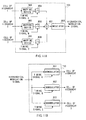
- FIG. 10 is a block diagram showing the partial configuration of the radio communication apparatus according to Embodiment 4 of the present invention.
- FIG. 10A shows the configuration of the hierarchical modulator of the radio communication apparatus
- FIG. 10B shows the configuration of the hierarchical demodulator of the radio communication apparatus.
- the hierarchical modulator 103 shown in FIG. 10A comprises a plurality of modulators 701, 702, 703 each performing modulation using a different sub-carrier, and an adder 704 for adding modulated signals output from the respective modulators.
- the hierarchical demodulator 123 shown in FIG. 10B comprises a plurality of demodulator 751, 752, 753 each performing demodulation processing.
- the modulator 701 provides modulation processing to the cell distributed to the hierarchy 1 using a sub-carrier A, and amplifies the modulated signal based on the level setting signal A.
- the modulator 702 provides modulation processing to the cell distributed to the hierarchy 2 using a sub-carrier B, and amplifies the modulated signal based on the level setting signal B.
- the modulator 703 provides modulation processing to the cell distributed to the hierarchy 3 using a sub-carrier C, and amplifies the modulated signal based on the level setting signal C.
- each of the level setting signal A, level setting signal B and level setting signal C specifies a different level.
- each of the sub-carrier A, sub-carrier B, and sub-carrier C specifies a different level to maintain orthogonality mutually.
- the signals output from the respective modulators are added by the adder 704, and the added signal is output from the hierarchical modulator 103 as a hierarchical modulated output.
- the demodulator 751 provides demodulation processing to the input signal using the same sub-carrier A as used in the modulation processing of modulator 701 so as to pick up the cell distributed to the hierarchy 1.
- the demodulator 752 provides demodulation processing to the input signal using the same sub-carrier B as used in the modulation processing of modulator 702 so as to pick up the cell distributed to the hierarchy 2.
- the demodulator 753 provides demodulation processing to the input signal using the same sub-carrier C as used in the modulation processing of modulator 703 so as to pick up the cell distributed to the hierarchy 3.
- FIG. 11 is a block diagram showing the partial configuration of the radio communication apparatus according to Embodiment 5 of the present invention.
- FIG. 11A shows the configuration of the hierarchical modulator of the radio communication apparatus
- FIG. 11B shows the configuration of the hierarchical demodulator of the radio communication apparatus.
- the hierarchical modulator 103 shown in FIG. 11A comprises a plurality of mapping devices 801, 802, 803 for each performing a different mapping processing, connection switches 804, 805, 806 for adjusting the output timing of each mapping device, an adder 807 for adding the mapped signals, and a modulator 808 for modulating the added signal.
- the hierarchical modulator 123 shown in FIG. 11B comprises a plurality of demodulators 851, 852, 853.
- the mapping device 801 provides mapping to the cell distributed to the hierarchy 1 by use of BPSK modulation.
- the mapping device 802 provides mapping to the cell distributed to the hierarchy 2 by use of QPSK modulation.
- the mapping device 803 provides mapping to the cell distributed to the hierarchy 3 by use of sub-carrier C.
- the outputs of the respective mapping devices are output to the adder 807 at a different time by the control against the connection switches 804, 805, 806 of timing signal A, timing signal B, and timing signal C, and added by the adder 807. Thereafter, the result of addition is modulated by the modulator 808, and the result of modulation is output from the hierarchical modulator 103 as a hierarchical modulated output.
- the signals each having a different mapping are output at the different time, making it possible to transmit the signals each having a different quality depending on time.
- the demodulator 851 provides demodulation processing to the input signal using timing signal A so as to pick up the cell distributed to the hierarchy 1.
- the demodulator 852 provides demodulation processing to the input signal using timing signal B so as to pick up the cell distributed to the hierarchy 2.
- the demodulator 853 provides demodulation processing to the input signal using timing signal C so as to pick up the cell distributed to the hierarchy 3.
- FIG. 12 is a block diagram showing the partial configuration of the radio communication apparatus according to Embodiment 6 of the present invention.
- FIG. 12A shows the configuration of the hierarchical modulator of the radio communication apparatus
- FIG. 12B shows the configuration of the hierarchical demodulator of the radio communication apparatus.
- the hierarchical modulator 103 shown in FIG. 12A comprises a plurality of a plurality of spreaders 901, 902, 903 for performing spread processing, connection switches 904, 905, 906 for adjusting the output timing of the respective spreaders, an adder 907 for adding the respective spread signals, and a modulator 908 for modulating the added spread signal.
- the hierarchical demodulator 123 shown in FIG. 12B comprises a plurality of despreaders 951, 952, 953 for performing despread processing, and RAKE combining devices 954, 955, 956 for RAKE combining outputs of the respective despreaders.
- the spreader 901 provides spread processing to the cell distributed to the cell 1 using the spread code A, and amplifies the spread signal based on the level setting signal A.
- the spreader 902 provides spread processing to the cell distributed to the cell 2 using the spread code B, and amplifies the spread signal based on the level setting signal B.
- the spreader 903 provides spread processing to the cell distributed to the cell 3 using the spread code C, and amplifies the spread signal based on the level setting signal C.
- each of the sperad code A, spread code B, spread C has a different spread rate.
- each of the level setting signal A, level setting signal B and level setting signal C may specify a different level. If all transmission levels are set to be constant, the greater the spread rate is, the better the quality of the signal becomes.
- the spread signals of the respective spreaders are output to the adder at a different time by the control against the connection switches 904, 905, 906 of timing signal A, timing signal B, and timing signal C, and added by the adder 907. Thereafter, the result of addition is modulated by the modulator 908, and the result of modulation is output from the hierarchical modulator 103 as a hierarchical modulated output.
- the signals each having a different spread rate are output at the different time, making it possible to transmit the signals each having a different quality depending on time.
- the despreader 951 provides despread processing to the input signal using the same spread code A as used in the spread processing of spreader 901 so as to pick up the cell distributed to the hierarchy 1.
- the RAKE combining device 954 RAKE combines the cells output from the despreader 951.
- the despreader 952 provides despread processing to the input signal using the same spread code B as used in the spread processing of spreader 902 so as to pick up the cell distributed to the hierarchy 2.
- the RAKE combining device 955 RAKE combines the cells output from the despreader 952.
- the despreader 953 provides despread processing to the input signal using the same spread code C as used in the spread processing of spreader 903 so as to pick up the cell distributed to the hierarchy 3.
- the RAKE combining device 956 RAKE combines the cells output from the despreader 953.
- a transmitting side distributes transmitting signals to a plurality of hierarchies in unit of cell and provides coding processing so that error detection can be performed for each hierarchy and carries out hierarchical modulation so as to transmit the signals
- a receiving side performs demodulation for each hierarchy and carries out an error detection, and provides a re-transmission request to each hierarchy, thereby making it possible to automatically change a data transmission rate in accordance with the network state without passing rate selective information between the apparatuses.
Landscapes
- Engineering & Computer Science (AREA)
- Computer Networks & Wireless Communication (AREA)
- Signal Processing (AREA)
- Quality & Reliability (AREA)
- Multimedia (AREA)
- Mobile Radio Communication Systems (AREA)
- Detection And Prevention Of Errors In Transmission (AREA)
- Data Exchanges In Wide-Area Networks (AREA)
Applications Claiming Priority (3)
| Application Number | Priority Date | Filing Date | Title |
|---|---|---|---|
| JP10192078A JP2000031944A (ja) | 1998-07-07 | 1998-07-07 | 送信装置並びに受信装置及びデータ伝送方法 |
| JP19207898 | 1998-07-07 | ||
| PCT/JP1999/003609 WO2000002359A1 (fr) | 1998-07-07 | 1999-07-05 | Emetteur et recepteur et procede de transmission de donnees |
Publications (1)
| Publication Number | Publication Date |
|---|---|
| EP1011245A1 true EP1011245A1 (en) | 2000-06-21 |
Family
ID=16285280
Family Applications (1)
| Application Number | Title | Priority Date | Filing Date |
|---|---|---|---|
| EP99926926A Withdrawn EP1011245A1 (en) | 1998-07-07 | 1999-07-05 | Transmitter and receiver and data transmission method |
Country Status (7)
| Country | Link |
|---|---|
| EP (1) | EP1011245A1 (zh) |
| JP (1) | JP2000031944A (zh) |
| KR (1) | KR20010023712A (zh) |
| CN (1) | CN1273732A (zh) |
| AU (1) | AU4397299A (zh) |
| CA (1) | CA2301226A1 (zh) |
| WO (1) | WO2000002359A1 (zh) |
Cited By (26)
| Publication number | Priority date | Publication date | Assignee | Title |
|---|---|---|---|---|
| EP1202487A2 (en) * | 2000-10-31 | 2002-05-02 | Kabushiki Kaisha Toshiba | Data transmission apparatus and method |
| WO2002043293A1 (fr) * | 2000-11-27 | 2002-05-30 | Matsushita Electric Industrial Co., Ltd. | Appareil et procede de communication ofdm |
| WO2002073916A1 (en) * | 2001-03-13 | 2002-09-19 | Matsushita Electric Industrial Co. Ltd. | Method and system for blind detection of modulation type |
| EP1396109A1 (en) * | 2001-06-05 | 2004-03-10 | Nortel Networks Limited | Adaptive coding and modulation |
| EP1579601A2 (en) * | 2002-10-25 | 2005-09-28 | The Directv Group, Inc. | Feeder link configurations to support layererd modulation for digital signals |
| US6999497B2 (en) | 2000-03-15 | 2006-02-14 | Matsushita Electric Industrial Co., Ltd. | Data transmitting apparatus and data transmitting method |
| EP1690340A2 (en) * | 2003-11-26 | 2006-08-16 | Delphi Technologies Inc. | Method to minimize compatibility error in hierarchical modulation |
| EP1690343A2 (en) * | 2003-11-26 | 2006-08-16 | Delphi Technologies, Inc. | Method to minimize compatibility error in hierarchical modulation using variable phase |
| US7295538B2 (en) | 2003-02-07 | 2007-11-13 | Matsushita Electric Industrial Co., Ltd | Radio transmission device and transmission rate decision method |
| EP1873948A1 (en) * | 2005-04-18 | 2008-01-02 | Mitsubishi Denki Kabushiki Kaisha | Sending station, receiving station, and radio communication method |
| US7400687B2 (en) | 2002-04-12 | 2008-07-15 | Matsushita Electric Industrial Co., Ltd | Multicarrier communication apparatus and multicarrier communication method |
| US7609687B2 (en) | 2003-12-15 | 2009-10-27 | Panasonic Corporation | Home agent apparatus, mobile router communication system, and communication method |
| US7702025B2 (en) | 2001-08-31 | 2010-04-20 | Panasonic Corporation | Transmission/reception apparatus and transmission/reception method |
| US7706466B2 (en) | 2001-04-27 | 2010-04-27 | The Directv Group, Inc. | Lower complexity layered modulation signal processor |
| US7738587B2 (en) | 2002-07-03 | 2010-06-15 | The Directv Group, Inc. | Method and apparatus for layered modulation |
| US7778365B2 (en) | 2001-04-27 | 2010-08-17 | The Directv Group, Inc. | Satellite TWTA on-line non-linearity measurement |
| US7822154B2 (en) | 2001-04-27 | 2010-10-26 | The Directv Group, Inc. | Signal, interference and noise power measurement |
| WO2010136680A1 (fr) * | 2009-05-29 | 2010-12-02 | Alcatel Lucent | Transmetteur de donnees multi-format |
| US7920643B2 (en) | 2001-04-27 | 2011-04-05 | The Directv Group, Inc. | Maximizing power and spectral efficiencies for layered and conventional modulations |
| US8005035B2 (en) | 2001-04-27 | 2011-08-23 | The Directv Group, Inc. | Online output multiplexer filter measurement |
| US8208526B2 (en) | 2001-04-27 | 2012-06-26 | The Directv Group, Inc. | Equalizers for layered modulated and other signals |
| US8259641B2 (en) | 2001-04-27 | 2012-09-04 | The Directv Group, Inc. | Feeder link configurations to support layered modulation for digital signals |
| US8379769B2 (en) | 2010-03-10 | 2013-02-19 | Delphi Technologies, Inc. | Communication system utilizing a hierarchically modulated signal and method thereof |
| EP2587703A1 (en) | 2011-10-25 | 2013-05-01 | Alcatel-Lucent | A data retransmission request device, a data transmitter, and a data retransmission method for multi-tone systems |
| WO2019192684A1 (en) * | 2018-04-04 | 2019-10-10 | Telefonaktiebolaget Lm Ericsson (Publ) | Technique for radio transmission under varying channel conditions |
| CN110336644A (zh) * | 2019-07-15 | 2019-10-15 | 杭州泽铭睿股权投资有限公司 | 一种高维调制下的分层编码方法 |
Families Citing this family (20)
| Publication number | Priority date | Publication date | Assignee | Title |
|---|---|---|---|---|
| KR100434459B1 (ko) * | 2000-06-27 | 2004-06-05 | 삼성전자주식회사 | 이동통신 시스템에서 패킷의 전송 제어방법 및 장치 |
| DE60117263T2 (de) | 2000-07-03 | 2006-07-27 | Matsushita Electric Industrial Co., Ltd., Kadoma | Basisstationseinheit und verfahren zur funkkommunikation |
| WO2002056631A1 (fr) * | 2001-01-05 | 2002-07-18 | Matsushita Electric Industrial Co., Ltd. | Systeme de communication mobile et procede de transmission radio |
| JP3545726B2 (ja) | 2001-02-27 | 2004-07-21 | 松下電器産業株式会社 | 受信側装置 |
| JP2002290362A (ja) | 2001-03-26 | 2002-10-04 | Ntt Docomo Inc | 適応変調方法、無線制御装置、及び移動通信システム |
| KR20030035449A (ko) * | 2001-10-31 | 2003-05-09 | 엘지전자 주식회사 | 이동통신 시스템의 데이터 전송방법 |
| US6771693B2 (en) * | 2001-12-27 | 2004-08-03 | Interdigital Technology Corporation | Enhanced rake structure |
| CN100514895C (zh) | 2002-03-29 | 2009-07-15 | 松下电器产业株式会社 | 在多载波发送中的数据重发方法 |
| JP3899005B2 (ja) | 2002-10-03 | 2007-03-28 | 株式会社エヌ・ティ・ティ・ドコモ | 変調装置、変調方法、復調装置及び復調方法 |
| WO2006041341A1 (en) * | 2004-10-15 | 2006-04-20 | Telefonaktiebolaget Lm Ericsson (Publ) | Method and system of radio communicationswith various resolution levels of signal modulation depending on propagation conditions |
| CN102307074B (zh) * | 2004-12-14 | 2014-05-07 | 富士通株式会社 | 通信系统 |
| JP2008527927A (ja) * | 2005-01-11 | 2008-07-24 | クゥアルコム・インコーポレイテッド | 階層化された変調システムにおいてデータを復号する方法および装置 |
| DE102005032080A1 (de) * | 2005-07-08 | 2007-01-11 | Siemens Ag | Verfahren zum Senden eines Mediadatenstroms und Verfahren zum Empfangen und Erstellen eines rekonstruierten Mediadatenstroms, sowie dazugehörige Sendevorrichtung und Empfangsvorrichtung |
| CN101110815B (zh) * | 2006-07-17 | 2011-12-07 | 中兴通讯股份有限公司 | 一种无线局域网多速率自适应传输的方法 |
| JP4275167B2 (ja) | 2006-11-24 | 2009-06-10 | 株式会社エヌ・ティ・ティ・ドコモ | 送信機 |
| KR100909280B1 (ko) | 2007-06-20 | 2009-07-27 | 한국전자통신연구원 | 계층 변조 신호 수신 장치 및 방법 |
| CN101340225B (zh) * | 2007-07-03 | 2012-07-04 | 华为技术有限公司 | 一种数据发送方法及发射机、接收机和无线通信系统 |
| JP5135603B2 (ja) * | 2007-08-24 | 2013-02-06 | 国立大学法人横浜国立大学 | マルチレベル符号化変調を用いた再送方法、送信機および受信機 |
| CN101674188B (zh) * | 2008-09-11 | 2013-08-14 | 株式会社Ntt都科摩 | 一种基于hm的mbms发送、接收方法及相应装置 |
| CN102439887B (zh) * | 2011-10-18 | 2015-01-07 | 华为技术有限公司 | 信号调制装置和调制方法 |
Family Cites Families (5)
| Publication number | Priority date | Publication date | Assignee | Title |
|---|---|---|---|---|
| JP3139936B2 (ja) * | 1995-03-24 | 2001-03-05 | 株式会社東芝 | 直交周波数分割多重伝送方式とその送信装置および受信装置 |
| JPH09116903A (ja) * | 1995-10-16 | 1997-05-02 | Nippon Telegr & Teleph Corp <Ntt> | 階層化符号化装置および階層化復号化装置 |
| JP3161506B2 (ja) * | 1996-05-16 | 2001-04-25 | 日本電信電話株式会社 | 階層符号化装置、階層復号化装置および階層符号化・復号化装置 |
| JP3431123B2 (ja) * | 1997-03-05 | 2003-07-28 | 日本電信電話株式会社 | データ伝送方法およびその装置 |
| JP2862527B1 (ja) * | 1997-11-18 | 1999-03-03 | 株式会社ワイ・アール・ピー移動通信基盤技術研究所 | スペクトル拡散通信装置 |
-
1998
- 1998-07-07 JP JP10192078A patent/JP2000031944A/ja active Pending
-
1999
- 1999-07-05 EP EP99926926A patent/EP1011245A1/en not_active Withdrawn
- 1999-07-05 WO PCT/JP1999/003609 patent/WO2000002359A1/ja not_active Application Discontinuation
- 1999-07-05 CN CN99801098A patent/CN1273732A/zh active Pending
- 1999-07-05 AU AU43972/99A patent/AU4397299A/en not_active Abandoned
- 1999-07-05 CA CA002301226A patent/CA2301226A1/en not_active Abandoned
- 1999-07-05 KR KR1020007002366A patent/KR20010023712A/ko not_active Application Discontinuation
Non-Patent Citations (1)
| Title |
|---|
| See references of WO0002359A1 * |
Cited By (53)
| Publication number | Priority date | Publication date | Assignee | Title |
|---|---|---|---|---|
| US6999497B2 (en) | 2000-03-15 | 2006-02-14 | Matsushita Electric Industrial Co., Ltd. | Data transmitting apparatus and data transmitting method |
| EP1202487A2 (en) * | 2000-10-31 | 2002-05-02 | Kabushiki Kaisha Toshiba | Data transmission apparatus and method |
| US7437628B2 (en) | 2000-10-31 | 2008-10-14 | Kabushiki Kaisha Toshiba | Data transmission apparatus and method |
| US7193973B2 (en) | 2000-10-31 | 2007-03-20 | Kabushiki Kaisha Toshiba | Data transmission apparatus and method |
| US7502975B2 (en) | 2000-10-31 | 2009-03-10 | Kabushiki Kaisha Toshiba | Data transmission apparatus and method |
| US6993689B2 (en) | 2000-10-31 | 2006-01-31 | Kabushiki Kaisha Toshiba | Data transmission apparatus and method |
| EP1202487B1 (en) * | 2000-10-31 | 2006-04-05 | Kabushiki Kaisha Toshiba | Data transmission apparatus and method |
| US7500159B2 (en) | 2000-10-31 | 2009-03-03 | Kabushiki Kaisha Toshiba | Data transmission apparatus and method |
| US7287201B2 (en) | 2000-10-31 | 2007-10-23 | Kabushiki Kaisha Toshiba | Data transmission apparatus and method |
| US7496807B2 (en) | 2000-10-31 | 2009-02-24 | Kabushiki Kaisha Toshiba | Data transmission apparatus and method |
| WO2002043293A1 (fr) * | 2000-11-27 | 2002-05-30 | Matsushita Electric Industrial Co., Ltd. | Appareil et procede de communication ofdm |
| US7046975B2 (en) | 2001-03-13 | 2006-05-16 | Matsushita Electric Industrial Co., Ltd. | Method and system for blind detection of modulation type |
| WO2002073916A1 (en) * | 2001-03-13 | 2002-09-19 | Matsushita Electric Industrial Co. Ltd. | Method and system for blind detection of modulation type |
| US7706466B2 (en) | 2001-04-27 | 2010-04-27 | The Directv Group, Inc. | Lower complexity layered modulation signal processor |
| US7920643B2 (en) | 2001-04-27 | 2011-04-05 | The Directv Group, Inc. | Maximizing power and spectral efficiencies for layered and conventional modulations |
| US7822154B2 (en) | 2001-04-27 | 2010-10-26 | The Directv Group, Inc. | Signal, interference and noise power measurement |
| US7778365B2 (en) | 2001-04-27 | 2010-08-17 | The Directv Group, Inc. | Satellite TWTA on-line non-linearity measurement |
| US8005035B2 (en) | 2001-04-27 | 2011-08-23 | The Directv Group, Inc. | Online output multiplexer filter measurement |
| US8208526B2 (en) | 2001-04-27 | 2012-06-26 | The Directv Group, Inc. | Equalizers for layered modulated and other signals |
| US8259641B2 (en) | 2001-04-27 | 2012-09-04 | The Directv Group, Inc. | Feeder link configurations to support layered modulation for digital signals |
| EP1396109A1 (en) * | 2001-06-05 | 2004-03-10 | Nortel Networks Limited | Adaptive coding and modulation |
| US7702025B2 (en) | 2001-08-31 | 2010-04-20 | Panasonic Corporation | Transmission/reception apparatus and transmission/reception method |
| US7400687B2 (en) | 2002-04-12 | 2008-07-15 | Matsushita Electric Industrial Co., Ltd | Multicarrier communication apparatus and multicarrier communication method |
| US7738587B2 (en) | 2002-07-03 | 2010-06-15 | The Directv Group, Inc. | Method and apparatus for layered modulation |
| EP1579601A4 (en) * | 2002-10-25 | 2007-06-06 | Directv Group Inc | CONFIGURATIONS OF CONNECTION LINKS FOR SUPPORTING MODULATION IN DIGITAL SIGNAL LAYERS |
| EP1579601A2 (en) * | 2002-10-25 | 2005-09-28 | The Directv Group, Inc. | Feeder link configurations to support layererd modulation for digital signals |
| US7295538B2 (en) | 2003-02-07 | 2007-11-13 | Matsushita Electric Industrial Co., Ltd | Radio transmission device and transmission rate decision method |
| EP1690340A2 (en) * | 2003-11-26 | 2006-08-16 | Delphi Technologies Inc. | Method to minimize compatibility error in hierarchical modulation |
| EP1690340A4 (en) * | 2003-11-26 | 2008-07-02 | Delphi Tech Inc | METHOD FOR MINIMIZING COMPATIBILITY ERRORS IN HIERARCHICAL MODULATION |
| US7751497B2 (en) | 2003-11-26 | 2010-07-06 | Delphi Technologies, Inc. | Method to minimize compatibility error in hierarchical modulation using variable phase |
| US7657225B2 (en) | 2003-11-26 | 2010-02-02 | Delphi Technologies, Inc. | Method to minimize compatibility error in hierarchical modulation using variable phase |
| EP1690343A4 (en) * | 2003-11-26 | 2007-10-31 | Delphi Tech Inc | METHOD FOR MINIMIZING COMPATIBILITY ERRORS IN HIERARCHICAL MODULATION USING A VARIABLE PHASE |
| EP1690343A2 (en) * | 2003-11-26 | 2006-08-16 | Delphi Technologies, Inc. | Method to minimize compatibility error in hierarchical modulation using variable phase |
| US7609687B2 (en) | 2003-12-15 | 2009-10-27 | Panasonic Corporation | Home agent apparatus, mobile router communication system, and communication method |
| EP1873948A1 (en) * | 2005-04-18 | 2008-01-02 | Mitsubishi Denki Kabushiki Kaisha | Sending station, receiving station, and radio communication method |
| EP1873948A4 (en) * | 2005-04-18 | 2011-03-16 | Mitsubishi Electric Corp | TRANSMIT STATION, RECEPTION STATION AND RADIO COMMUNICATION METHOD |
| US8175110B2 (en) | 2005-04-18 | 2012-05-08 | Mitsubishi Electric Corporation | Sending station, receiving station, and radio communication method |
| JP2012528507A (ja) * | 2009-05-29 | 2012-11-12 | アルカテル−ルーセント | 複数フォーマットデータ用送信器 |
| WO2010136680A1 (fr) * | 2009-05-29 | 2010-12-02 | Alcatel Lucent | Transmetteur de donnees multi-format |
| FR2946206A1 (fr) * | 2009-05-29 | 2010-12-03 | Alcatel Lucent | Transmetteur de donnees multi-format |
| US8867652B2 (en) | 2009-05-29 | 2014-10-21 | Alcatel Lucent | Transmitter for multi-format data |
| US8599971B2 (en) | 2010-03-10 | 2013-12-03 | Delphi Technologies, Inc. | Communication system utilizing a hierarchically modulated signal and method thereof |
| US8379769B2 (en) | 2010-03-10 | 2013-02-19 | Delphi Technologies, Inc. | Communication system utilizing a hierarchically modulated signal and method thereof |
| EP2587703A1 (en) | 2011-10-25 | 2013-05-01 | Alcatel-Lucent | A data retransmission request device, a data transmitter, and a data retransmission method for multi-tone systems |
| WO2013060600A1 (en) | 2011-10-25 | 2013-05-02 | Alcatel Lucent | A data retransmission request device, a data transmitter, and a data retransmission method for multi-tone systems |
| CN103891192A (zh) * | 2011-10-25 | 2014-06-25 | 阿尔卡特朗讯 | 用于多频调系统的数据重传请求装置、数据发射器以及数据重传方法 |
| EP2587702A1 (en) * | 2011-10-25 | 2013-05-01 | Alcatel Lucent | A data retransmission request device, a data transmitter, and a data retransmission method for multi-tone systems |
| JP2014531174A (ja) * | 2011-10-25 | 2014-11-20 | アルカテル−ルーセント | マルチトーンシステムのためのデータ再送要求装置、データ送信機、およびデータ再送方法 |
| US9166850B2 (en) | 2011-10-25 | 2015-10-20 | Alcatel Lucent | Data retransmission request device, a data transmitter, and a data retransmission method for multi-tone systems |
| WO2019192684A1 (en) * | 2018-04-04 | 2019-10-10 | Telefonaktiebolaget Lm Ericsson (Publ) | Technique for radio transmission under varying channel conditions |
| US10924207B2 (en) | 2018-04-04 | 2021-02-16 | Telefonaktiebolaget Lm Ericsson (Publ) | Technique for radio transmission under varying channel conditions |
| US11374684B2 (en) | 2018-04-04 | 2022-06-28 | Telefonaktiebolaget Lm Ericsson (Publ) | Technique for radio transmission under varying channel conditions |
| CN110336644A (zh) * | 2019-07-15 | 2019-10-15 | 杭州泽铭睿股权投资有限公司 | 一种高维调制下的分层编码方法 |
Also Published As
| Publication number | Publication date |
|---|---|
| CA2301226A1 (en) | 2000-01-13 |
| WO2000002359A1 (fr) | 2000-01-13 |
| AU4397299A (en) | 2000-01-24 |
| JP2000031944A (ja) | 2000-01-28 |
| CN1273732A (zh) | 2000-11-15 |
| KR20010023712A (ko) | 2001-03-26 |
Similar Documents
| Publication | Publication Date | Title |
|---|---|---|
| EP1011245A1 (en) | Transmitter and receiver and data transmission method | |
| US10498571B2 (en) | Transmission apparatus, reception apparatus and digital radio communication method | |
| US7515649B2 (en) | Signal transmitting method in mobile communication system | |
| US7486634B2 (en) | Adaptive modulation based on signal quality | |
| US7043210B2 (en) | Adaptive coding and modulation | |
| EP1278327B1 (en) | Packet transmission system and packet transmission method | |
| KR101023330B1 (ko) | 무선 통신 시스템에서 서비스 품질을 보장하기 위한 복합자동 재전송 요구 방법 | |
| US8391403B2 (en) | Method for transmitting signals in a digital communication system and transmitter for a digital communication system | |
| US7277492B2 (en) | Transmission apparatus, transmission control method, reception apparatus, and reception control method | |
| JP3563357B2 (ja) | 適応変調通信システム | |
| JP4623992B2 (ja) | 送信装置ならびに受信装置 | |
| KR100388400B1 (ko) | 송신 장치, 수신 장치, 기지국 장치 및 송신 방법 | |
| US7092434B2 (en) | Mobile station used as a repeater station when communicating with a base station | |
| JP3679759B2 (ja) | 無線送信装置 | |
| US20030072266A1 (en) | Data transmission system and data transmission method | |
| JP4291659B2 (ja) | 送信装置及び送信方法 | |
| US20040177306A1 (en) | Transmission device and transmission method | |
| EP1408640B1 (en) | Diversity combining for phase modulated signals |
Legal Events
| Date | Code | Title | Description |
|---|---|---|---|
| PUAI | Public reference made under article 153(3) epc to a published international application that has entered the european phase |
Free format text: ORIGINAL CODE: 0009012 |
|
| 17P | Request for examination filed |
Effective date: 20000330 |
|
| AK | Designated contracting states |
Kind code of ref document: A1 Designated state(s): AT BE CH CY DE DK ES FI FR GB GR IE IT LI LU MC NL PT SE |
|
| STAA | Information on the status of an ep patent application or granted ep patent |
Free format text: STATUS: THE APPLICATION HAS BEEN WITHDRAWN |
|
| 18W | Application withdrawn |
Withdrawal date: 20020422 |