EP1010984A2 - Verfahren und Vorrichtung zur Erfassung der Beschleunigung - Google Patents
Verfahren und Vorrichtung zur Erfassung der Beschleunigung Download PDFInfo
- Publication number
- EP1010984A2 EP1010984A2 EP99119809A EP99119809A EP1010984A2 EP 1010984 A2 EP1010984 A2 EP 1010984A2 EP 99119809 A EP99119809 A EP 99119809A EP 99119809 A EP99119809 A EP 99119809A EP 1010984 A2 EP1010984 A2 EP 1010984A2
- Authority
- EP
- European Patent Office
- Prior art keywords
- count
- tooth
- acceleration
- tooth count
- teeth
- Prior art date
- Legal status (The legal status is an assumption and is not a legal conclusion. Google has not performed a legal analysis and makes no representation as to the accuracy of the status listed.)
- Withdrawn
Links
Images


Classifications
-
- G—PHYSICS
- G01—MEASURING; TESTING
- G01P—MEASURING LINEAR OR ANGULAR SPEED, ACCELERATION, DECELERATION, OR SHOCK; INDICATING PRESENCE, ABSENCE, OR DIRECTION, OF MOVEMENT
- G01P3/00—Measuring linear or angular speed; Measuring differences of linear or angular speeds
- G01P3/42—Devices characterised by the use of electric or magnetic means
- G01P3/44—Devices characterised by the use of electric or magnetic means for measuring angular speed
- G01P3/48—Devices characterised by the use of electric or magnetic means for measuring angular speed by measuring frequency of generated current or voltage
- G01P3/481—Devices characterised by the use of electric or magnetic means for measuring angular speed by measuring frequency of generated current or voltage of pulse signals
- G01P3/489—Digital circuits therefor
-
- G—PHYSICS
- G01—MEASURING; TESTING
- G01P—MEASURING LINEAR OR ANGULAR SPEED, ACCELERATION, DECELERATION, OR SHOCK; INDICATING PRESENCE, ABSENCE, OR DIRECTION, OF MOVEMENT
- G01P15/00—Measuring acceleration; Measuring deceleration; Measuring shock, i.e. sudden change of acceleration
- G01P15/16—Measuring acceleration; Measuring deceleration; Measuring shock, i.e. sudden change of acceleration by evaluating the time-derivative of a measured speed signal
- G01P15/165—Measuring acceleration; Measuring deceleration; Measuring shock, i.e. sudden change of acceleration by evaluating the time-derivative of a measured speed signal for measuring angular accelerations
Definitions
- This invention relates to an apparatus for and a method of determining the acceleration of a rotating body and more particularly to an apparatus and method of determining the acceleration of a rotating body in a power transmission.
- Multi-speed power transmissions provide automatic ratio interchanges to accomplish efficient use of an internal combustion engine.
- the internal combustion engine has an operating speed range and torque range which limit its direct use in many vehicles.
- the multi-speed transmission extend the usefulness of the engine by reusing a portion to the engine output.
- the transmission provides many speed ratios such that high torque and low speed output range is available at vehicle launch and high speed lower torque output range is available for highway performance.
- the overall efficiency of the vehicle is improved by the proper interchange of transmission ratios while the vehicle speed is increased from launch to cruising.
- Engine throttle position, vehicle speed, engine speed and vehicle acceleration are some of the signals that are utilized. Of these signals, only vehicle acceleration is calculated from other available signals.
- the common method of determining acceleration is to measure the time it takes for a predetermined number of teeth on a rotating gear to pass and calculate the speed. Then, repeat the measurement for a new set of predetermined number of teeth and calculate a new speed. If the measured speeds differ, the component is accelerating and the value is calculated from the successive speeds.
- a method of calculating acceleration form a gear through a magnetic pickup and electronic hardware is provided.
- the acceleration is calculated in software subroutines with the data collected from the magnetic pickup and supplied through the electronic hardware.
- tooth to tooth variations in the gear are eliminated.
- eccentricity effects of the gear are eliminated.
- the number of teeth to be counted to achieve total tooth counts equal to one or more revolutions is adjusted during operation.
- time measurement lag is minimized by calculating the acceleration on each control loop that a new revolution count becomes available.
- a new tooth count based on a tooth count estimate for the next update is determined.
- the number of revolutions to count is increased at higher speeds.
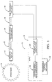
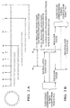
- FIG. 1 there is seen a diagrammatic representation of a control system 10 which measures rotational speed and processes the data to provide the desired control data.
- the rotational speed is sensed by a magnetic pickup 12 operating in conjunction with a toothed gear14.
- the magnetic pickup 12 is a conventional device which works off of the principle that the change in the net amount of flux generated by a changing magnetic field will generate an alternating current signal in the pickup coil.
- This alternating signal 16 is then converted into a square wave 18 using a signal conditioning circuit 20.
- TPU Time Processing Unit 22
- the generated square wave 18 is converted to counts by counting the falling or rising edges of square wave. Each count is the representative of each tooth passed.
- a Central Processing Unit (CPU) 24 commands the TPU 22 how many teeth it would like to be counted.
- the TPU 22 in return generates a hardware interrupt when it has completed the specified tooth count.
- this interrupt occurs, the value of a conventional continuous timer, not shown, is read into a conventional register. This is done to insure that an accurate time is preserved for the calculation of speed based on number of teeth counted.
- the continuous timer mentioned above is an internal time whose value increments by one upon each clock cycle. For a 16 bit system, it continues to increment up to a maximum double byte value of 65535, after which it resets to zero. This resetting to zero is called a timer overflow and also causes an interrupt within the CPU 24 to signal its occurrence. Assuming the CPU 24 clock frequency of 2 MHz, this timer has a period of 32.768 ms.
- the first task of the CPU 24 is to subtract the current timer value latched in a register by interrupt from the timer value which corresponds to the previous interrupt which was stored in memory. This will result in the time interval, in CPU clock cycles, that it took to count the commanded number of teeth.
- the next function of the CPU 24 is to determine if it should command a change in the number of teeth that TPU is counting. It does this by using the time interval. It compares this interval to a window of 22000 to 45000 clock cycles, which corresponds to 11 to 22.5 ms. If the interval falls within this desired window, then the commanded number of teeth to count (1,2,4,8,16,etc) does not usually change unless it is determined that different number of teeth count is required to achieve revolution counts. If, however, the interval is greater than 45000, then the CPU 24 commands to halve the number of teeth it is to count (limited to a minimum of one). Similarly, if the interval is less than 22000, then CPU 24 commands to double the number of teeth to count. The purpose of this adjustment in the number of teeth being counted is to keep the interrupts within a reasonable interval-- fast enough so that CPU 24 has some recent data for better speed processing, and slow enough that the CPU 24 is not overburdened by interrupts.
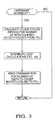
- an interrupt loop calculation 26 is triggered after the TPU 22 has completed an specified tooth count and generated a speed processing interrupt.
- the interrupt loop calculation is a set of software subroutines, including those described in Figures 3 and 4Athat calculate the number of teeth to count next time.
- another interrupt structure triggers a minor loop 28 every 16.384 ms.
- the minor loop 28 is a set of software subroutines, including those described in Figure 5, that calculate the speed and calculation signals, apply the filters for these signals, perform shift scheduling, clutch control, and diagnostics, send pressure commands to the solenoids, and many other functions of a conventional transmission control mechanism 30.
- Speed processing interrupts and the minor loop 28 interrupt structure have no timing relationship and operate asynchronously. Therefore, it is possible to get zero, one, or two speed interrupts through a minor loop 28.
- New_Clock_Cycles may or may not be equal to Old_Clock_Cylces.
- nticks and ntooth_count are the variables name used to describe clock cycles and counted number of teeth respectively. Referring to Figure 3, when nticks and ntooth_count are obtained, a set of computations are made ( Figure 4) to determine the number of teeth to count next time.
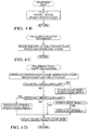
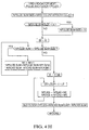
- Figure 4A shows the top level diagram for computations made in the interrupt loop.
- the new data are stored in a set of array ( Figure 4B).
- the cumulative data based on the new information are computed ( Figure 4C).
- a preliminary number of teeth to count for the next time are computed using the current speed processing method ( Figure 4D).
- Figure 4E The number of teeth to be counted are then adjusted to assure the cumulative data in future updates equal one or more gear revolutions ( Figure 4E). At this point, if the number of teeth stored is less than one or more gear revolutions, the number of teeth to count is commanded to the TPU 22.
- Speed processing interrupts and the minor loop interrupt have no timing relationship and operate asynchronously. Therefore, it is possible to get multiples set of cyclical information per minor loop. During a minor loop, if there is any cyclical information available, then a new speed and acceleration are calculated as shown in Figure 5.
- a preliminary tooth count is calculated in Figure 4D. Since it is possible to have a different number of teeth counted (ntooth_count) from the preliminary tooth count calculation (ntooth_count_base) due to further adjustment, an adjusted clock cycle is calculated (nticks_adj). Nticks_adj provides the number of clock cycles as if ntooth_count_base was the number of teeth to count.
- Nticks_adj is used to command a change in the number of teeth to count. It compares this interval to a window of clock cycles (nticks_lower_limit to nticks_upper_limit). If the interval falls within this desired window, then the commanded number of teeth to count does not change. If, however, the interval is greater than nticks_upper_limit, then the CPU 24 commands to half the number of teeth it is to count. Similarly, if the interval is less than nticks_lower_limit, then CPU 24 commands to double the number of teeth to count.
- This adjustment in the number of teeth being counted is to keep the interrupts within a reasonable interval-- fast enough so that CPU 24 has some recent data for better speed processing and slow enough that the CPU 24 is not overburdened by interrupts. It should be noted that the method mentioned here is one of several different methods that can be used to adjust the number of teeth to be counted. This method can be replaced with any other similar method as long as the system constraints (minimum interrupts and most recent data) are met.
- An initial tooth count adjustment is provided by the sub-routine of Figure 4E.
- the tooth count adjustment is made when the term "npulse_sum + 2 * ntooth_count_base” is greater than one or more revolutions.
- the term “2 * ntooth_count_base” represent the maximum possible tooth count for the next update according to the method employed in preliminary tooth count adjustment.
- the sub-routine in Figure 4G will determine the number of revolutions to count.
- the preliminary tooth count (ntooth_count_base) is set higher (i.e., 1,2,4,8,16,32,64,).
- ntooth_count_base is eventually set above the number of teeth per gear(nteeth) through the preliminary tooth count calculation.
- Fixed point math is used to calculate the number of revolutions (nrev_count) in integer (1,2,3,etc.).
- a control loop calculation is made based on one, or two set of cyclical results (nrev) per minor loop as shown in Figure 5.
- the new speed is calculated similar to prior uses with the exception of using the clock cycle and tooth counts based on revolutions rather than interrupts.
- the new acceleration is calculated based on average of old and new clock cycles as shown in Figure 2 and described above. K1 and K2 are calibration constants for this calculation.
- the CPU is informed of the acceleration so that proper control signals can be issued to a transmission control mechanism Name Description Type Range Nteeth Number of teeth per speed gear const. 1-255 ntooth_count Number of teeth to count before issuing an interrupt var. 1-255 It counter for storing the information per interrupt var.
- ntck(i) An array to store ticks (number of clock cycles per interrupt) npls(i) An array to store pulses (number of teeth counted per interrupt) nticks_sum Clock cycles summation var. 1-2**24 npulse_sum Tooth Pulse summation var. 1-255 nrev_count Number of tooth to count to match gear revolution(s) var. 1-255 nticks_rev(i) An array to store clock cycles per revolution (s) npulse_rev(i) An array to store tooth pulses per revolution(s) new_clock_cycles Number of new clock cycles since last revolution count var.
- 1-2**24 nticks_sum_last clock cycles summation, last update var. 1-2**24 nticks_avg(i) An array to store average of new and old clock cycles old_clock_cycles Number of clock cycles that are discarded from last revolution count var. 1-2**24 nticks-adj adjusted number of clock cycles as if number of tooth counted last time were ntooth_count_base var. 1-2**24 ntooth_count_last Previous number of tooth counted var. 1-255 ntooth_count_base Preliminary number of tooth to count next time (before adjustment) var.
Landscapes
- Physics & Mathematics (AREA)
- General Physics & Mathematics (AREA)
- Control Of Transmission Device (AREA)
Applications Claiming Priority (2)
| Application Number | Priority Date | Filing Date | Title |
|---|---|---|---|
| US215938 | 1998-12-18 | ||
| US09/215,938 US6130928A (en) | 1998-12-18 | 1998-12-18 | Acceleration processing method and apparatus |
Publications (2)
| Publication Number | Publication Date |
|---|---|
| EP1010984A2 true EP1010984A2 (de) | 2000-06-21 |
| EP1010984A3 EP1010984A3 (de) | 2002-12-18 |
Family
ID=22805014
Family Applications (1)
| Application Number | Title | Priority Date | Filing Date |
|---|---|---|---|
| EP99119809A Withdrawn EP1010984A3 (de) | 1998-12-18 | 1999-10-06 | Verfahren und Vorrichtung zur Erfassung der Beschleunigung |
Country Status (2)
| Country | Link |
|---|---|
| US (1) | US6130928A (de) |
| EP (1) | EP1010984A3 (de) |
Cited By (4)
| Publication number | Priority date | Publication date | Assignee | Title |
|---|---|---|---|---|
| WO2009087504A1 (en) * | 2008-01-04 | 2009-07-16 | Nxp B.V. | Sensor device |
| WO2009087503A1 (en) * | 2008-01-04 | 2009-07-16 | Nxp B.V. | Sensor device |
| WO2009087502A1 (en) * | 2008-01-04 | 2009-07-16 | Nxp B.V. | Sensor device |
| CN109900922A (zh) * | 2019-03-20 | 2019-06-18 | 西安联飞智能装备研究院有限责任公司 | 转速确定方法、装置、电子设备及可读存储介质 |
Families Citing this family (15)
| Publication number | Priority date | Publication date | Assignee | Title |
|---|---|---|---|---|
| US6691015B1 (en) * | 2000-08-02 | 2004-02-10 | Alfred B. Levine | Vehicle drive overdrive system |
| US6721644B2 (en) * | 2000-08-02 | 2004-04-13 | Alfred B. Levine | Vehicle drive override subsystem |
| US6507799B2 (en) * | 2001-02-26 | 2003-01-14 | Honeywell International Inc. | Method and apparatus for reducing microprocessor speed requirements in data acquisition applications |
| US6532422B1 (en) | 2001-06-29 | 2003-03-11 | Honeywell International, Inc. | Simultaneous injection method and system for a self-balancing rotatable apparatus |
| US6665625B2 (en) | 2001-09-10 | 2003-12-16 | Honeywell International Inc | Energy-based thresholds applied dynamic balancing |
| US6622105B2 (en) | 2001-09-10 | 2003-09-16 | Honeywell International Inc. | Dynamic correlation extension for a self-balancing rotatable apparatus |
| US6701561B2 (en) | 2001-09-10 | 2004-03-09 | Honeywell International Inc. | Method and system for detecting fluid injection from stationary to rotating members |
| US6662682B2 (en) | 2001-11-15 | 2003-12-16 | Honeywell International Inc. | Dynamic balancing application mass placement |
| US6687572B2 (en) | 2001-11-15 | 2004-02-03 | Honeywell International Inc. | Supervisory method and system for improved control model updates applied to dynamic balancing |
| US6681430B2 (en) | 2001-11-15 | 2004-01-27 | Honeywell International Inc. | Method and system for mechanizing simultaneous multi-actuator actions applied to dynamic balancing |
| US6775870B2 (en) | 2001-11-15 | 2004-08-17 | Honeywell International Inc. | Data manipulation method and system for a self-balancing rotatable apparatus |
| US6546354B1 (en) | 2001-11-15 | 2003-04-08 | Honeywell International, Inc. | Resonance identification extension for a self-balancing rotatable apparatus |
| US6647790B2 (en) | 2001-11-15 | 2003-11-18 | Honeywell International Inc. | Fixed-bandwidth correlation window method and system for a self-balancing rotatable apparatus |
| US6795792B2 (en) | 2001-11-15 | 2004-09-21 | Honeywell International Inc. | Continuous flow method and system for placement of balancing fluid on a rotating device requiring dynamic balancing |
| DE102017221876A1 (de) | 2017-12-05 | 2019-06-06 | Zf Friedrichshafen Ag | Gradientenbestimmung |
Family Cites Families (7)
| Publication number | Priority date | Publication date | Assignee | Title |
|---|---|---|---|---|
| JPS56100363A (en) * | 1980-01-14 | 1981-08-12 | Nissan Motor Co Ltd | Detecting apparatus of adjusting speed |
| JPS5759171A (en) * | 1980-09-27 | 1982-04-09 | Toyota Motor Corp | Detection of rotating speed of rotating member in vehicle |
| US4722094A (en) * | 1985-12-16 | 1988-01-26 | Allied Corporation | Digital rate detection circuit |
| CH680963A5 (de) * | 1989-09-01 | 1992-12-15 | Asulab Sa | |
| WO1993020427A1 (en) * | 1992-03-30 | 1993-10-14 | Purdue Research Foundation | Error correction in measures of speed, acceleration, misfire detection and roughness |
| DE19536840A1 (de) * | 1995-10-02 | 1997-04-03 | Asea Brown Boveri | Verfahren zur Drehzahlmessung |
| US5740083A (en) * | 1996-04-01 | 1998-04-14 | Ford Motor Company | Delta time measurement circuit for determining parameter derivatives of a rotational velocity sensor signal |
-
1998
- 1998-12-18 US US09/215,938 patent/US6130928A/en not_active Expired - Lifetime
-
1999
- 1999-10-06 EP EP99119809A patent/EP1010984A3/de not_active Withdrawn
Cited By (5)
| Publication number | Priority date | Publication date | Assignee | Title |
|---|---|---|---|---|
| WO2009087504A1 (en) * | 2008-01-04 | 2009-07-16 | Nxp B.V. | Sensor device |
| WO2009087503A1 (en) * | 2008-01-04 | 2009-07-16 | Nxp B.V. | Sensor device |
| WO2009087502A1 (en) * | 2008-01-04 | 2009-07-16 | Nxp B.V. | Sensor device |
| CN109900922A (zh) * | 2019-03-20 | 2019-06-18 | 西安联飞智能装备研究院有限责任公司 | 转速确定方法、装置、电子设备及可读存储介质 |
| CN109900922B (zh) * | 2019-03-20 | 2021-04-16 | 西安联飞智能装备研究院有限责任公司 | 转速确定方法、装置、电子设备及可读存储介质 |
Also Published As
| Publication number | Publication date |
|---|---|
| US6130928A (en) | 2000-10-10 |
| EP1010984A3 (de) | 2002-12-18 |
Similar Documents
| Publication | Publication Date | Title |
|---|---|---|
| US6130928A (en) | Acceleration processing method and apparatus | |
| US5740083A (en) | Delta time measurement circuit for determining parameter derivatives of a rotational velocity sensor signal | |
| EP0058282B1 (de) | Motordrehzahlmesssystem | |
| US4485452A (en) | Speed measurement system | |
| EP0323696B2 (de) | Verfahren und Vorrichtung zur Überwachung des Betriebes von drehenden Maschinen mittels mitlaufend erzeugter und wiederabgetasteter Funktionen | |
| US4814704A (en) | Rotor position indicator with correction for apparant acceleration and deceleration | |
| JP2539940B2 (ja) | 高効率回転速度計算法 | |
| US4417469A (en) | Speed and timing angle measurement | |
| US4635201A (en) | Apparatus for detecting amount of change in rotational speed of internal combustion engine | |
| US7076361B2 (en) | Engine crankshaft position recognition and tracking method applicable to cam and crankshaft signals with arbitrary patterns | |
| EP0102165A1 (de) | Vorrichtung und Verfahren zum Bestimmen der Geschwindigkeit | |
| EP0059585B1 (de) | Winkelstellungs- und Geschwindigkeitsmessung von Wellen | |
| US4748565A (en) | Apparatus for detecting speed of vehicle with internal combustion engine | |
| US5138640A (en) | Circuit configuration for improving the resolution of successive pulsed signals over time | |
| EP1287366B1 (de) | Geschwindigkeitsmessverfahren und geschwindigkeitsdetektor | |
| US4924420A (en) | Tacho signal processing | |
| US6701275B1 (en) | RPM calculating apparatus for controlling engine, capable of expanding high rpm region without changing calculation period | |
| US4707791A (en) | On-board motor vehicle timing measurement system | |
| NO853419L (no) | Regulator for forbrenningsmotor. | |
| US4745554A (en) | Method of detecting the number of revolutions of internal combustion engine | |
| RU2082088C1 (ru) | Способ измерения углового положения вала | |
| JPS63262570A (ja) | パルス周期計測方式 | |
| SU1021802A1 (ru) | Устройство дл регулировани начала повторных операций | |
| JP2720608B2 (ja) | 計器の指示角度変換方法 | |
| SU1758868A1 (ru) | Преобразователь временных интервалов в код дл измерени угла поворота вала |
Legal Events
| Date | Code | Title | Description |
|---|---|---|---|
| PUAI | Public reference made under article 153(3) epc to a published international application that has entered the european phase |
Free format text: ORIGINAL CODE: 0009012 |
|
| AK | Designated contracting states |
Kind code of ref document: A2 Designated state(s): AT BE CH CY DE DK ES FI FR GB GR IE IT LI LU MC NL PT SE |
|
| AX | Request for extension of the european patent |
Free format text: AL;LT;LV;MK;RO;SI |
|
| PUAL | Search report despatched |
Free format text: ORIGINAL CODE: 0009013 |
|
| AK | Designated contracting states |
Kind code of ref document: A3 Designated state(s): AT BE CH CY DE DK ES FI FR GB GR IE IT LI LU MC NL PT SE |
|
| AX | Request for extension of the european patent |
Free format text: AL;LT;LV;MK;RO;SI |
|
| 17P | Request for examination filed |
Effective date: 20030312 |
|
| AKX | Designation fees paid |
Designated state(s): DE FR GB IT |
|
| GRAP | Despatch of communication of intention to grant a patent |
Free format text: ORIGINAL CODE: EPIDOSNIGR1 |
|
| STAA | Information on the status of an ep patent application or granted ep patent |
Free format text: STATUS: THE APPLICATION IS DEEMED TO BE WITHDRAWN |
|
| 18D | Application deemed to be withdrawn |
Effective date: 20081222 |