EP1010959A2 - Process and apparatus for the heat treatment of a running web by blowing with vapour - Google Patents
Process and apparatus for the heat treatment of a running web by blowing with vapour Download PDFInfo
- Publication number
- EP1010959A2 EP1010959A2 EP99122120A EP99122120A EP1010959A2 EP 1010959 A2 EP1010959 A2 EP 1010959A2 EP 99122120 A EP99122120 A EP 99122120A EP 99122120 A EP99122120 A EP 99122120A EP 1010959 A2 EP1010959 A2 EP 1010959A2
- Authority
- EP
- European Patent Office
- Prior art keywords
- steam
- web
- lock
- inflating
- continuous
- Prior art date
- Legal status (The legal status is an assumption and is not a legal conclusion. Google has not performed a legal analysis and makes no representation as to the accuracy of the status listed.)
- Granted
Links
Images


Classifications
-
- D—TEXTILES; PAPER
- D06—TREATMENT OF TEXTILES OR THE LIKE; LAUNDERING; FLEXIBLE MATERIALS NOT OTHERWISE PROVIDED FOR
- D06B—TREATING TEXTILE MATERIALS USING LIQUIDS, GASES OR VAPOURS
- D06B23/00—Component parts, details, or accessories of apparatus or machines, specially adapted for the treating of textile materials, not restricted to a particular kind of apparatus, provided for in groups D06B1/00 - D06B21/00
- D06B23/14—Containers, e.g. vats
- D06B23/16—Containers, e.g. vats with means for introducing or removing textile materials without modifying container pressure
-
- D—TEXTILES; PAPER
- D06—TREATMENT OF TEXTILES OR THE LIKE; LAUNDERING; FLEXIBLE MATERIALS NOT OTHERWISE PROVIDED FOR
- D06C—FINISHING, DRESSING, TENTERING OR STRETCHING TEXTILE FABRICS
- D06C7/00—Heating or cooling textile fabrics
- D06C7/02—Setting
-
- F—MECHANICAL ENGINEERING; LIGHTING; HEATING; WEAPONS; BLASTING
- F26—DRYING
- F26B—DRYING SOLID MATERIALS OR OBJECTS BY REMOVING LIQUID THEREFROM
- F26B13/00—Machines and apparatus for drying fabrics, fibres, yarns, or other materials in long lengths, with progressive movement
- F26B13/005—Seals, locks, e.g. gas barriers for web drying enclosures
-
- F—MECHANICAL ENGINEERING; LIGHTING; HEATING; WEAPONS; BLASTING
- F26—DRYING
- F26B—DRYING SOLID MATERIALS OR OBJECTS BY REMOVING LIQUID THEREFROM
- F26B13/00—Machines and apparatus for drying fabrics, fibres, yarns, or other materials in long lengths, with progressive movement
- F26B13/10—Arrangements for feeding, heating or supporting materials; Controlling movement, tension or position of materials
Definitions
- the invention relates to a method for heat treating a web by inflation of steam according to the preamble of claim 1 and a corresponding device according to the preamble of claim 9.
- a suitable device hereinafter called steam dryer, has a vapor-tight housing with an inlet and an outlet slot and one Transport device for the web.
- the heat treatment can be a drying, a drying with a fixation or a include pure fixation. All fields of the steam dryer, or only some of the Fields that are operated with steam.
- the continuous webs to be treated are prefers textile webs. It can also be paper or film webs or the like.
- the Material webs are transported by a transport device, for example with tension chains a roller conveyor or with a screen belt, conveyed through the steam dryer.
- the Transport device can also be provided with nozzle boxes provided with air cushion nozzles have free-floating guidance of the web.
- DE 27 27 971 describes a device for the thermal treatment of a continuous moving web of goods known to reduce the entry of indoor air into a Treatment chamber on the outside of in a wall of the treatment chamber provided web inlet and outlet openings each have a nozzle system as a seal is provided.
- a nozzle system includes a first one adjacent the chamber opening A pair of nozzles connected to a point in the treatment chamber which is at a negative pressure is, as well as a subsequent second pair of nozzles, with the pressure side of a suction side Atmosphere connected fan is connected.
- Another drying installation namely for paper webs, is from DE-A 42 26 107 known.
- This drying system has a dryer with additional nozzle boxes on both sides of the entry and exit slots.
- the nozzle boxes are provided with nozzle openings, the blowing direction of which is directed at an acute angle to the web guide plane onto the inlet gap.
- To the nozzle boxes are sawtooth-shaped on average.
- the penetration of cold Ambient air through the inlet slit is supposed to be matched between Exit velocity of the blowing jets and that existing inside the dryer Have negative pressure prevented.
- the vacuum prevents it from escaping when drying volatile solvents.
- a steam dryer should be at overpressure operate.
- a path running through the devices for heat treatment distinguishing heat treatment device namely a hanging loop damper, in which the material web by means of supporting rods attached to a circulating chain in free hanging Grinding through the treatment is known from DE 29 51 299.
- This The hanging loop damper is equipped with an air or Provide steam lock. There are none about the construction and operation of the lock Information provided.
- a generic steam dryer in which the Steam is blown onto a continuously moving web and is constantly circulated the steam flow and also the web speed in a hanging loop damper much lower, i.e. the requirements for a lock are also lower.
- the object of the invention is a generic method for heat treating a continuous web of goods by inflating steam according to the preamble of Claim 1 and a corresponding generic device according to the preamble of claim 9 to develop so that if possible no air, neither air with Ambient temperature still heated air penetrates into the interior of the device. Moreover should avoid condensation of the steam in the entrance area on the web become.
- steam is additionally in a lock in front of the inlet slot of the Inflated housing on the web.
- the steam becomes the web surrounding air displaces, causing air to enter the interior of the housing is prevented.
- the web is inflated by the steam through the large heat capacity of the steam warmed up with high efficiency. This reduces the risk formation of condensate in the entrance area inside the housing.
- a steam speed of 20 to 40 m / s according to claim 2 ensures that the on Steam impinging on the material web displaces the air boundary layer and the entry of air into it Housing is avoided.
- part of the exhaust steam is fed into the lock according to claim 4. This saves an additional source of steam.
- Exhaust steam which is removed according to claim 5 from the front region of the device, is not or significantly less contaminated with oils from the preparation agents than it is from the rear of the device.
- heated air is blown onto the in the lock before the inflation Material web inflated. This leads to a preheating of the web and prevents it Touching steam emerging from the lock with cold ambient air, resulting in a Condensation of the steam would result.
- Slot nozzles allow a particularly intensive contact of the Steam or the heated air with the web and good heat transfer.
- Figure 1 shows the schematic representation of a side view of the first three fields Steam dryer according to the invention with a lock and those connected to the lock Cables.
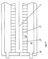
- the lock is in an enlarged view in Figure 2 using a longitudinal section and in Figure 3 can be seen on the basis of a cross section along the line AA of Figure 2.
- a device according to the invention in other words a device according to the invention Steam dryer, has a vapor-tight, heat-insulated housing 1 with an inlet slot 2 and an outlet slot not shown in FIG. 1 and also not shown in FIG. 1 Transport device shown for a in the transport direction 3 through the steam dryer current web 4 on.
- Transport device shown for a in the transport direction 3 through the steam dryer current web 4 on.
- At least one field is a steam field 5 with a device for guiding steam in a circulating air process with a, dashed shown, circulating air fan 6 and a heating device, not shown, and with Nozzle boxes 7 with nozzle openings aimed at the web 4.
- One or more of the remaining fields can be air fields with a device for guiding Mostly heated air in the recirculation process also with a recirculation fan and with Be nozzle boxes with nozzle openings aimed at the material web.
- all six fields are steam fields 5, in each of which several, for Example two, above and below the web 4, across the web 4 extending nozzle boxes 7 are arranged.
- the manifold 9 leads to an exhaust fan 10.
- the inlet slot 2 is on a front wall 11 of the housing 1 and the outlet slot a rear wall of the housing 1 attached.
- the transport device forms inside the Housing 1 for the web 4 a horizontal transport plane on which the inlet slot 2nd and the outlet slot is arranged; d. H. it is designed so that the web 4 through the inlet slot 2, through the housing 1 and through the outlet slot on the horizontal Transport level is guided.
- a transport device with a tension chain through the inlet slot through the housing and through the outlet slot
- Tension chains arranged on a horizontal plane can also have a roller conveyor or a belt. It can also be used to levitate the Have material web, such as nozzle boxes with air cushion nozzles.
- the lock In front of the inlet slot 1 there is a lock with at least one steam chamber 12 Nozzle boxes 13 arranged.
- the lock has a vapor-tight, Heat-insulated housing 14, which is arranged in three in the transport direction 3 one behind the other Chambers, namely an air chamber 15, the steam chamber 12 and a suction chamber 16 is divided on.
- One to a steam exhaust line 8 from another steam field 5, here the second field, connected steam supply line 18 leads through a heat exchanger 19, through which one Air line 20 leads from one with its suction side to the atmosphere outside the Steam dryer open fan 21 goes out and behind the heat exchanger 19 to the Air chamber 15 of the lock is connected.
- a suction line 22 which leads to a fan, not shown leads, connected.
- the chambers 15, 12 and 16 of the lock have nozzle boxes.
- each chamber has a nozzle box 23 which extends over the entire width of the web, 13, 24 arranged in mirror image above and below the guide level of the web 4.
- the nozzle boxes 23, 13, 24 are through the housing 14 of the lock, two each Partitions 25, 26 and their bottom plates 27, 28, 29 are formed. Are on their side walls Openings 30 31, 32 are provided.
- the openings 30 31, 32 of the two opposite Nozzle boxes 23, 13, 24 of a chamber 15, 12, 16 are each, for example, by a line, not shown, connected together. In the respective line can the chambers 15, 12, 16 connected lines, namely the air line 21, the Steam supply line 17 and suction line 22 open out.
- the nozzle boxes 23 and 13 of the air chamber 15 and the steam chamber 12 point to the Floor plates 27, 28 attached slot nozzles 33, 34, the slot nozzles 34 of the Nozzle boxes 13 of the steam chamber 12 at an angle, counter to the transport direction 3 on the Goods web 4 are directed.
- the bottom plate 29 of the suction chamber 16 has Suction openings 35, for example round bores. The bottom plate 29 can be perforated his.
- the slot nozzles 33, 34 each have two side plates 35, 36 and their slots dividing Baffles 37 on.
- the side bleaches 35, 36 extend over a width which is at least that corresponds to the maximum width of the web 4; d. H. usually over the entire length of the Nozzle boxes 23 and 13.
- the guide plates 37 are arranged parallel to the transport direction 3 and divide the slots into equally large flow openings. They serve the purpose of equalization the flow of air and steam onto the web 4.
- the lock with the three chambers 15, 12 and 16 extends over the entire Web width; their length is approximately 1 m and their total height is approximately 0.8 m.
- the steam in the steam fields 5 performed in a circulating air process, with the continuous web 4 through the on Material web 4 directed nozzle openings of the nozzle boxes 7 steam inflated and the Steam after contact with the web 4 as exhaust steam with the help of the air circulation fan dissipated, heated to the desired temperature by the heating device and is fed again.
- the steam is after a start-up phase in which the superheated steam from supplied outside, constantly generated by drying the web 4. It is in Interior of the housing 1 before the inlet slot 2 and before the outlet slot an overpressure maintain.
- a part of the steam is after contact with the web 4 as waste steam through the Steam exhaust lines 8 deducted.
- Steam can be in the steam chamber 12 with the pressure around 0.2 bar, for example 0.5 bar the pressure in the device is inflated.
Landscapes
- Engineering & Computer Science (AREA)
- Textile Engineering (AREA)
- Mechanical Engineering (AREA)
- General Engineering & Computer Science (AREA)
- Treatment Of Fiber Materials (AREA)
- Drying Of Solid Materials (AREA)
Abstract
Description
Die Erfindung betrifft ein Verfahren zum Wärmebehandeln einer Warenbahn durch Aufblasen von Dampf gemäß dem Oberbegriff des Anspruchs 1 und eine entsprechende Vorrichtung gemäß dem Oberbegriff des Anspruchs 9.The invention relates to a method for heat treating a web by inflation of steam according to the preamble of claim 1 and a corresponding device according to the preamble of claim 9.
Bei einem Verfahren zum Wärmebehandeln einer durchlaufenden Warenbahn wird der Dampf im Umluftverfahren durch Düsenkästen auf die Warenbahn aufgeblasen und nach Erwärmung erneut zugeführt. Eine dazu geeignete Vorrichtung, im folgenden Dampftrockner genannt, weist ein dampfdichtes Gehäuse mit einem Einlauf- und einem Auslaufschlitz und eine Transportvorrichtung für die Warenbahn auf. Häufig sind mehrere Behandlungsfelder hinteinander angeordnet, wobei jedes Feld mit einer Vorrichtung zu Zufuhr von Dampf im Umluftverfahren versehen ist.In one method for heat treating a continuous web of material, the steam inflated to the material web by nozzle boxes and after heating fed again. A suitable device, hereinafter called steam dryer, has a vapor-tight housing with an inlet and an outlet slot and one Transport device for the web. There are often several treatment areas arranged one behind the other, each field with a device for supplying steam in the Circulation air process is provided.
Die Wärmebehandlung kann eine Trocknung, eine Trocknung mit einer Fixierung oder eine reine Fixierung umfassen. Dabei können alle Felder des Dampftrockners, oder nur einige der Felder, mit Dampf betrieben werden. Die zu behandelnden, durchlaufenden Warenbahnen sind bevorzugt Textilbahnen. Es können auch Papier- oder Folienbahnen oder dergleichen sein. Die Warenbahnen werden durch eine Transportvorrichtung, zum Beispiel mit Spannketten, mit einem Rollengang oder mit einem Siebband, durch den Dampftrockner gefördert. Die Tranportvorrichtung kann auch mit Luftkissendüsen versehende Düsenkästen zur freischwebenden Führung der Warenbahn aufweisen.The heat treatment can be a drying, a drying with a fixation or a include pure fixation. All fields of the steam dryer, or only some of the Fields that are operated with steam. The continuous webs to be treated are prefers textile webs. It can also be paper or film webs or the like. The Material webs are transported by a transport device, for example with tension chains a roller conveyor or with a screen belt, conveyed through the steam dryer. The Transport device can also be provided with nozzle boxes provided with air cushion nozzles have free-floating guidance of the web.
Die Vorteile einer Wärmbehandlung, insbesondere einer Trocknung mit reinem Heißdampf, wie
die besondere Wirtschaftlichkeit und die Qualitätsverbesserung, sind bereits in dem Buch
![]()
![]()
Bei einer aus der DE 195 46 344 bekannten gattungsgemäßen Vorrichtung und einem entsprechenden Verfahren wird das Eindringen von Luft weitgehend unterdrückt, indem alle kritischen Stellen in den Boden des Gehäuses verlegt sind und beiderseits des Einlaufschlitzes und des Auslaufschlitzes in das Gehäuse ragende Saugkästen angeordnet sind. Der Dampf erzeugt im gesamten Innenraum des Gehäuses einen Überdruck, der in der Nähe des Bodens besonders hoch ist. Auch in den Bereichen, die saugseitig mit Gebläsen in Verbindung stehen stellt sich relativ zur Atmosphäre ein geringer Überdruck ein. Überschußdampf entweicht durch den Einlaufschlitz und den Auslaufschlitz und wird durch die Saugkästen abgezogen.In a generic device known from DE 195 46 344 and a corresponding procedure, the penetration of air is largely suppressed by all critical points are laid in the bottom of the housing and on both sides of the inlet slot and the outlet slot are arranged in the housing projecting suction boxes. The steam creates an overpressure in the entire interior of the housing, which is near the bottom is particularly high. Also in the areas that are connected to fans on the suction side there is a slight overpressure relative to the atmosphere. Excess steam escapes through the inlet slot and the outlet slot and is withdrawn through the suction boxes.
Problematisch ist, daß die durch den Einlaufschlitz geförderte Warenbahn wesentlich kälter ist, als der Dampf im Innenraum des Gehäuses. Dadurch kann es zu einer unerwünschten Kondensation des Dampfes im Eingangsbereich kommen.The problem is that the material web conveyed through the inlet slot is significantly colder, than the steam inside the case. This can lead to an undesirable Steam condensation in the entrance area.
Aus der DE 27 27 971 ist eine Vorrichtung zum thermischen Behandeln einer kontinuierlich bewegten Warenbahn bekannt, bei der zur Reduzierung des Eintritts von Raumluft in eine Behandlungskammer auf der Außenseite von in einer Wand der Behandlungskammer vorgesehenen Warenbahnein- und austrittsöffnungen je ein Düsensystem als Dichtung vorgesehen ist. Ein Düsensystem enthält ein der Kammeröffnung benachbartes erstes Düsenpaar, das mit einer an Unterdruck liegenden Stelle der Behandlungskammer verbunden ist, sowie ein hierauf folgendes zweites Düsenpaar, das mit der Druckseite eines saugseitig an Atmosphäre angeschlossenen Ventilators verbunden ist.DE 27 27 971 describes a device for the thermal treatment of a continuous moving web of goods known to reduce the entry of indoor air into a Treatment chamber on the outside of in a wall of the treatment chamber provided web inlet and outlet openings each have a nozzle system as a seal is provided. A nozzle system includes a first one adjacent the chamber opening A pair of nozzles connected to a point in the treatment chamber which is at a negative pressure is, as well as a subsequent second pair of nozzles, with the pressure side of a suction side Atmosphere connected fan is connected.
Die Anordnung eines aus der DE-A 27 27 971 bekannten Düsensystem in einem Dampftrockner vorzusehen, ist schon deshalb nicht möglich, weil im Dampftrockner mit Überdruck gearbeitet werden soll. Insbesondere würden Stellen im Innern eines Dampftrockners mit Unterdruck die Gefahr von Leckströmen erhöhen. Durch die Verbindung eines ersten Düsenpaars mit einer an Unterdruck liegenden Stelle im Dampftrockner würde Luft, die über den Ventilator aus der Atmosphäre angesaugt und im zweiten Düsenpaar zugeführt wird, in den Dampftrockner gelangen. Ein Eindringen von Raumluft könnte daher nicht sicher verhindert werden. Nachteilig ist auch, daß die durch die Warenbahneintrittöffnung geförderte, kühle Warenbahn ebenfalls eine unerwünschte Kondensation des Dampfes verursachen würde.The arrangement of a nozzle system known from DE-A 27 27 971 in one It is not possible to provide a steam dryer simply because in the steam dryer Overpressure should be worked. In particular, places inside a Steam dryers with negative pressure increase the risk of leakage currents. Through the connection of a first pair of nozzles with a point in the steam dryer located at negative pressure Air drawn in from the atmosphere via the fan and in the second pair of nozzles is fed, get into the steam dryer. A penetration of room air could therefore cannot be prevented safely. Another disadvantage is that through the web entrance opening promoted, cool web also undesirable condensation of the steam would cause.
Eine weitere Trocknungsanlage, und zwar für Papierbahnen, ist aus der DE-A 42 26 107 bekannt. Diese Trocknungsanlage weist einen Trockner mit zusätzlichen Düsenkästen beiderseits des Eintritts- und des Austrittsschlitzes auf. Zu den Düsenkästen sind Zuleitungen für vorgewärmte Behandlungsluft geführt. Die Düsenkästen sind mit Düsenöffnungen versehen, deren Blasrichtung spitzwinklig zur Bahnführungsebene auf den Eintrittsspalt gerichtet ist. Dazu sind die Düsenkästen im Schnitt sägezahnförmig profiliert. Das Eindringen von kalter Umgebungsluft durch den Eintrittsschlitz soll sich durch eine passende Abstimmung zwischen Austrittsgeschwindigkeit der Blasstrahlen und dem im Innern des Trockners bestehenden Unterdruck unterbinden lassen. Der Unterdruck verhindert das Entweichen von beim Trocknen flüchtig werdenden Lösemitteln. Im Gegensatz dazu soll ein Dampftrockner im Überdruck betrieben werden. Daher kann das aus der DE-A 42 26 107 bekannte Verfahren, das eine Vorwärmung der Warenbahn und eine Unterbindung des Eindringens von kalter Umgebungsluft ermöglicht, nicht für einen Dampftrockner angewandt werden. Nachteilig ist insbesondere, daß in jedem Fall vorgewärmte Behandlungsluft in den Trockner eindringt. In einen Dampftrockner sollte überhaupt keine Luft eindringen.Another drying installation, namely for paper webs, is from DE-A 42 26 107 known. This drying system has a dryer with additional nozzle boxes on both sides of the entry and exit slots. There are supply lines to the nozzle boxes led for preheated treatment air. The nozzle boxes are provided with nozzle openings, the blowing direction of which is directed at an acute angle to the web guide plane onto the inlet gap. To the nozzle boxes are sawtooth-shaped on average. The penetration of cold Ambient air through the inlet slit is supposed to be matched between Exit velocity of the blowing jets and that existing inside the dryer Have negative pressure prevented. The vacuum prevents it from escaping when drying volatile solvents. In contrast, a steam dryer should be at overpressure operate. Therefore, the method known from DE-A 42 26 107, the one Preheating the web and preventing the ingress of cold ambient air allows not to be applied for a steam dryer. A particular disadvantage is that in any case, preheated treatment air penetrates into the dryer. In a steam dryer no air should enter at all.
Eine sich von den Vorrichtungen zur Wärmebehandlung durchlaufender Bahnen
unterscheidende Wärmebehandlungsvorrichtung, nämlich ein Hängeschleifendämpfer, bei dem
die Warenbahn mittels an einer umlaufenden Kette befestigten Tragstäben in frei hängenden
Schleifen durch die Behandlung geführt wird, ist aus der DE 29 51 299 bekannt. Dieser
Hängeschleifendämpfer ist an seinem im Boden befindlichen Einführschlitz mit einer Luft- bzw.
Dampfschleuse versehen. Über den Aufbau und das Betreiben der Schleuse sind keine
Angaben gemacht. Im Gegensatz zu einem gattungsgemäßen Dampftrockner, bei dem der
Dampf auf eine kontinuierlich bewegte Warenbahn aufgeblasen und ständig umgewälzt wird, ist
die Dampfströmung und auch die Warenbahngeschwindigkeit in einem Hängeschleifendämpfer
wesentlich geringer, d.h. auch die Anforderungen an eine Schleuse sind geringer.A path running through the devices for heat treatment
distinguishing heat treatment device, namely a hanging loop damper, in which
the material web by means of supporting rods attached to a circulating chain in free hanging
Grinding through the treatment is known from
Aufgabe der Erfindung ist, ein gattungsgemäßes Verfahren zum Wärmebehandeln einer durchlaufenden Warenbahn durch Aufblasen von Dampf gemäß dem Oberbegriff des Anspruchs 1 und eine entsprechende gattungsgemäße Vorrichtung gemäß dem Oberbegriff des Anspruchs 9 so weiterzuentwickeln, daß möglichst keine Luft, weder Luft mit Umgebungstemperatur noch erwärmte Luft, in das Innere der Vorrichtung eindringt. Außerdem sollte eine Kondensation des Dampfes im Eingangsbereich an der Warenbahn vermieden werden.The object of the invention is a generic method for heat treating a continuous web of goods by inflating steam according to the preamble of Claim 1 and a corresponding generic device according to the preamble of claim 9 to develop so that if possible no air, neither air with Ambient temperature still heated air penetrates into the interior of the device. Moreover should avoid condensation of the steam in the entrance area on the web become.
Die Aufgabe wird durch die kennzeichnenden Merkmale der Ansprüche 1 und 9 gelöst.The object is achieved by the characterizing features of claims 1 and 9.
Erfindungsgemäß wird zusätzlich Dampf in einer Schleuse vor dem Einlaufschlitz des Gehäuses auf die Warenbahn aufgeblasen. Durch den Dampf wird die die Warenbahn umgebende Luft verdrängt, wodurch ein Eindringen von Luft in das Innere des Gehäuses verhindert wird. Außerdem wird die Warenbahn durch den aufgeblasenen Dampf durch die große Wärmekapazität des Dampfes mit hoher Effizienz aufgewärmt. Dies reduziert die Gefahr einer Kondensatbildung im Eingangsbereichs im Innern des Gehäuses.According to the invention, steam is additionally in a lock in front of the inlet slot of the Inflated housing on the web. The steam becomes the web surrounding air displaces, causing air to enter the interior of the housing is prevented. In addition, the web is inflated by the steam through the large heat capacity of the steam warmed up with high efficiency. This reduces the risk formation of condensate in the entrance area inside the housing.
Eine Dampfgeschwindigkeit von 20 bis 40 m/s gemäß Anspruch 2 stellt sicher, daß der auf die
Warenbahn auftreffende Dampf die Luftgrenzschicht verdrängt und der Eintritt von Luft in das
Gehäuse vermieden wird. A steam speed of 20 to 40 m / s according to
Im Gegensatz zudem aus der DE 195 46 344 bekannten Verfahren, bei dem die Warenbahn
durch den Boden in das Gehäuse hinein und aus dem Gehäuse hinausgeführt wird, ermöglicht
das erfindungsgemäße Aufblasen von Dampf in der Schleuse eine horizontale Führung der
Warenbahn gemäß Anspruch 3. Dabei wird die Warenbahn in einer im wesentlichen
horizontalen Ebene durch den Einlaufschlitz, das Gehäuse und den Auslaufschlitz hindurch
gefördert. Eine horizontale Warenbahnführung vereinfacht die Transportvorrichtung und
verbessert die Zugangsmöglichkeit der Warenbahn am Eintritt in das Gehäuse und an ihrem
Austritt. Eventuelle Ungleichmäßigkeiten auf der Warenbahn, die durch ihre Umlenkung beim
Ein- und Austritt durch den Boden entstehen können, werden vermieden.In contrast, in addition, known from DE 195 46 344, in which the web
through the bottom into and out of the housing
the inflation of steam according to the invention in the lock a horizontal guidance of the
Material web according to
Vorteilhafterweise wird gemäß Anspruch 4 ein Teil des Abdampfes in der Schleuse zuzuführen.
Dies erspart eine zusätzliche Dampfquelle.Advantageously, part of the exhaust steam is fed into the lock according to
Abdampf, der gemäß Anspruch 5 aus dem vorderen Bereich der Vorrichtung entnommen wird,
ist nicht oder wesentlich weniger mit Ölen der Präparationsmittel kontaminiert als solcher aus
dem hinteren Bereich der Vorrichtung.Exhaust steam, which is removed according to
Gemäß Anspruch 6 wird in der Schleuse vor dem Aufblasen von Dampf erwärmte Luft auf die
Warenbahn aufgeblasen. Dies führt zu einer Vorerwärmung der Warenbahn und verhindert die
Berührung von aus der Schleuse austretenden Dampfes mit kalter Umgebungsluft, was zu einer
Kondensation des Dampfes führen würde.According to
Gemäß Anspruch 7 kann vor dem Auf blasen von Dampf ggf. nach dem Aufblasen von
erwärmter Luft und/oder hinter dem Aufblasen von Dampf in der Schleuse Gas abgesaugt
werden. Das Absaugen des Gases, d. h. der ggf. erwärmten Luft oder des Dampfes vergrößert
die Sicherheit, daß keine Luft in das Innere des Dampftrockners eindringt. Ein Absaugen des
Dampfes hinter der Dampfzufuhr ermöglicht ein Aufblasen von Dampf mit höherem Druck.According to
Gemäß Anspruch 8 wird in der Schleuse bevorzugt zunächst erwärmte Luft, dahinter Dampf
aufgeblasen und anschließend der Dampf abgesaugt. Dabei kann der in der Schleuse
zugeführte Dampf mit einem Druck, der dem im Innern des Dampftrockners entspricht,
zugeführt werden.
Schlitzdüsen gemäß Anspruch 16 ermöglichen einen besonders intensiven Kontakt des Dampfes bzw. der erwärmten Luft mit der Warenbahn und einen guten Wärmeübergang.Slot nozzles according to claim 16 allow a particularly intensive contact of the Steam or the heated air with the web and good heat transfer.
Die Erfindung wird anhand eines in der Zeichnung schematisch dargestellten Beispiels weiter erläutert.The invention is further illustrated by an example shown schematically in the drawing explained.
Figur 1 zeigt die schematische Darstellung einer Seitenansicht der ersten drei Felder eines erfindungsgemäßen Dampftrockners mit einer Schleuse und die mit der Schleuse verbundenen Leitungen.Figure 1 shows the schematic representation of a side view of the first three fields Steam dryer according to the invention with a lock and those connected to the lock Cables.
Die Schleuse ist in einer vergrößerten Darstellung in Figur 2 anhand eines Längsschnitt und in Figur 3 anhand eines Querschnitts gemäß der Linie AA der Figur 2 zu sehen.The lock is in an enlarged view in Figure 2 using a longitudinal section and in Figure 3 can be seen on the basis of a cross section along the line AA of Figure 2.
Eine erfindungsgemäße Vorrichtung, mit anderen Worten ein erfindungsgemäßer
Dampftrockner, weist ein dampfdichtes, wärmeisoliertes Gehäuse 1 mit einem Einlaufschlitz 2
und einem in Figur 1 nicht dargestellten Auslaufschlitz und eine ebenfalls in Figur 1 nicht
dargestellte Transportvorrichtung für eine in Transportrichtung 3 durch den Dampftrockner
laufende Warenbahn 4 auf. Es sind mehrere, zum Beispiel sechs Felder, von denen in Figur 1
drei zu sehen sind, hintereinander angeordnet. Mindestens ein Feld ist ein Dampffeld 5 mit
einer Vorrichtung zum Führen von Dampf im Umluftverfahren mit einem, gestrichelt
eingezeichneten, Umluftventilator 6 und einer nicht dargestellten Heizeinrichtung und mit
Düsenkästen 7 mit auf die Warenbahn 4 zielenden Düsenöffnungen.A device according to the invention, in other words a device according to the invention
Steam dryer, has a vapor-tight, heat-insulated housing 1 with an
Eines oder mehrere der übrigen Felder können Luftfelder mit einer Vorrichtung zum Führen von zumeist erhitzter Luft im Umluftverfahren ebenfalls mit einem Umluftventilator und mit Düsenkästen mit auf die Warenbahn zielenden Düsenöffnungen sein.One or more of the remaining fields can be air fields with a device for guiding Mostly heated air in the recirculation process also with a recirculation fan and with Be nozzle boxes with nozzle openings aimed at the material web.
In diesem Beispiel sind alle sechs Felder Dampffelder 5, in denen jeweils mehrere, zum
Beispiel zwei, oberhalb und unterhalb der Warenbahn 4, sich quer über die Warenbahn 4
erstreckende Düsenkästen 7 angeordnet sind. Von jedem Dampffeld 5 geht eine
Dampfabzugleitung 8 aus, wobei die Dampfabzugleitungen 8 der hinteren Feldern in eine
Sammelleitung 9 münden. Die Sammelleitung 9 führt zu einem Abzugventilator 10. In this example, all six fields are
Der Einlaufschlitz 2 ist an einer Vorderwand 11 des Gehäuses 1 und der Austrittsschlitz an
einer Hinterwand des Gehäuses 1 angebracht. Die Transportvorrichtung bildet im Innern des
Gehäuses 1 für die Warenbahn 4 eine horizontale Transportebene, auf der der Einlaufschlitz 2
und der Auslaufschlitz angeordnet ist; d. h. sie ist so ausgebildet, daß die Warenbahn 4 durch
den Einlaufschlitz 2, durch das Gehäuse 1 und durch den Auslaufschlitz auf der horizontalen
Transportebene geführt ist. Beispielsweise sind bei einer Transportvorrichtung mit Spannkette
die durch den Einlaufschlitz, durch das Gehäuse und durch den Auslaufschlitz verlaufenden
Spannketten auf einer horizontalen Ebenen angeordnet. Die Transportvorrichtung kann auch
einen Rollengang oder ein Siebband aufweisen. Sie kann auch Mittel zum Freischweben der
Warenbahn, wie Düsenkästen mit Luftkissendüsen, aufweisen.The
Vor dem Einlaufschlitz 1 ist eine Schleuse mit mindestens einer Dampfkammer 12 mit
Düsenkästen 13 angeordnet. In diesem Beispiel weist die Schleuse ein dampfdichtes,
wärmeisoliertes Gehäuse 14, das in drei in Transportrichtung 3 hintereinander angeordnete
Kammern, nämlich eine Luftkammer 15, die Dampfkammer 12 und eine Absaugkammer 16
unterteilt ist, auf.In front of the inlet slot 1 there is a lock with at least one
An die Dampfkammer 12 ist eine mit einer Dampfabzugleitung 8 eines vorderen Dampffeldes 5,
hier des ersten Feldes, verbundene Dampfzuleitung 17 angeschlossen.To the
Eine an eine Dampfabzugleitung 8 eines anderen Dampffeldes 5, hier des zweiten Feldes,
angeschlossene Dampfzuleitung 18 führt durch einen Wärmetauscher 19, durch den auch eine
Luftleitung 20 führt, die von einem mit seiner Saugseite zur Atmosphäre außerhalb des
Dampftrockners offenen Ventilator 21 ausgeht und hinter dem Wärmetauscher 19 an die
Luftkammer 15 der Schleuse angeschlossen ist.One to a
An die Absaugkammer 16 ist eine Absaugleitung 22, die zu einem nicht dargestellten Ventilator
führt, angeschlossen.At the
Die Kammern 15, 12 und 16 der Schleuse weisen Düsenkästen auf. In diesem Beispiel ist in
jeder Kammer je ein, sich über die gesamte Warenbahnbreite erstreckender Düsenkasten 23,
13, 24 spiegelbildlich oberhalb und unterhalb der Führungsebene der Warenbahn 4 angeordnet.
Die Düsenkästen 23, 13, 24 werden durch das Gehäuse 14 der Schleuse, je zwei
Zwischenwände 25, 26 und ihre Bodenbleche 27, 28, 29 gebildet. An ihren Seitenwänden sind
Öffnungen 30 31, 32 vorgesehen sind. Die Öffnungen 30 31, 32 der beiden gegenüberliegenden
Düsenkästen 23, 13, 24 einer Kammer 15, 12, 16 sind jeweils, zum Beispiel durch
eine nicht dargestellte Leitung, miteinander verbunden. In die jeweilige Leitung können die an
die Kammern 15, 12, 16 angeschlossenen Leitungen, nämlich die Luftleitung 21, die
Dampfzuleitung 17 und Absaugleitung 22 münden.The
Die Düsenkästen 23 und 13 der Luftkammer 15 und der Dampfkammer 12 weisen an den
Bodenblechen 27, 28 befestigte Schlitzdüsen 33, 34 auf, wobei die Schlitzdüsen 34 der
Düsenkästen 13 der Dampfkammer 12 schräg, entgegen der Transportrichtung 3 auf die
Warenbahn 4 gerichtet sind. Das Bodenblech 29 der Absaugkammer 16 weist
Ansaugöffnungen 35, beispielsweise runde Bohrungen, auf. Das Bodenblech 29 kann perforiert
sein.The
Die Schlitzdüsen 33, 34 weisen jeweils zwei Seitenbleche 35, 36 und ihre Schlitze unterteilende
Leitbleche 37 auf. Die Seitenbleiche 35, 36 erstrecken sich über eine Breite, die mindestens der
maximalen Breite der Warenbahn 4 entspricht; d. h. üblicherweise über die gesamte Länge der
Düsenkästen 23 und 13. Die Leitbleche 37 sind parallel zur Transportrichtung 3 angeordnet und
unterteilen die Schlitze in gleich große Strömungsöffnungen. Sie dienen der Vergleichmäßigung
der Strömung der Luft und des Dampfes auf die Warenbahn 4.The slot nozzles 33, 34 each have two
Die Schleuse mit den drei Kammern 15, 12 und 16 erstreckt sich über die gesamte
Warenbahnbreite; ihre Länge beträgt etwa 1 m und ihre gesamte Höhe etwa 0,8 m.The lock with the three
Bei einem erfindungsgemäßen Verfahren zum Trocknen wird der Dampf in den Dampffeldern 5
im Umluftverfahren geführt, wobei auf die durchlaufende Warenbahn 4 durch die auf die
Warenbahn 4 gerichteten Düsenöffnungen der Düsenkästen 7 Dampf aufgeblasen und der
Dampf nach Kontakt mit der Warenbahn 4 als Abdampf mit Hilfe des Umluftventilators
abgeführt, durch die Heizeinrichtung wieder auf die gewünschte Temperatur erwärmt und
erneut zugeführt wird. Der Dampf wird nach einer Anfahrphase, in der der Heißdampf von
außen zugeführt wird, ständig durch Trocknung der Warenbahn 4 erzeugt. Dabei wird im
Innenraum des Gehäuses 1 vor dem Einlaufschlitz 2 und vor dem Auslaufschlitz ein Überdruck
aufrechterhalten.In a method for drying according to the invention, the steam in the steam fields 5
performed in a circulating air process, with the
Ein Teil des Dampfes wird nach dem Kontakt mit der Warenbahn 4 als Abdampf durch die
Dampfabzugleitungen 8 abgezogen. Durch Steuerung der Menge des abgezogenen
Abdampfes kann die aus dem Einlaufschlitz und aus dem Auslaufschlitz ausgetretene
Dampfmenge auf bestimmten Werten gehalten werden.A part of the steam is after contact with the
In der Schleuse vor dem Einlaufschlitz 2 wird in der Dampfkammer 12 gleichmäßig durch die
Schlitzdüsen 34 Dampf auf die Warenbahn 3 aufgeblasen. Dieser Dampf ist ein Teilstrom des
nach dem Kontakt mit der Warenbahn 4 als Abdampf aus den Dampffeldern 5 abgezogenen
Abdampfes, und zwar ein Teilstrom des aus dem ersten Dampffeld 5 abgezogenen und über
die Dampfzuleitung 17 zugeführten Abdampfes.In the lock in front of the
In der Schleuse wird vor der Zufuhr von Dampf in der vorgelagerten Luftkammer 15 auf die
Warenbahn 4 gleichmäßig durch die Schlitzdüsen 33 erwärmte Luft aufgeblasen. Die erwärmte
Luft wird durch Erwärmen von Frischluft in dem mit Abdampf des zweiten Dampffeldes 5
gespeisten Wärmetauscher 19 erzeugt.In the lock is before the supply of steam in the
Anschließend an die Zufuhr von erwärmter Luft und die Zufuhr von Dampf wird in der
Absaugkammer 16 der Schleuse vor dem Einlaufschlitz 2 Dampf aus der Dampfkammer 12 und
Dampf aus dem Inneren der Gehäuses 1 in die Absaugkammer 16 abgesaugt.Subsequent to the supply of heated air and the supply of steam is in the
Dampf kann in der Dampfkammer 12 mit dem Druck der um 0,2 bar, zum Beispiel 0,5 bar, über
den Druck in der Vorrichtung liegt, aufgeblasen werden. Steam can be in the
- 11
- Gehäusecasing
- 22nd
- EinlaufschlitzInlet slot
- 33rd
- TransportrichtungDirection of transport
- 44th
- WarenbahnGoods web
- 55
- DampffeldSteam field
- 66
- UmluftventilatorAir circulation fan
- 77
- DüsenkastenNozzle box
- 88th
- DampfabzugleitungSteam exhaust line
- 99
- SammelleitungManifold
- 1010th
- AbzugventilatorExtractor fan
- 1111
- VorderwandFront wall
- 1212th
- DampfkammerSteam chamber
- 1313
- DüsenkastenNozzle box
- 1414
- Gehäuse der SchleuseLock housing
- 1515
- LuftkammerAir chamber
- 1616
- AbsaugkammerSuction chamber
- 1717th
- DampfzuleitungSteam supply
- 1818th
- DampfzuleitungSteam supply
- 1919th
- WärmetauscherHeat exchanger
- 2020th
- LuftleitungAir duct
- 2121
- Ventilatorfan
- 2222
- AbsaugleitungSuction line
- 2323
- DüsenkastenNozzle box
- 2424th
- DüsenkastenNozzle box
- 2525th
- ZwischenwandPartition
- 2626
- ZwischenwandPartition
- 2727
- BodenblechFloor panel
- 2828
- BodenblechFloor panel
- 2929
- BodenblechFloor panel
- 3030th
- Öffnungopening
- 3131
- Öffnungopening
- 3232
- Öffnungopening
- 3333
- SchlitzdüseSlot nozzle
- 3434
- SchlitzdüseSlot nozzle
- 3535
- SeitenblechPage sheet
- 3636
- SeitenblechPage sheet
- 3737
- LeitblechBaffle
Claims (16)
wobei im Gehäuse ein Überdruck aufrecht erhalten wird,
dadurch gekennzeichnet, daß
whereby an overpressure is maintained in the housing,
characterized in that
dadurch gekennzeichnet, daß
characterized in that
Priority Applications (1)
| Application Number | Priority Date | Filing Date | Title |
|---|---|---|---|
| DK99122120T DK1010959T3 (en) | 1998-12-19 | 1999-11-05 | Method and apparatus for heat treating a running goods web by blowing steam |
Applications Claiming Priority (2)
| Application Number | Priority Date | Filing Date | Title |
|---|---|---|---|
| DE19858839A DE19858839B4 (en) | 1998-12-19 | 1998-12-19 | Method and apparatus for heat treating a continuous web by blowing steam |
| DE19858839 | 1998-12-19 |
Publications (3)
| Publication Number | Publication Date |
|---|---|
| EP1010959A2 true EP1010959A2 (en) | 2000-06-21 |
| EP1010959A3 EP1010959A3 (en) | 2001-09-12 |
| EP1010959B1 EP1010959B1 (en) | 2005-03-16 |
Family
ID=7891820
Family Applications (1)
| Application Number | Title | Priority Date | Filing Date |
|---|---|---|---|
| EP99122120A Expired - Lifetime EP1010959B1 (en) | 1998-12-19 | 1999-11-05 | Process and apparatus for the heat treatment of a running web by blowing with vapour |
Country Status (5)
| Country | Link |
|---|---|
| US (1) | US6282811B1 (en) |
| EP (1) | EP1010959B1 (en) |
| AT (1) | ATE291211T1 (en) |
| DE (2) | DE19858839B4 (en) |
| DK (1) | DK1010959T3 (en) |
Cited By (1)
| Publication number | Priority date | Publication date | Assignee | Title |
|---|---|---|---|---|
| EP1055763A2 (en) * | 1999-05-28 | 2000-11-29 | Babcock Textilmaschinen GmbH | Method and device for the continuous steam treatment of a textile fabric to fix reactive dyestuffs on natural fibres |
Families Citing this family (11)
| Publication number | Priority date | Publication date | Assignee | Title |
|---|---|---|---|---|
| DE29909402U1 (en) | 1999-05-31 | 1999-08-12 | Babcock Textilmaschinen GmbH, 21220 Seevetal | Superheated steam dryer |
| US6631566B2 (en) * | 2000-09-18 | 2003-10-14 | Kimberly-Clark Worldwide, Inc. | Method of drying a web |
| DE10333483B4 (en) | 2003-07-22 | 2008-11-27 | Moenus Textilmaschinen Gmbh | Process for heat treatment of a web and treatment device |
| DE10337644B3 (en) * | 2003-08-16 | 2005-05-25 | Elpo Gmbh Luft- Und Trocknungstechnik | Heat treatment device for strip material has furnace with positive and negative pressure chambers on opposite sides of strip material |
| SE536108C2 (en) * | 2010-11-16 | 2013-05-07 | Andritz Tech & Asset Man Gmbh | Drying box comprising at least two zones for drying a cellulose pulp web |
| US9217212B2 (en) * | 2011-01-21 | 2015-12-22 | Despatch Industries Limited Partnership | Oven with gas circulation system and method |
| CN104088110B (en) * | 2014-07-18 | 2016-04-27 | 苏州市宏达集团有限公司 | A kind of steam forming machine |
| CN105318689B (en) * | 2015-10-12 | 2017-12-19 | 江苏广盛源科技发展有限公司 | A kind of equipment and furnace drying method for textile drying |
| CN105318690B (en) * | 2015-10-12 | 2017-12-15 | 盐城帝佳妮服饰有限公司 | A kind of equipment and furnace drying method for textile drying |
| CN105318687B (en) * | 2015-10-12 | 2017-12-15 | 江苏广盛源科技发展有限公司 | A kind of equipment and furnace drying method for textile drying |
| CN108589130A (en) * | 2018-05-16 | 2018-09-28 | 湖州织里创塑塑料科技有限公司 | A kind of steaming cloth machine |
Citations (3)
| Publication number | Priority date | Publication date | Assignee | Title |
|---|---|---|---|---|
| DE2727971A1 (en) | 1977-06-22 | 1979-01-11 | Brueckner Apparatebau Gmbh | Fabric heat treatment - waste gas extracted as first stream for cleaning and reheating by burning second stream |
| DE4226107A1 (en) | 1992-08-07 | 1994-02-10 | Vits Maschinenbau Gmbh | Drying plant |
| DE19546344A1 (en) | 1995-12-12 | 1997-06-19 | Babcock Textilmasch | Device for the heat treatment of continuous material webs |
Family Cites Families (15)
| Publication number | Priority date | Publication date | Assignee | Title |
|---|---|---|---|---|
| DE1460574A1 (en) * | 1964-03-18 | 1969-09-04 | Fleissner Gmbh | Sealing at the inlet and outlet of pressure chambers in textile treatment plants |
| US3577653A (en) * | 1970-01-20 | 1971-05-04 | Beloit Corp | Web drying tunnel |
| DE2310195C2 (en) * | 1973-02-02 | 1983-01-20 | Vepa AG, 4125 Riehen, Basel | Damper with at least partially horizontal goods guidance |
| DE2951299A1 (en) | 1979-12-20 | 1981-07-09 | Babcock Textilmaschinen Kg (Gmbh & Co), 2105 Seevetal | HEAT TREATMENT DEVICE, IN PARTICULAR HINGED LOOP DAMPER |
| GB2079913A (en) * | 1980-05-09 | 1982-01-27 | Crosfield Electronics Ltd | Web drying apparatus |
| DE3038791C2 (en) * | 1980-10-14 | 1985-08-01 | Lohmann Gmbh & Co Kg, 5450 Neuwied | Device for drying solvent-based material |
| DE3315755A1 (en) * | 1983-04-30 | 1984-10-31 | Babcock Textilmaschinen GmbH, 2105 Seevetal | FIBER CATALOG INBES. FOR TEXTILE DRYERS AND THE LIKE |
| GB8405716D0 (en) * | 1984-03-05 | 1984-04-11 | Reed C M | Heat treatment apparatus |
| DE3743598A1 (en) * | 1987-12-22 | 1989-07-13 | Kramer Carl | DEVICE FOR CONTACT-FREE SEALING AN OPENING AGAINST LEAKING OR INLETING GAS |
| FI78756C (en) * | 1988-04-25 | 1989-09-11 | Valmet Paper Machinery Inc | Method and apparatus for drying a moving web |
| JP2552929B2 (en) * | 1990-02-20 | 1996-11-13 | 富士写真フイルム株式会社 | Gas seal device for the web penetration part of the processing chamber wall |
| DE4033637A1 (en) * | 1990-10-23 | 1992-04-30 | Babcock Textilmasch | Device for circulating control air in heat treatment plant - involves nozzle bodies above and below material track, working from common blower |
| US5105558A (en) * | 1991-03-28 | 1992-04-21 | Curry Donald P | Apparatus and process for drying cellulosic and textile substances with superheated steam |
| US5429303A (en) * | 1993-03-20 | 1995-07-04 | V.I.B. Apparatebau Gmbh | Steam spray tube with linear acceleration channel |
| DE19525545C1 (en) * | 1995-07-13 | 1996-09-26 | Babcock Textilmasch | Compact drier for high throughput for textile web with heavy borders |
-
1998
- 1998-12-19 DE DE19858839A patent/DE19858839B4/en not_active Expired - Fee Related
-
1999
- 1999-11-05 DK DK99122120T patent/DK1010959T3/en active
- 1999-11-05 EP EP99122120A patent/EP1010959B1/en not_active Expired - Lifetime
- 1999-11-05 AT AT99122120T patent/ATE291211T1/en not_active IP Right Cessation
- 1999-11-05 DE DE59911760T patent/DE59911760D1/en not_active Expired - Fee Related
- 1999-12-14 US US09/460,695 patent/US6282811B1/en not_active Expired - Fee Related
Patent Citations (3)
| Publication number | Priority date | Publication date | Assignee | Title |
|---|---|---|---|---|
| DE2727971A1 (en) | 1977-06-22 | 1979-01-11 | Brueckner Apparatebau Gmbh | Fabric heat treatment - waste gas extracted as first stream for cleaning and reheating by burning second stream |
| DE4226107A1 (en) | 1992-08-07 | 1994-02-10 | Vits Maschinenbau Gmbh | Drying plant |
| DE19546344A1 (en) | 1995-12-12 | 1997-06-19 | Babcock Textilmasch | Device for the heat treatment of continuous material webs |
Cited By (2)
| Publication number | Priority date | Publication date | Assignee | Title |
|---|---|---|---|---|
| EP1055763A2 (en) * | 1999-05-28 | 2000-11-29 | Babcock Textilmaschinen GmbH | Method and device for the continuous steam treatment of a textile fabric to fix reactive dyestuffs on natural fibres |
| EP1055763A3 (en) * | 1999-05-28 | 2002-01-30 | Babcock Textilmaschinen GmbH | Method and device for the continuous steam treatment of a textile fabric to fix reactive dyestuffs on natural fibres |
Also Published As
| Publication number | Publication date |
|---|---|
| US6282811B1 (en) | 2001-09-04 |
| DE19858839B4 (en) | 2005-02-10 |
| EP1010959B1 (en) | 2005-03-16 |
| EP1010959A3 (en) | 2001-09-12 |
| DE59911760D1 (en) | 2005-04-21 |
| DE19858839A1 (en) | 2000-06-21 |
| ATE291211T1 (en) | 2005-04-15 |
| DK1010959T3 (en) | 2005-07-04 |
Similar Documents
| Publication | Publication Date | Title |
|---|---|---|
| EP0448983B1 (en) | Apparatus for blowing onto the two sides of a web-like material | |
| EP1010959B1 (en) | Process and apparatus for the heat treatment of a running web by blowing with vapour | |
| DE3910898A1 (en) | METHOD AND DEVICE IN A COMBINATION DRYER CONSISTING OF A GAS INFRARED ARRANGEMENT AND A SWIRL ARRANGEMENT | |
| DE2659736A1 (en) | EXTRACTION DEVICES FOR MACHINERY | |
| DE60006212T2 (en) | PRODUCT GAS TREATMENT APPARATUS | |
| DE3890457C2 (en) | Web drying method | |
| EP1746191A2 (en) | Method and device for the continuous steam treatment of a textile fabric to fix reactive dyestuffs on natural fibres | |
| DE102013015841B4 (en) | Oxidation furnace | |
| WO2002093098A1 (en) | Gas seal for reactors using gas conducting bodies | |
| EP3632640B1 (en) | Treatment plant for a flexible material sheet which can be passed through a treatment furnace, especially a plastic film | |
| WO1994004740A1 (en) | Blowing device for textile webs | |
| DE2723222A1 (en) | METHOD AND DEVICE FOR DRYING SOLVENT TREATED ITEMS | |
| EP0141227B1 (en) | Vertical dryer | |
| EP0471162B1 (en) | Convective drying and/or fixing apparatus | |
| EP2601467B1 (en) | Apparatus for the heat treatment of a web of textile material | |
| EP0779486A1 (en) | Apparatus for heat treatment of running webs | |
| EP3719430A1 (en) | Continuous flow drying system and method for drying workpieces | |
| EP0658427B1 (en) | Curing apparatus | |
| EP3765807A1 (en) | Method and device for drying sheets | |
| DE1635346A1 (en) | Method and device for heat treatment, in particular of textile goods | |
| EP0586784A1 (en) | Apparatus for the formation of an air flow system for the treatment of running web-like material | |
| EP0063642B1 (en) | Apparatus for hot-air drying of textile materials | |
| EP4185825A1 (en) | Dryer for drying veneer panels | |
| DE19934487A1 (en) | Continuous dryer for panels or webs | |
| DE2302107A1 (en) | Continuous flow dryer for fabrics - with heat exchangers mounted in supports of fan housing |
Legal Events
| Date | Code | Title | Description |
|---|---|---|---|
| PUAI | Public reference made under article 153(3) epc to a published international application that has entered the european phase |
Free format text: ORIGINAL CODE: 0009012 |
|
| AK | Designated contracting states |
Kind code of ref document: A2 Designated state(s): AT BE CH CY DE DK ES FI FR GB GR IE IT LI LU MC NL PT SE |
|
| AX | Request for extension of the european patent |
Free format text: AL;LT;LV;MK;RO;SI |
|
| PUAL | Search report despatched |
Free format text: ORIGINAL CODE: 0009013 |
|
| AK | Designated contracting states |
Kind code of ref document: A3 Designated state(s): AT BE CH CY DE DK ES FI FR GB GR IE IT LI LU MC NL PT SE |
|
| AX | Request for extension of the european patent |
Free format text: AL;LT;LV;MK;RO;SI |
|
| 17P | Request for examination filed |
Effective date: 20020312 |
|
| AKX | Designation fees paid |
Free format text: AT BE CH CY DE DK ES FI FR GB GR IE IT LI LU MC NL PT SE |
|
| 17Q | First examination report despatched |
Effective date: 20031128 |
|
| GRAP | Despatch of communication of intention to grant a patent |
Free format text: ORIGINAL CODE: EPIDOSNIGR1 |
|
| RAP1 | Party data changed (applicant data changed or rights of an application transferred) |
Owner name: MOENUS TEXTILMASCHINEN GMBH |
|
| GRAS | Grant fee paid |
Free format text: ORIGINAL CODE: EPIDOSNIGR3 |
|
| GRAA | (expected) grant |
Free format text: ORIGINAL CODE: 0009210 |
|
| AK | Designated contracting states |
Kind code of ref document: B1 Designated state(s): AT BE CH CY DE DK ES FI FR GB GR IE IT LI LU MC NL PT SE |
|
| PG25 | Lapsed in a contracting state [announced via postgrant information from national office to epo] |
Ref country code: NL Free format text: LAPSE BECAUSE OF FAILURE TO SUBMIT A TRANSLATION OF THE DESCRIPTION OR TO PAY THE FEE WITHIN THE PRESCRIBED TIME-LIMIT Effective date: 20050316 Ref country code: IE Free format text: LAPSE BECAUSE OF FAILURE TO SUBMIT A TRANSLATION OF THE DESCRIPTION OR TO PAY THE FEE WITHIN THE PRESCRIBED TIME-LIMIT Effective date: 20050316 Ref country code: GB Free format text: LAPSE BECAUSE OF FAILURE TO SUBMIT A TRANSLATION OF THE DESCRIPTION OR TO PAY THE FEE WITHIN THE PRESCRIBED TIME-LIMIT Effective date: 20050316 Ref country code: FI Free format text: LAPSE BECAUSE OF FAILURE TO SUBMIT A TRANSLATION OF THE DESCRIPTION OR TO PAY THE FEE WITHIN THE PRESCRIBED TIME-LIMIT Effective date: 20050316 |
|
| REG | Reference to a national code |
Ref country code: GB Ref legal event code: FG4D Free format text: NOT ENGLISH |
|
| RIN1 | Information on inventor provided before grant (corrected) |
Inventor name: VOTH, MARC-AUREL |
|
| REG | Reference to a national code |
Ref country code: CH Ref legal event code: EP |
|
| RIN2 | Information on inventor provided after grant (corrected) |
Inventor name: VOTH, MARC-AUREL |
|
| REG | Reference to a national code |
Ref country code: IE Ref legal event code: FG4D Free format text: GERMAN |
|
| REF | Corresponds to: |
Ref document number: 59911760 Country of ref document: DE Date of ref document: 20050421 Kind code of ref document: P |
|
| REG | Reference to a national code |
Ref country code: CH Ref legal event code: NV Representative=s name: BOVARD AG PATENTANWAELTE |
|
| PG25 | Lapsed in a contracting state [announced via postgrant information from national office to epo] |
Ref country code: GR Free format text: LAPSE BECAUSE OF FAILURE TO SUBMIT A TRANSLATION OF THE DESCRIPTION OR TO PAY THE FEE WITHIN THE PRESCRIBED TIME-LIMIT Effective date: 20050616 |
|
| PG25 | Lapsed in a contracting state [announced via postgrant information from national office to epo] |
Ref country code: ES Free format text: LAPSE BECAUSE OF FAILURE TO SUBMIT A TRANSLATION OF THE DESCRIPTION OR TO PAY THE FEE WITHIN THE PRESCRIBED TIME-LIMIT Effective date: 20050627 |
|
| REG | Reference to a national code |
Ref country code: DK Ref legal event code: T3 |
|
| NLV1 | Nl: lapsed or annulled due to failure to fulfill the requirements of art. 29p and 29m of the patents act | ||
| PG25 | Lapsed in a contracting state [announced via postgrant information from national office to epo] |
Ref country code: PT Free format text: LAPSE BECAUSE OF FAILURE TO SUBMIT A TRANSLATION OF THE DESCRIPTION OR TO PAY THE FEE WITHIN THE PRESCRIBED TIME-LIMIT Effective date: 20050907 |
|
| GBV | Gb: ep patent (uk) treated as always having been void in accordance with gb section 77(7)/1977 [no translation filed] |
Effective date: 20050316 |
|
| REG | Reference to a national code |
Ref country code: IE Ref legal event code: FD4D |
|
| PG25 | Lapsed in a contracting state [announced via postgrant information from national office to epo] |
Ref country code: CY Free format text: LAPSE BECAUSE OF FAILURE TO SUBMIT A TRANSLATION OF THE DESCRIPTION OR TO PAY THE FEE WITHIN THE PRESCRIBED TIME-LIMIT Effective date: 20051105 Ref country code: AT Free format text: LAPSE BECAUSE OF NON-PAYMENT OF DUE FEES Effective date: 20051105 |
|
| PGFP | Annual fee paid to national office [announced via postgrant information from national office to epo] |
Ref country code: DK Payment date: 20051124 Year of fee payment: 7 |
|
| PG25 | Lapsed in a contracting state [announced via postgrant information from national office to epo] |
Ref country code: MC Free format text: LAPSE BECAUSE OF NON-PAYMENT OF DUE FEES Effective date: 20051130 Ref country code: LU Free format text: LAPSE BECAUSE OF NON-PAYMENT OF DUE FEES Effective date: 20051130 Ref country code: BE Free format text: LAPSE BECAUSE OF NON-PAYMENT OF DUE FEES Effective date: 20051130 |
|
| PLBE | No opposition filed within time limit |
Free format text: ORIGINAL CODE: 0009261 |
|
| STAA | Information on the status of an ep patent application or granted ep patent |
Free format text: STATUS: NO OPPOSITION FILED WITHIN TIME LIMIT |
|
| 26N | No opposition filed |
Effective date: 20051219 |
|
| EN | Fr: translation not filed | ||
| PG25 | Lapsed in a contracting state [announced via postgrant information from national office to epo] |
Ref country code: DK Free format text: LAPSE BECAUSE OF NON-PAYMENT OF DUE FEES Effective date: 20061130 |
|
| REG | Reference to a national code |
Ref country code: DK Ref legal event code: EBP |
|
| BERE | Be: lapsed |
Owner name: MOENUS TEXTILMASCHINEN G.M.B.H. Effective date: 20051130 |
|
| PG25 | Lapsed in a contracting state [announced via postgrant information from national office to epo] |
Ref country code: SE Free format text: LAPSE BECAUSE OF FAILURE TO SUBMIT A TRANSLATION OF THE DESCRIPTION OR TO PAY THE FEE WITHIN THE PRESCRIBED TIME-LIMIT Effective date: 20050616 |
|
| PGFP | Annual fee paid to national office [announced via postgrant information from national office to epo] |
Ref country code: DE Payment date: 20071203 Year of fee payment: 9 |
|
| PGFP | Annual fee paid to national office [announced via postgrant information from national office to epo] |
Ref country code: IT Payment date: 20071130 Year of fee payment: 9 |
|
| PGFP | Annual fee paid to national office [announced via postgrant information from national office to epo] |
Ref country code: CH Payment date: 20071231 Year of fee payment: 9 |
|
| PG25 | Lapsed in a contracting state [announced via postgrant information from national office to epo] |
Ref country code: FR Free format text: LAPSE BECAUSE OF NON-PAYMENT OF DUE FEES Effective date: 20051130 |
|
| PG25 | Lapsed in a contracting state [announced via postgrant information from national office to epo] |
Ref country code: FR Free format text: LAPSE BECAUSE OF NON-PAYMENT OF DUE FEES Effective date: 20050316 |
|
| REG | Reference to a national code |
Ref country code: CH Ref legal event code: PL |
|
| PG25 | Lapsed in a contracting state [announced via postgrant information from national office to epo] |
Ref country code: IT Free format text: LAPSE BECAUSE OF NON-PAYMENT OF DUE FEES Effective date: 20081105 |
|
| PG25 | Lapsed in a contracting state [announced via postgrant information from national office to epo] |
Ref country code: LI Free format text: LAPSE BECAUSE OF NON-PAYMENT OF DUE FEES Effective date: 20081130 Ref country code: DE Free format text: LAPSE BECAUSE OF NON-PAYMENT OF DUE FEES Effective date: 20090603 Ref country code: CH Free format text: LAPSE BECAUSE OF NON-PAYMENT OF DUE FEES Effective date: 20081130 |