EP1010940A2 - Gas Burner - Google Patents
Gas Burner Download PDFInfo
- Publication number
- EP1010940A2 EP1010940A2 EP99122916A EP99122916A EP1010940A2 EP 1010940 A2 EP1010940 A2 EP 1010940A2 EP 99122916 A EP99122916 A EP 99122916A EP 99122916 A EP99122916 A EP 99122916A EP 1010940 A2 EP1010940 A2 EP 1010940A2
- Authority
- EP
- European Patent Office
- Prior art keywords
- combustion
- burner
- gas
- sheet
- chamber
- Prior art date
- Legal status (The legal status is an assumption and is not a legal conclusion. Google has not performed a legal analysis and makes no representation as to the accuracy of the status listed.)
- Granted
Links
Images
Classifications
-
- F—MECHANICAL ENGINEERING; LIGHTING; HEATING; WEAPONS; BLASTING
- F23—COMBUSTION APPARATUS; COMBUSTION PROCESSES
- F23D—BURNERS
- F23D14/00—Burners for combustion of a gas, e.g. of a gas stored under pressure as a liquid
- F23D14/12—Radiant burners
- F23D14/14—Radiant burners using screens or perforated plates
- F23D14/145—Radiant burners using screens or perforated plates combustion being stabilised at a screen or a perforated plate
-
- F—MECHANICAL ENGINEERING; LIGHTING; HEATING; WEAPONS; BLASTING
- F23—COMBUSTION APPARATUS; COMBUSTION PROCESSES
- F23D—BURNERS
- F23D2203/00—Gaseous fuel burners
- F23D2203/10—Flame diffusing means
- F23D2203/102—Flame diffusing means using perforated plates
-
- F—MECHANICAL ENGINEERING; LIGHTING; HEATING; WEAPONS; BLASTING
- F23—COMBUSTION APPARATUS; COMBUSTION PROCESSES
- F23D—BURNERS
- F23D2212/00—Burner material specifications
- F23D2212/20—Burner material specifications metallic
Definitions
- the invention relates to a gas burner, and more specifically to a radiative heat gas burner of the type which are commonly incorporated in conventional gas cookers in the grills thereof.
- the type of burners to which this invention relates are also known as atmospheric burners because combustion occurs on the surface of the burner with oxygen from the ambient atmosphere fuelling the combustion, but it to be understood that the invention may have wider application, in particular to premix burners in which air is mixed with assistance from a fan to a certain extent with the combustion gas prior to combustion thereof. In the interests of brevity however, the following description relates only to atmospheric burners.
- Atmospheric burners are used to provide the grill in conventional gas cookers.
- One configuration of burner typically consists of a plenum chamber fabricated by pressing a steel or aluminium sheet to form a cavity with an inlet port to which a gas feed tube is brazed, welded or otherwise connected.
- a flow of combustion gas is introduced into the cavity from the feed tube from which it disperses within the cavity and flows substantially evenly beneath two perpendicularly disposed sheets of gauze and a punched hardened steel sheet superimposed on the gauze sheets on the surface of which combustion occurs.
- the hardened steel sheet is provided with a plurality of holes through which the combustion gas passes, after first having passed through the gauze sheets from the cavity, the arrangement of holes being such that a substantially uniform flame distribution is achieved over the surface of the plate.
- the holes in the hardened steel sheet may be of the order of 3cm in diameter.
- the cavity is sealed both at the connection of the feed tube with the inlet port, and also around the periphery of the plate and the sheets of gauze by folding an edge of the steel pressing over the edges of the plate and sheets of gauze.
- the steel sheet is generally provided with at least one indentation to interrupt its otherwise substantially planar profile.
- the indentations are provided to mitigate against the buckling effects of the sheet during the expansion thereof experienced as combustion occurs on its surface.
- Such buckling effects result from the method by which the seal around the edge of the plate is effected in that the folding of an edge of the steel pressing around the entire periphery of the plate prevents the expansion of the said plate.
- the sheet may be spot welded a portion of the pressing proximate the centre thereof to prevent its outward bulging during combustion which adversely affects the flame profile on the surface of said plate.
- the fundamental disadvantage of the burner construction described is one of cost.
- the particular components which constitute the burner are chosen to achieve a substantially uniform flame profile over the surface of the hardened steel plate, both to ensure that food products being cooked underneath the burner are not singed or burned, and to ensure that the gauze portions revealed by the holes glow with a dull, reddish colour.
- the glowing of the gauze portions has previously been considered essential to provide radiative heat transfer from the burner to the food and thus effective cooking thereof, the conventional disposition of the burner above the food during grilling thereof precluding convective heat transfer and the low thermal conductivity of air precluding conductive heat transfer.
- a "poker" type burner which comprises a cylindrical tube mounted substantially centrally of the burner from which the combustion gas flows through apertures arranged linearly along the length of the tube and on both sides thereof. Disposed above the line of apertures are provided a pair of fins angled towards each other and provided with a series of indentations over the surface. In use, combustion occurs on the lower surface of the fins with the indentations glowing and thus radiating heat downwardly onto a food product beneath the burner.
- a burner head having an inlet port by which the burner is provided with a combustible gas, a chamber in which the combustion gas flows prior to combustion, and a combustion surface through which the gas passes from the chamber to combust thereon or proximate thereto, characterised in that the combustion surface is provided with a pattern of perforations, the total area of perforation as compared to the area of the combustion surface being sufficient to permit a sufficient quantity of gas to flow therethrough, and each perforation being of size which prevents any burn back within the chamber.
- the combustion surface is preferably formed from a sheet of stainless steel.
- the pattern of perforations within the sheet creates a substantially uniform flame profile on or proximate the surface thereof.
- the combustion surface is provided with indentations to prevent significant buckling of the said surface during combustion thereon.
- baffle means are provided internally of the chamber to ensure substantially even distribution of the combustion gas within the chamber and underneath the combustion surface.
- the burner head is incorporated in a conventional gas cooker and provides a grill function therefor.
- the burner head is preferably disposed with its combustion surface facing downwardly above a tray on which food products to be cooked are placed.
- the combustion surface is provided with means for generating a spark to ignite the combustion gas.
- the sparking means is affixed through the combustion surface, an indentation being provided on said combustion surface which acts as the sparking contact against which the spark discharges.
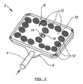
- FIG. 1 there is shown a burner head 2 of prior art configuration comprising a gas feed tube 4 which passes into a chamber 6 disposed underneath a combustion surface indicated generally by reference numeral 8. It should be pointed out that the burner heads shown in both Figures 1 and 2 are conventionally rotated through 180° about the axis of the feed tube so that the combustion surface faces downwardly and the combustion which occurs thereon provides a grilling effect on products beneath the said burner head.
- the combustion surface 8 is comprised of a punched template 10 which overlays two separate sheets of gauze arranged perpendicularly to one another to create a sufficient resistance to the flow of gas from within the chamber 6 through said sheets of gauze in the regions of apertures 12 provided in the punched template 10.
- the template 10 is provided with an indentation 14 which is spot welded at 16 to a suitable projection within the chamber 6, and this connection between these two components serves to mitigate against the effects of buckling of the template 10 as it expands while combustion is occurring on or proximate the combustion surface 8.
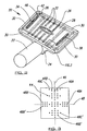
- FIG. 2 there is shown a burner 20 provided with a gas feed tube 22 entering a chamber 24 disposed underneath a combustion surface indicated generally by reference numeral 26.
- the combustion surface 26 is comprised of a single sheet 28 of stainless steel which is sealed to the chamber 24 around its periphery by means of folded edge portions 30 which are integrally formed with the chamber 24.
- Gas entering the chamber 24 through the feed tube 22 strikes a baffle (not shown) mounted at a suitable distance from the end of the feed tube 22 within the chamber 24, and is thus distributed substantially evenly within the said chamber and underneath the mettle sheet 28.
- the chamber 24 communicates directly with the perforations, indicated generally by 32, and therefore gas entering the chamber 24 is allowed to flow without obstruction or having firstly to flow through any additional component through the perforations 32.
- a number of indentations 34, 36, 38 are provided in the surface of the metal sheet 28 for the same reasons as mentioned above with regard to the indentation 14 of the burner head of Figure 1.
- the sheet 28 is provided with a further indentation 40 which protrudes outwardly from the surface of the sheet 28, and additionally with a sparking device mounting aperture 42 which is punched through both the chamber 24 and the sheet 28 approximate an edge and/or a corner thereof.
- the aperture 42 may be punched through the sheet 28 and the chamber 24 in an area where these two components have been previously sealed, for example, approximate the folded edge portions 30, and in this event a separate sealing operation after the punching operation of aperture 42 is not required.
- a suitable sparking means such as a piezo electric sparking device may thus be mounted through the aperture 42 and suitably positioned with respect to the indentation 40 which acts as a contact against which the sparking means is triggered.
- FIG 3 there is shown an enlarged portion of the surface of the metal sheet 28 which clearly demonstrates the arrangement of the perforation within the said sheet. It can be seen from Figure 3 that the pattern 44 of perforations is symmetrical about a longitudinal axis 46 and a longitudinal axis 48, both axis being described with reference to the particular direction of perforation.
- the perforations are of insufficient size to permit rapid escape of gas from within the chamber 24, but a sufficient number of perforations is provided such that a distributed and uniform flame profile can be achieved on or proximate the combustion surface 26 of the burner head 20.
- the burner of figure 2 performs equally as well as the burner of Figure 1 as regards the radiation of heat from its combustion surface 26 to and through a food product disposed beneath same. It is believed that although none of the components shown in Figure 2 glows with a visible intensity, the metal sheet 28 nevertheless radiates a sufficient amount of heat to cook products disposed beneath the said combustion surface 26.
- the surface of metal sheet 28 is provided with a plurality of defined rows 46A, 48A of perforations which intersect substantially perpendicular to one another, such as those perforations which are provided collinearly with axes 46, 48.
- rows 46B, 46C, 46B', 46C', 48B, 48B' of perforations are provided on either side of these intersecting rows 46A, 48A and parallel therewith to increase the overall perforation area in the surface of sheet 28, and also to effectively broaden the intersecting rows 46A, 48A.
- rows 46B, 46B' and 48B, 48B' are incomplete because every fourth perforation in rows 46B, 46B' and 48B, 48B' is removed, whereas only every fourth perforation is provided in rows 46C, 46C'.
- This arrangement of perforations provides a patterned effect over the surface of sheet 28, but in rows.
- the patterned effect provides a means by which burner resonance can be reduced during operation.
Abstract
Description
- The invention relates to a gas burner, and more specifically to a radiative heat gas burner of the type which are commonly incorporated in conventional gas cookers in the grills thereof.
- The type of burners to which this invention relates are also known as atmospheric burners because combustion occurs on the surface of the burner with oxygen from the ambient atmosphere fuelling the combustion, but it to be understood that the invention may have wider application, in particular to premix burners in which air is mixed with assistance from a fan to a certain extent with the combustion gas prior to combustion thereof. In the interests of brevity however, the following description relates only to atmospheric burners.
- Atmospheric burners are used to provide the grill in conventional gas cookers. One configuration of burner typically consists of a plenum chamber fabricated by pressing a steel or aluminium sheet to form a cavity with an inlet port to which a gas feed tube is brazed, welded or otherwise connected.
- A flow of combustion gas, usually methane, is introduced into the cavity from the feed tube from which it disperses within the cavity and flows substantially evenly beneath two perpendicularly disposed sheets of gauze and a punched hardened steel sheet superimposed on the gauze sheets on the surface of which combustion occurs. The hardened steel sheet is provided with a plurality of holes through which the combustion gas passes, after first having passed through the gauze sheets from the cavity, the arrangement of holes being such that a substantially uniform flame distribution is achieved over the surface of the plate. In a burner measuring 20cm by 30cm, the holes in the hardened steel sheet may be of the order of 3cm in diameter.
- The cavity is sealed both at the connection of the feed tube with the inlet port, and also around the periphery of the plate and the sheets of gauze by folding an edge of the steel pressing over the edges of the plate and sheets of gauze.
- The steel sheet is generally provided with at least one indentation to interrupt its otherwise substantially planar profile. The indentations are provided to mitigate against the buckling effects of the sheet during the expansion thereof experienced as combustion occurs on its surface. Such buckling effects result from the method by which the seal around the edge of the plate is effected in that the folding of an edge of the steel pressing around the entire periphery of the plate prevents the expansion of the said plate. To further ensure that the profile of the sheet is not substantially affected by its expansion, the sheet may be spot welded a portion of the pressing proximate the centre thereof to prevent its outward bulging during combustion which adversely affects the flame profile on the surface of said plate.
- The fundamental disadvantage of the burner construction described is one of cost. The particular components which constitute the burner are chosen to achieve a substantially uniform flame profile over the surface of the hardened steel plate, both to ensure that food products being cooked underneath the burner are not singed or burned, and to ensure that the gauze portions revealed by the holes glow with a dull, reddish colour. The glowing of the gauze portions has previously been considered essential to provide radiative heat transfer from the burner to the food and thus effective cooking thereof, the conventional disposition of the burner above the food during grilling thereof precluding convective heat transfer and the low thermal conductivity of air precluding conductive heat transfer.
- Other burner configurations have been proposed, but all configurations are directed towards the provision of radiative heat transfer from the burner to a food product being grilled underneath. For instance a "poker" type burner has been considered which comprises a cylindrical tube mounted substantially centrally of the burner from which the combustion gas flows through apertures arranged linearly along the length of the tube and on both sides thereof. Disposed above the line of apertures are provided a pair of fins angled towards each other and provided with a series of indentations over the surface. In use, combustion occurs on the lower surface of the fins with the indentations glowing and thus radiating heat downwardly onto a food product beneath the burner.
- Again, the disadvantages associated with this burner are its cost, and its complexity of construction.
- It is an object of the invention to provide a burner which is inexpensive and simple to construct and which nevertheless provides sufficient heat radiation downwardly of its surface when disposed above a food product to cook same when in use as a grill.
- According to the invention there is provided a burner head having an inlet port by which the burner is provided with a combustible gas, a chamber in which the combustion gas flows prior to combustion, and a combustion surface through which the gas passes from the chamber to combust thereon or proximate thereto, characterised in that the combustion surface is provided with a pattern of perforations, the total area of perforation as compared to the area of the combustion surface being sufficient to permit a sufficient quantity of gas to flow therethrough, and each perforation being of size which prevents any burn back within the chamber.
- The removal of the sheets of gauze from the construction of the burner has never previously been considered because of the requirement of heat radiation therefrom. The applicant has established that by simply providing a perforated combustion surface through which the combustion gas passes directly from the chamber, sufficient radiation of heat from the said combustion surface can be achieved without any requirement for portions of the combustion surface to glow.
- The combustion surface is preferably formed from a sheet of stainless steel.
- Preferably the pattern of perforations within the sheet creates a substantially uniform flame profile on or proximate the surface thereof.
- Preferably the combustion surface is provided with indentations to prevent significant buckling of the said surface during combustion thereon.
- Preferably baffle means are provided internally of the chamber to ensure substantially even distribution of the combustion gas within the chamber and underneath the combustion surface.
- Preferably the burner head is incorporated in a conventional gas cooker and provides a grill function therefor. In this particular configuration, the burner head is preferably disposed with its combustion surface facing downwardly above a tray on which food products to be cooked are placed.
- Preferably the combustion surface is provided with means for generating a spark to ignite the combustion gas.
- Preferably the sparking means is affixed through the combustion surface, an indentation being provided on said combustion surface which acts as the sparking contact against which the spark discharges.
- It is believed that the combustion surface of the burner radiates sufficient heat notwithstanding that no portion thereof glows, and it is this realisation which has given rise to the present invention.
- A specific embodiment of the invention will now be described by way of example with reference to the accompanying diagram wherein:
- Figure 1 shows a perspective view of a burner of prior art configuration,
- Figure 2 shows a perspective view of a burner according to the invention.
- Figure 3 shows an enlarged view of the pattern of the perforations provided on the combustion surface of the burner of Figure 2.
-
- Referring firstly to Figure 1 there is shown a
burner head 2 of prior art configuration comprising agas feed tube 4 which passes into achamber 6 disposed underneath a combustion surface indicated generally byreference numeral 8. It should be pointed out that the burner heads shown in both Figures 1 and 2 are conventionally rotated through 180° about the axis of the feed tube so that the combustion surface faces downwardly and the combustion which occurs thereon provides a grilling effect on products beneath the said burner head. - The
combustion surface 8 is comprised of a punchedtemplate 10 which overlays two separate sheets of gauze arranged perpendicularly to one another to create a sufficient resistance to the flow of gas from within thechamber 6 through said sheets of gauze in the regions ofapertures 12 provided in the punchedtemplate 10. - The combustion of the gas approximate or on the
combustion surface 8 heats both thetemplate 10 and the portions of the gauze sheet in the region of theapertures 12 causing them to glow with a dullish red intensity. It has heretofore been commonly believed that this glow provides sufficient radiative heat transfer from thecombustion surface 8 downwardly onto a food product disposed beneath theburner head 2 to effect cooking thereof, as opposed to merely singing or browning the surface thereof. - The
template 10 is provided with anindentation 14 which is spot welded at 16 to a suitable projection within thechamber 6, and this connection between these two components serves to mitigate against the effects of buckling of thetemplate 10 as it expands while combustion is occurring on or proximate thecombustion surface 8. - Referring now to Figure 2, there is shown a
burner 20 provided with agas feed tube 22 entering achamber 24 disposed underneath a combustion surface indicated generally byreference numeral 26. - The
combustion surface 26 is comprised of asingle sheet 28 of stainless steel which is sealed to thechamber 24 around its periphery by means of foldededge portions 30 which are integrally formed with thechamber 24. Gas entering thechamber 24 through thefeed tube 22 strikes a baffle (not shown) mounted at a suitable distance from the end of thefeed tube 22 within thechamber 24, and is thus distributed substantially evenly within the said chamber and underneath themettle sheet 28. For the avoidance of doubt, it is to be pointed out that thechamber 24 communicates directly with the perforations, indicated generally by 32, and therefore gas entering thechamber 24 is allowed to flow without obstruction or having firstly to flow through any additional component through theperforations 32. A number ofindentations metal sheet 28 for the same reasons as mentioned above with regard to theindentation 14 of the burner head of Figure 1. - The
sheet 28 is provided with a further indentation 40 which protrudes outwardly from the surface of thesheet 28, and additionally with a sparkingdevice mounting aperture 42 which is punched through both thechamber 24 and thesheet 28 approximate an edge and/or a corner thereof. Theaperture 42 may be punched through thesheet 28 and thechamber 24 in an area where these two components have been previously sealed, for example, approximate the foldededge portions 30, and in this event a separate sealing operation after the punching operation ofaperture 42 is not required. - A suitable sparking means, such as a piezo electric sparking device may thus be mounted through the
aperture 42 and suitably positioned with respect to the indentation 40 which acts as a contact against which the sparking means is triggered. - Referring finally to Figure 3, there is shown an enlarged portion of the surface of the
metal sheet 28 which clearly demonstrates the arrangement of the perforation within the said sheet. It can be seen from Figure 3 that thepattern 44 of perforations is symmetrical about alongitudinal axis 46 and alongitudinal axis 48, both axis being described with reference to the particular direction of perforation. - It will be understood from the foregoing, and particularly with reference to Figure 3, that individually, the perforations are of insufficient size to permit rapid escape of gas from within the
chamber 24, but a sufficient number of perforations is provided such that a distributed and uniform flame profile can be achieved on or proximate thecombustion surface 26 of theburner head 20. Furthermore, it has been shown in experiments that the burner of figure 2 performs equally as well as the burner of Figure 1 as regards the radiation of heat from itscombustion surface 26 to and through a food product disposed beneath same. It is believed that although none of the components shown in Figure 2 glows with a visible intensity, themetal sheet 28 nevertheless radiates a sufficient amount of heat to cook products disposed beneath the saidcombustion surface 26. - As can be seen from Figure 3, it is a preferable feature of the invention that the surface of
metal sheet 28 is provided with a plurality ofdefined rows axes incomplete rows rows sheet 28, and also to effectively broaden the intersectingrows rows rows sheet 28, but in rows. - The patterned effect provides a means by which burner resonance can be reduced during operation.
Claims (9)
- A radiative heat burner head having an inlet port by which the burner is provided with a combustible gas, a chamber in which the combustion gas flows prior to combustion, and a combustion surface through which the gas passes from the chamber to combust thereon or proximate thereto, characterised in that the combustion surface is provided with a pattern of perforations, the total area of perforation as compared to the area of the combustion surface being sufficient to permit a sufficient quantity of gas to flow therethrough, and each perforation being of size which prevents any burn back within the chamber.
- A burner according to claim 1 characterised in that the combustion surface is formed from a sheet of stainless steel.
- A burner according to claim 2 characterised in that the pattern of perforations within the sheet creates a substantially uniform flame profile on or proximate the surface thereof.
- A burner according to any of the preceding claims characterised in that the combustion surface is provided with indentations to prevent significant buckling of the said surface during combustion thereon or proximate thereto.
- A burner according to any of the preceding claims characterised in that baffle means are provided internally of the chamber to ensure substantially even distribution of the combustion gas within the chamber and behind the combustion surface.
- A burner according to any of the preceding claims characterised in that the burner head is incorporated in a conventional gas cooker and provides a grill function therefor.
- A burner according claim 6 characterised in that the burner head is disposed with its combustion surface facing downwardly above a grill tray on which food products to be cooked may be placed.
- A burner according to any of the preceding claims characterised in that the combustion surface is provided with means for generating a spark to ignite the combustion gas.
- A burner according to claim 8 characterised in that the sparking means is affixed through the combustion surface, an indentation being further provided on said combustion surface which acts as the sparking contact against which the spark discharges.
Applications Claiming Priority (2)
| Application Number | Priority Date | Filing Date | Title |
|---|---|---|---|
| GB9827620 | 1998-12-16 | ||
| GBGB9827620.7A GB9827620D0 (en) | 1998-12-16 | 1998-12-16 | Gas burner |
Publications (3)
| Publication Number | Publication Date |
|---|---|
| EP1010940A2 true EP1010940A2 (en) | 2000-06-21 |
| EP1010940A3 EP1010940A3 (en) | 2001-03-07 |
| EP1010940B1 EP1010940B1 (en) | 2004-07-07 |
Family
ID=10844274
Family Applications (1)
| Application Number | Title | Priority Date | Filing Date |
|---|---|---|---|
| EP99122916A Expired - Lifetime EP1010940B1 (en) | 1998-12-16 | 1999-11-18 | Gas Burner |
Country Status (5)
| Country | Link |
|---|---|
| US (1) | US20010036610A1 (en) |
| EP (1) | EP1010940B1 (en) |
| AT (1) | ATE270760T1 (en) |
| DE (1) | DE69918517D1 (en) |
| GB (1) | GB9827620D0 (en) |
Cited By (1)
| Publication number | Priority date | Publication date | Assignee | Title |
|---|---|---|---|---|
| US6843649B2 (en) | 2002-05-25 | 2005-01-18 | Bray Burners Limited | Burner |
Families Citing this family (14)
| Publication number | Priority date | Publication date | Assignee | Title |
|---|---|---|---|---|
| JP3687098B2 (en) * | 2002-12-11 | 2005-08-24 | 株式会社ノーリツ | Combustion tube and gas combustion apparatus equipped with the combustion tube |
| US7853129B2 (en) * | 2004-06-23 | 2010-12-14 | Char-Broil, Llc | Infrared emitting apparatus |
| WO2008039463A1 (en) * | 2006-09-26 | 2008-04-03 | Best Willie H | Cooking apparatus with concave emitter |
| DK2363645T3 (en) * | 2006-11-10 | 2017-10-23 | Char-Broil Llc | Oven with radiant tube |
| EP2384135B1 (en) * | 2008-12-01 | 2013-08-14 | Char-Broil, LLC | Methods and apparatus for generating infrared radiation from convective products of combustion |
| US8776775B2 (en) * | 2009-06-29 | 2014-07-15 | W.C. Bradley Co. | Single cavity radiant cooking apparatus |
| TWI570362B (en) | 2010-12-20 | 2017-02-11 | 索拉羅尼克斯股份有限公司 | Gas fired radiation emitter with embossed screen |
| CN104994741B (en) | 2012-11-15 | 2021-04-13 | W.C.布拉德利公司 | Electric oven and fumigator |
| GB2509492A (en) * | 2012-12-19 | 2014-07-09 | Worgas Burners Ltd | A gas burner having a combustion surface formed by a sheet with plural apertures |
| US9668613B2 (en) | 2013-06-17 | 2017-06-06 | W.C. Bradley Co. | High efficiency apparatus and method for cooking, heating and drying |
| CN105451567B (en) | 2013-06-17 | 2021-08-03 | W.C.布拉德利公司 | Outdoor cooker and smoker and fuel burner therefor |
| US9709281B2 (en) | 2014-03-31 | 2017-07-18 | W.C. Bradley Co. | High efficiency side burner and outdoor cooker |
| WO2016154114A1 (en) | 2015-03-25 | 2016-09-29 | W.C. Bradley Co. | Vertical electric cooker and smoker and smoke box |
| US10088153B2 (en) * | 2015-12-29 | 2018-10-02 | Clearsign Combustion Corporation | Radiant wall burner including perforated flame holders |
Citations (6)
| Publication number | Priority date | Publication date | Assignee | Title |
|---|---|---|---|---|
| FR1387132A (en) * | 1962-12-11 | 1965-01-29 | Hupp Corp | Improvement in infrared radiation heating |
| FR1449685A (en) * | 1965-05-07 | 1966-05-06 | radiant element for gas burner | |
| US4752213A (en) * | 1985-11-06 | 1988-06-21 | Gaz De France | Forced-air gas burner |
| EP0415008A1 (en) * | 1989-08-12 | 1991-03-06 | Klöckner Wärmetechnik Gmbh Zweigniederlassung Hechingen | Method of combustion in gasburner |
| US5046944A (en) * | 1979-11-16 | 1991-09-10 | Smith Thomas M | Infra-red generation |
| US5060629A (en) * | 1989-02-07 | 1991-10-29 | Centre D'etude Et De Realisation D'equipements Et De Materiel (C.E.R.E.M.) | Heating apparatus of the infrared type |
-
1998
- 1998-12-16 GB GBGB9827620.7A patent/GB9827620D0/en not_active Ceased
-
1999
- 1999-11-18 AT AT99122916T patent/ATE270760T1/en not_active IP Right Cessation
- 1999-11-18 EP EP99122916A patent/EP1010940B1/en not_active Expired - Lifetime
- 1999-11-18 DE DE69918517T patent/DE69918517D1/en not_active Expired - Lifetime
-
2001
- 2001-06-14 US US09/883,063 patent/US20010036610A1/en not_active Abandoned
Patent Citations (6)
| Publication number | Priority date | Publication date | Assignee | Title |
|---|---|---|---|---|
| FR1387132A (en) * | 1962-12-11 | 1965-01-29 | Hupp Corp | Improvement in infrared radiation heating |
| FR1449685A (en) * | 1965-05-07 | 1966-05-06 | radiant element for gas burner | |
| US5046944A (en) * | 1979-11-16 | 1991-09-10 | Smith Thomas M | Infra-red generation |
| US4752213A (en) * | 1985-11-06 | 1988-06-21 | Gaz De France | Forced-air gas burner |
| US5060629A (en) * | 1989-02-07 | 1991-10-29 | Centre D'etude Et De Realisation D'equipements Et De Materiel (C.E.R.E.M.) | Heating apparatus of the infrared type |
| EP0415008A1 (en) * | 1989-08-12 | 1991-03-06 | Klöckner Wärmetechnik Gmbh Zweigniederlassung Hechingen | Method of combustion in gasburner |
Cited By (1)
| Publication number | Priority date | Publication date | Assignee | Title |
|---|---|---|---|---|
| US6843649B2 (en) | 2002-05-25 | 2005-01-18 | Bray Burners Limited | Burner |
Also Published As
| Publication number | Publication date |
|---|---|
| US20010036610A1 (en) | 2001-11-01 |
| EP1010940A3 (en) | 2001-03-07 |
| ATE270760T1 (en) | 2004-07-15 |
| DE69918517D1 (en) | 2004-08-12 |
| EP1010940B1 (en) | 2004-07-07 |
| GB9827620D0 (en) | 1999-02-10 |
Similar Documents
| Publication | Publication Date | Title |
|---|---|---|
| EP1010940B1 (en) | Gas Burner | |
| EP1776028B1 (en) | Infrared emitting apparatus | |
| CA2336036C (en) | Heating assembly and cooking apparatus | |
| EP2091396B1 (en) | Cooking apparatus with concave emitter | |
| US5755154A (en) | Gas barbecue assembly | |
| US6267047B1 (en) | Portable griddle stove with dual cooking surfaces | |
| US5740723A (en) | Portable outdoor high temperature griddle | |
| WO1996028075A1 (en) | Barbecue grill with fluidic burner and heat distribution system | |
| GB2299748A (en) | Apparatus for barbecue grilling of food | |
| JP4312756B2 (en) | Smokeless pottery | |
| JP2010203632A (en) | Burner cover and heating cooker using the same | |
| US20040033461A1 (en) | Burner | |
| CN220442509U (en) | Cooking device with high temperature area | |
| CN218599787U (en) | Pizza oven | |
| KR100363598B1 (en) | heating apparatus of gas griddle | |
| KR101860673B1 (en) | Roasting grill apparatus | |
| CA2354503A1 (en) | Grill equipped with a ceran glass cooking device | |
| JP2612826B2 (en) | Gas burner | |
| JPH01269814A (en) | Burner | |
| KR960009702Y1 (en) | Gas burner | |
| JP2649496B2 (en) | Infrared burner | |
| JPH0217328A (en) | Broiling device | |
| JPH0710687Y2 (en) | Grill device | |
| JP2023100524A (en) | heating cooker | |
| JP2588824B2 (en) | Firing equipment |
Legal Events
| Date | Code | Title | Description |
|---|---|---|---|
| PUAI | Public reference made under article 153(3) epc to a published international application that has entered the european phase |
Free format text: ORIGINAL CODE: 0009012 |
|
| AK | Designated contracting states |
Kind code of ref document: A2 Designated state(s): AT BE CH CY DE DK ES FI FR GB GR IE IT LI LU MC NL PT SE |
|
| AX | Request for extension of the european patent |
Free format text: AL;LT;LV;MK;RO;SI |
|
| PUAL | Search report despatched |
Free format text: ORIGINAL CODE: 0009013 |
|
| AK | Designated contracting states |
Kind code of ref document: A3 Designated state(s): AT BE CH CY DE DK ES FI FR GB GR IE IT LI LU MC NL PT SE |
|
| AX | Request for extension of the european patent |
Free format text: AL;LT;LV;MK;RO;SI |
|
| 17P | Request for examination filed |
Effective date: 20010830 |
|
| AKX | Designation fees paid |
Free format text: AT BE CH CY DE DK ES FI FR GB GR IE IT LI LU MC NL PT SE |
|
| 17Q | First examination report despatched |
Effective date: 20030702 |
|
| GRAP | Despatch of communication of intention to grant a patent |
Free format text: ORIGINAL CODE: EPIDOSNIGR1 |
|
| GRAS | Grant fee paid |
Free format text: ORIGINAL CODE: EPIDOSNIGR3 |
|
| GRAA | (expected) grant |
Free format text: ORIGINAL CODE: 0009210 |
|
| RAP1 | Party data changed (applicant data changed or rights of an application transferred) |
Owner name: SIT-BRAY LIMITED |
|
| AK | Designated contracting states |
Kind code of ref document: B1 Designated state(s): AT BE CH CY DE DK ES FI FR GB GR IE IT LI LU MC NL PT SE |
|
| PG25 | Lapsed in a contracting state [announced via postgrant information from national office to epo] |
Ref country code: NL Free format text: LAPSE BECAUSE OF FAILURE TO SUBMIT A TRANSLATION OF THE DESCRIPTION OR TO PAY THE FEE WITHIN THE PRESCRIBED TIME-LIMIT Effective date: 20040707 Ref country code: LI Free format text: LAPSE BECAUSE OF FAILURE TO SUBMIT A TRANSLATION OF THE DESCRIPTION OR TO PAY THE FEE WITHIN THE PRESCRIBED TIME-LIMIT Effective date: 20040707 Ref country code: FR Free format text: LAPSE BECAUSE OF FAILURE TO SUBMIT A TRANSLATION OF THE DESCRIPTION OR TO PAY THE FEE WITHIN THE PRESCRIBED TIME-LIMIT Effective date: 20040707 Ref country code: FI Free format text: LAPSE BECAUSE OF FAILURE TO SUBMIT A TRANSLATION OF THE DESCRIPTION OR TO PAY THE FEE WITHIN THE PRESCRIBED TIME-LIMIT Effective date: 20040707 Ref country code: ES Free format text: LAPSE BECAUSE OF FAILURE TO SUBMIT A TRANSLATION OF THE DESCRIPTION OR TO PAY THE FEE WITHIN THE PRESCRIBED TIME-LIMIT Effective date: 20040707 Ref country code: CY Free format text: LAPSE BECAUSE OF FAILURE TO SUBMIT A TRANSLATION OF THE DESCRIPTION OR TO PAY THE FEE WITHIN THE PRESCRIBED TIME-LIMIT Effective date: 20040707 Ref country code: CH Free format text: LAPSE BECAUSE OF FAILURE TO SUBMIT A TRANSLATION OF THE DESCRIPTION OR TO PAY THE FEE WITHIN THE PRESCRIBED TIME-LIMIT Effective date: 20040707 Ref country code: BE Free format text: LAPSE BECAUSE OF FAILURE TO SUBMIT A TRANSLATION OF THE DESCRIPTION OR TO PAY THE FEE WITHIN THE PRESCRIBED TIME-LIMIT Effective date: 20040707 Ref country code: AT Free format text: LAPSE BECAUSE OF FAILURE TO SUBMIT A TRANSLATION OF THE DESCRIPTION OR TO PAY THE FEE WITHIN THE PRESCRIBED TIME-LIMIT Effective date: 20040707 |
|
| REG | Reference to a national code |
Ref country code: GB Ref legal event code: FG4D |
|
| REG | Reference to a national code |
Ref country code: CH Ref legal event code: EP |
|
| REG | Reference to a national code |
Ref country code: IE Ref legal event code: FG4D |
|
| REF | Corresponds to: |
Ref document number: 69918517 Country of ref document: DE Date of ref document: 20040812 Kind code of ref document: P |
|
| PG25 | Lapsed in a contracting state [announced via postgrant information from national office to epo] |
Ref country code: SE Free format text: LAPSE BECAUSE OF FAILURE TO SUBMIT A TRANSLATION OF THE DESCRIPTION OR TO PAY THE FEE WITHIN THE PRESCRIBED TIME-LIMIT Effective date: 20041007 Ref country code: GR Free format text: LAPSE BECAUSE OF FAILURE TO SUBMIT A TRANSLATION OF THE DESCRIPTION OR TO PAY THE FEE WITHIN THE PRESCRIBED TIME-LIMIT Effective date: 20041007 Ref country code: DK Free format text: LAPSE BECAUSE OF FAILURE TO SUBMIT A TRANSLATION OF THE DESCRIPTION OR TO PAY THE FEE WITHIN THE PRESCRIBED TIME-LIMIT Effective date: 20041007 |
|
| PG25 | Lapsed in a contracting state [announced via postgrant information from national office to epo] |
Ref country code: DE Free format text: LAPSE BECAUSE OF FAILURE TO SUBMIT A TRANSLATION OF THE DESCRIPTION OR TO PAY THE FEE WITHIN THE PRESCRIBED TIME-LIMIT Effective date: 20041008 |
|
| PG25 | Lapsed in a contracting state [announced via postgrant information from national office to epo] |
Ref country code: LU Free format text: LAPSE BECAUSE OF NON-PAYMENT OF DUE FEES Effective date: 20041118 Ref country code: IE Free format text: LAPSE BECAUSE OF NON-PAYMENT OF DUE FEES Effective date: 20041118 |
|
| PG25 | Lapsed in a contracting state [announced via postgrant information from national office to epo] |
Ref country code: MC Free format text: LAPSE BECAUSE OF NON-PAYMENT OF DUE FEES Effective date: 20041130 |
|
| NLV1 | Nl: lapsed or annulled due to failure to fulfill the requirements of art. 29p and 29m of the patents act | ||
| REG | Reference to a national code |
Ref country code: CH Ref legal event code: PL |
|
| PLBE | No opposition filed within time limit |
Free format text: ORIGINAL CODE: 0009261 |
|
| STAA | Information on the status of an ep patent application or granted ep patent |
Free format text: STATUS: NO OPPOSITION FILED WITHIN TIME LIMIT |
|
| 26N | No opposition filed |
Effective date: 20050408 |
|
| EN | Fr: translation not filed | ||
| REG | Reference to a national code |
Ref country code: IE Ref legal event code: MM4A |
|
| PG25 | Lapsed in a contracting state [announced via postgrant information from national office to epo] |
Ref country code: PT Free format text: LAPSE BECAUSE OF NON-PAYMENT OF DUE FEES Effective date: 20041207 |
|
| PGFP | Annual fee paid to national office [announced via postgrant information from national office to epo] |
Ref country code: GB Payment date: 20181029 Year of fee payment: 20 Ref country code: IT Payment date: 20181026 Year of fee payment: 20 |
|
| REG | Reference to a national code |
Ref country code: GB Ref legal event code: PE20 Expiry date: 20191117 |
|
| PG25 | Lapsed in a contracting state [announced via postgrant information from national office to epo] |
Ref country code: GB Free format text: LAPSE BECAUSE OF EXPIRATION OF PROTECTION Effective date: 20191117 |