EP1010803A2 - Device for detecting the end of service life for synthetic fibre ropes - Google Patents
Device for detecting the end of service life for synthetic fibre ropes Download PDFInfo
- Publication number
- EP1010803A2 EP1010803A2 EP99123810A EP99123810A EP1010803A2 EP 1010803 A2 EP1010803 A2 EP 1010803A2 EP 99123810 A EP99123810 A EP 99123810A EP 99123810 A EP99123810 A EP 99123810A EP 1010803 A2 EP1010803 A2 EP 1010803A2
- Authority
- EP
- European Patent Office
- Prior art keywords
- rope
- strands
- strand
- stranded
- recognizing
- Prior art date
- Legal status (The legal status is an assumption and is not a legal conclusion. Google has not performed a legal analysis and makes no representation as to the accuracy of the status listed.)
- Granted
Links
- 229920002994 synthetic fiber Polymers 0.000 title claims abstract description 9
- 229920006231 aramid fiber Polymers 0.000 claims abstract description 15
- 239000012209 synthetic fiber Substances 0.000 claims abstract description 8
- 238000001514 detection method Methods 0.000 claims description 5
- 230000001419 dependent effect Effects 0.000 claims 1
- 239000000835 fiber Substances 0.000 abstract description 3
- 230000003313 weakening effect Effects 0.000 abstract description 3
- 229920002635 polyurethane Polymers 0.000 description 5
- 239000004814 polyurethane Substances 0.000 description 5
- 239000004760 aramid Substances 0.000 description 4
- 239000000463 material Substances 0.000 description 4
- 229920003235 aromatic polyamide Polymers 0.000 description 3
- 238000006073 displacement reaction Methods 0.000 description 3
- 238000005299 abrasion Methods 0.000 description 2
- 230000007935 neutral effect Effects 0.000 description 2
- 230000000007 visual effect Effects 0.000 description 2
- 239000000853 adhesive Substances 0.000 description 1
- 230000001070 adhesive effect Effects 0.000 description 1
- 238000005452 bending Methods 0.000 description 1
- 230000005540 biological transmission Effects 0.000 description 1
- 239000003795 chemical substances by application Substances 0.000 description 1
- 238000010276 construction Methods 0.000 description 1
- 230000000694 effects Effects 0.000 description 1
- 230000009969 flowable effect Effects 0.000 description 1
- 239000003550 marker Substances 0.000 description 1
- 238000000034 method Methods 0.000 description 1
- 239000003973 paint Substances 0.000 description 1
- 239000004033 plastic Substances 0.000 description 1
- 229920003023 plastic Polymers 0.000 description 1
- 229920000728 polyester Polymers 0.000 description 1
- 230000002028 premature Effects 0.000 description 1
- 230000001681 protective effect Effects 0.000 description 1
- 238000005507 spraying Methods 0.000 description 1
- 238000011179 visual inspection Methods 0.000 description 1
Images
Classifications
-
- D—TEXTILES; PAPER
- D07—ROPES; CABLES OTHER THAN ELECTRIC
- D07B—ROPES OR CABLES IN GENERAL
- D07B1/00—Constructional features of ropes or cables
- D07B1/14—Ropes or cables with incorporated auxiliary elements, e.g. for marking, extending throughout the length of the rope or cable
-
- D—TEXTILES; PAPER
- D07—ROPES; CABLES OTHER THAN ELECTRIC
- D07B—ROPES OR CABLES IN GENERAL
- D07B1/00—Constructional features of ropes or cables
- D07B1/02—Ropes built-up from fibrous or filamentary material, e.g. of vegetable origin, of animal origin, regenerated cellulose, plastics
-
- D—TEXTILES; PAPER
- D07—ROPES; CABLES OTHER THAN ELECTRIC
- D07B—ROPES OR CABLES IN GENERAL
- D07B1/00—Constructional features of ropes or cables
- D07B1/14—Ropes or cables with incorporated auxiliary elements, e.g. for marking, extending throughout the length of the rope or cable
- D07B1/145—Ropes or cables with incorporated auxiliary elements, e.g. for marking, extending throughout the length of the rope or cable comprising elements for indicating or detecting the rope or cable status
-
- D—TEXTILES; PAPER
- D07—ROPES; CABLES OTHER THAN ELECTRIC
- D07B—ROPES OR CABLES IN GENERAL
- D07B1/00—Constructional features of ropes or cables
- D07B1/14—Ropes or cables with incorporated auxiliary elements, e.g. for marking, extending throughout the length of the rope or cable
- D07B1/148—Ropes or cables with incorporated auxiliary elements, e.g. for marking, extending throughout the length of the rope or cable comprising marks or luminous elements
-
- D—TEXTILES; PAPER
- D07—ROPES; CABLES OTHER THAN ELECTRIC
- D07B—ROPES OR CABLES IN GENERAL
- D07B1/00—Constructional features of ropes or cables
- D07B1/02—Ropes built-up from fibrous or filamentary material, e.g. of vegetable origin, of animal origin, regenerated cellulose, plastics
- D07B1/025—Ropes built-up from fibrous or filamentary material, e.g. of vegetable origin, of animal origin, regenerated cellulose, plastics comprising high modulus, or high tenacity, polymer filaments or fibres, e.g. liquid-crystal polymers
-
- D—TEXTILES; PAPER
- D07—ROPES; CABLES OTHER THAN ELECTRIC
- D07B—ROPES OR CABLES IN GENERAL
- D07B2201/00—Ropes or cables
- D07B2201/10—Rope or cable structures
- D07B2201/1012—Rope or cable structures characterised by their internal structure
- D07B2201/1016—Rope or cable structures characterised by their internal structure characterised by the use of different strands
-
- D—TEXTILES; PAPER
- D07—ROPES; CABLES OTHER THAN ELECTRIC
- D07B—ROPES OR CABLES IN GENERAL
- D07B2201/00—Ropes or cables
- D07B2201/10—Rope or cable structures
- D07B2201/1028—Rope or cable structures characterised by the number of strands
- D07B2201/1036—Rope or cable structures characterised by the number of strands nine or more strands respectively forming multiple layers
-
- D—TEXTILES; PAPER
- D07—ROPES; CABLES OTHER THAN ELECTRIC
- D07B—ROPES OR CABLES IN GENERAL
- D07B2201/00—Ropes or cables
- D07B2201/10—Rope or cable structures
- D07B2201/104—Rope or cable structures twisted
- D07B2201/1076—Open winding
- D07B2201/108—Cylinder winding, i.e. S/Z or Z/S
-
- D—TEXTILES; PAPER
- D07—ROPES; CABLES OTHER THAN ELECTRIC
- D07B—ROPES OR CABLES IN GENERAL
- D07B2201/00—Ropes or cables
- D07B2201/20—Rope or cable components
- D07B2201/2071—Spacers
- D07B2201/2074—Spacers in radial direction
-
- D—TEXTILES; PAPER
- D07—ROPES; CABLES OTHER THAN ELECTRIC
- D07B—ROPES OR CABLES IN GENERAL
- D07B2205/00—Rope or cable materials
- D07B2205/20—Organic high polymers
- D07B2205/2046—Polyamides, e.g. nylons
- D07B2205/205—Aramides
-
- D—TEXTILES; PAPER
- D07—ROPES; CABLES OTHER THAN ELECTRIC
- D07B—ROPES OR CABLES IN GENERAL
- D07B2401/00—Aspects related to the problem to be solved or advantage
- D07B2401/20—Aspects related to the problem to be solved or advantage related to ropes or cables
- D07B2401/2015—Killing or avoiding twist
Definitions
- the invention relates to a device for Discarding maturity detection of synthetic fiber ropes, preferably from aromatic polyamide, according to the preamble of claim 1.
- the Strand rope consists of several layers with each other stranded high-strength synthetic fibers made by a firmly adhering Rope sheath are surrounded.
- the rope sheath shows abrasive wear as a result of driving or driven ropes due to differences in force the slip caused by the traction sheave.
- the abrasive wear of the sheath is due to the defined running surface of the ropes in the traction sheave, based on empirical values for Relative state of wear inside the ropes. Accordingly, as soon as the underlying color is visible, on the maximum permissible internal rope wear closed and the rope is within a predetermined Time to replace.
- the invention is based on the problem of a device for Detection of the maturity of ropes to show which the actual wear condition is reliably displayed.
- the essence of the invention consists in an outward rotation-neutral rope construction, in which between the individual strand layers a reactive torque ratio ensures that the rope is an unstable Takes equilibrium position.
- the ratio of mutually rotating moments of the rope is designed that weakening of strands by abrasive Wear or other influences on the inside Torque balance disturbs, so that the worn out Rope turns under load during operation around its longitudinal axis, until there is a change in torque ratios corresponding new equilibrium.
- the turning of the So rope is a sign that the rope is inside Has wear, through which a change in rope-specific properties, e.g. a loss of Breaking strength, has occurred. Accordingly, the Rope structure change using a suitable device recorded and from there on the reaching of the rope's maturity closed, even simple rope deformations Are signs of inadmissible rope wear.
- any Form of wear of the rope is very easy to use a twist of the rope can be detected as soon as the weakening of the load-bearing rope structure due to wear determinable extent exceeds. Turning the rope and thus the discard can be done without expensive additional Facilities are found.
- a friction-reducing intermediate sheath is formed between the neighboring counter-stranded concentric Strand layers. It has the advantage that the choice of materials and the Dimensioning of the intermediate jacket the radial distance of the Strand layers chosen to each other and thus that Torque balance can be adjusted. Also can a desired over the durability of the intermediate sheath Lifespan of the rope.
- a preferred embodiment of the invention is at the outermost strand layer with a multi-layer strand rope with counterstrike on a parallel stranded multilayer Inside of rope wrapped. It offers the advantage that the to the outermost strand layer bordering rope layer of the one carrying it Rope interior is exposed to maximum transverse stress and consequently, the filaments or strands of this strand layer all other damaged areas. This will only make this selected strand layer weakened, while all others Strand layers remain intact and sufficient Ensure the remaining load-bearing capacity of the synthetic fiber rope.
- the twisting of the rope is in preferred training by means of one on the outer surface of the wear-free Marking applied in the longitudinal direction of the rope indicated by the marking helically around the longitudinal axis of the rope winds.
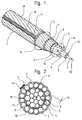
- Figure 1 shows a sheathed aramid fiber rope 1 in three concentric layers of tensile strength stranded together or load-bearing aramid fiber strands 2,3,4,5, like it is used, for example, as a driving rope in elevator systems.
- the aramid fiber rope 1 is essentially composed of one parallel stranded rope core 6 around the invention a top layer 7 is stranded in the counter-lay. Between the Cover layer 7 and the adjacent strand layer 8 of the rope core 6 there is an intermediate jacket 9, preferably made of Polyurethane. Outside, a cable sheath 10 envelops the top layer 7, which is firmly attached to it.
- an abrasion-resistant paint line 11 for Marking of the rotational position of the aramid fiber rope applied instead of the color line 11, other devices can be provided, which are suitable the rotational position of the Aramid fiber rope 1 to recognize its longitudinal axis 20 and / or to investigate.
- Top layer 7 in cooperation with the top layer 7 bordering strand layer 8 of the rope core 6 and the intermediate sheath 9 and the color line 11 together the inventive Device for detecting the maturity of the aramid fiber rope 1.
- the rope core 6 is constructed from a core strand 2, around which in a first beat direction 12, for example, five of the same Strands 3 of a first strand layer 13 helically are laid with which another ten strands 3, 4 one second strand layer 14 in parallel lay under one balanced ratio between fiber and strand twist are stranded.
- the second strand layer 14 consists of one alternating arrangement of two types of five each same strands 3.4 together.
- a further five strands 4 are present with the rope cross section larger diameter helical in the valleys of the they carry first strand layer 13, while five strands 3 with Diameter of the strands 3 of the first strand layer 13 on the The crests of the first strand layer 13 carrying them lie and thereby the gaps between two neighboring ones Fill in larger-diameter strands 4. That way gets the rope core 6, twisted in parallel, a second Strand layer 8 with an almost circular outer contour that continues advantages described below in cooperation with the Intermediate jacket 9 offers.
- the parallel stranding builds under the longitudinal load of the rope 1 of the rope core 6 opposite to the direction of lay 12 directed torque.
- the top layer 7 here consists of seventeen also load-bearing Aramid fiber strands 5 which are in the first lay direction 12 opposite twisted lay direction 15 are stranded. she builds a torque under longitudinal load of the rope 1, the to that of the parallel stranded rope core 6 is directed in the opposite direction.
- a balanced aramid fiber rope 1 behaves like this Load is neutral when running over a traction sheave.
- multiple stranded Stranded layers are formed. With regard to with the Invention achieved advantageous effect, care must be taken that a certain torque ratio of the strand layers is not less than 0.1 to 1.
- the radial distance between the strand layers mutually decisive factor is determined by the diameter of the strands used, the thickness of the the intermediate sheath described below, the number of Strand layers in the rope core and the number of strands used in the top layer. The latter can, for example, together with non-load-bearing strands should be stranded to the top layer.
- All of the supporting strands used for the aramid fiber rope 1 2,3,4,5 are twisted from individual aramid fibers or beaten and with a protective aramid fiber Impregnating agent, for example with polyurethane solution, treated.
- High-strength synthetic fibers such as aromatic polyamides or aramids with highly oriented Molecular chains have a high load capacity and a low one specific weight. They show because of their atomic However, they have a low elongation at break and are sensitive against occurring transverse loads.
- This one Material properties are used according to the invention in order to the state of wear of a rope in a simple manner high-strength fibers inside the rope through a visual display ascertain.
- the intermediate sheath 9 between the rope core 6 and the cover layer 7 consists of polyurethane or polyester. He is in Pressure spraying process applied to the core 6 and fills all spaces 17, 18 between the strands 3, 4, 5 of the two adjacent strand layers 7.14. This creates an impression Form fit with a large holding surface that leads to the inner Torque transmission between rope core 8 and cover layer 11 is used.
- the intermediate jacket 9 prevents contact between the Cover layer 7 and the second strand layer 14 and thus wear the strands 3, 4 and 5 by rubbing against each other when Run of the rope 1 over a traction sheave, not shown here and the resulting relative movement of the strands 2, 3, 4, 5 among themselves.
- the thickness of the intermediate jacket 9 is so dimensioned that with a maximum permissible rope load under which lacing force generated by the cover layer 7 creates the spaces between the strands 17, 18 are completely filled and a residual jacket thickness 16 of 0.1 mm between strands 3.4 and 5 of the neighboring ones Strand layers 14 and 7 is ensured.
- the rope sheath 10 made of polyurethane envelops the top layer 7 and ensures the desired coefficient of friction with the traction sheave.
- the Polyurethane is so resistant to abrasion that when the rope runs 1 over the traction sheave no damage.
- the rope sheath 10 is continuously extruded onto the top layer 7, which flowable plastic material in all gaps 17, 18 of the cover strand layer 7 is pressed and thus a large one Forms adhesive surface.
- On the outer surface 19 of the Rope sheath 10 is a in the longitudinal direction of the rope 1 running color line 11 applied as Reference mark indicates the rotational position of the rope 1 in. Instead of the color line 11, other devices can be used or marking are provided, which are in a suitable form Turn rope 1 to make it recognizable.
- the color line 11 or the corresponding facility can also directly on the Cover layer 7 may be applied if no cable sheath 10 is provided.
- Subsequent functioning of the so far described Device for the detection of maturity of synthetic fiber ropes refers to a powered elevator rope Aramid fibers, which is a cabin frame one in one Elevator shaft guided cabin with a counterweight connects. To lift and close the cabin and counterweight lower, the rope runs over a traction sheave by one Drive motor is driven. The drive torque is below The frictional connection via the wrap angle adjacent rope section stamped. The rope is 1 exposed to high transverse stress.
- the neutral rope 1 according to the invention is without a twist, i.e. without it between the non-rotatable attachment points on the one hand on the cabin and the counterweight on the other its longitudinal axis 20 is twisted, placed over the traction sheave.
- this serves as a color line 11 trained marking in the longitudinal direction of the rope 1 at the same time as an assembly aid for aligning the rotational position of the Seils 1 relative to a reference point, e.g. to the traction sheave.
- the rope 1 is expediently provided with such a Orientation that the course of the marker at running rope 1 can be checked visually.
- the turning of the rope 1 can be recognized visually by the fact that the color line 11 or a corresponding, other Marking in the longitudinal direction of the rope 1, around itself helically the longitudinal axis 20 of the rope 1 winds. Even simple ones Rope deformations are already a sign that the one above called mechanism is present.
Landscapes
- Ropes Or Cables (AREA)
- Lift-Guide Devices, And Elevator Ropes And Cables (AREA)
- Treatment Of Fiber Materials (AREA)
- Insulated Conductors (AREA)
- A Measuring Device Byusing Mechanical Method (AREA)
- Emergency Lowering Means (AREA)
Abstract
Zur Erkennung der Ablegereife von geschlagenen Kunstfaserseilen
(1), vorzugsweise Aramidfaserseilen, ist durch mindestens zwei
im Gegenschlag miteinander verseilte Litzenlagen (7,14) ein
drehneutraler Seilaufbau aus tragenden Faserlitzen (2,3,4,5)
vorgesehen, indem sich die verseilungsbedingten Drehmomente der
Litzenlagen (7,14) gegenseitig ausgleichen. Bei durch
Verschleiss oder Fremdeinwirkung bedingten ungleichen
Schwächungen der Litzenlagen (7,14) fängt das Seil (1) unter
Last im laufenden Betrieb an sich um seine Längsachse (20) zu
drehen. Das Drehen des Seils (1) kann mittels verschiederer
Massnahmen sichtbar gemacht werden. Bei einer Ausführungsart
dient eine in Seillängsrichtung vorgesehene Markierung (11) zur
visuellen Erkennung der Ablegereife anhand der Seildrehung.

Description
Die Erfindung betrifft eine Einrichtung zur
Ablegereifeerkennung von Kunstfaserseilen, vorzugsweise aus
aromatischem Polyamid, nach dem Oberbegriff des Anspruchs 1.The invention relates to a device for
Discarding maturity detection of synthetic fiber ropes, preferably from
aromatic polyamide, according to the preamble of
Aus der EP 0 731 209 A1 ist eine solche Einrichtung zur Erkennung der Ablegereife eines Litzenseils bekannt. Das Litzenseil besteht aus in mehreren Lagen miteinander verseilten hochfesten Kunstfasern, die von einem festhaftenden Seilmantel umgeben sind. Zur Erkennung des maximal zulässigen inneren Seilverschleisses, ist der extrudierte Mantel des Seiles koaxial farblich unterteilt. Der Seilmantel zeigt abrasiven Verschleiss in Folge des bei treibenden beziehungsweise getriebenen Seilen durch Kraftdifferenzen auf der Treibscheibe bedingten Schlupfs. Der abrasive Verschleiss des Mantels wird aufgrund der definierten Lauffläche der Seile in der Treibscheibe, anhand von Erfahrungswerten zum Verschleisszustand im Innern der Seile in Relation gesetzt. Dementsprechend wird sobald die unterhalb liegende Farbe sichtbar ist, auf maximal zulässigen inneren Seilverschleiss geschlossen und das Seil ist innerhalb einer vorgegebenen Verbleibzeit zu ersetzen.Such a device is known from EP 0 731 209 A1 Detection of the readiness for discard of a stranded rope known. The Strand rope consists of several layers with each other stranded high-strength synthetic fibers made by a firmly adhering Rope sheath are surrounded. To detect the maximum permissible inner rope wear, is the extruded sheath of the Rope divided coaxially in color. The rope sheath shows abrasive wear as a result of driving or driven ropes due to differences in force the slip caused by the traction sheave. The abrasive wear of the sheath is due to the defined running surface of the ropes in the traction sheave, based on empirical values for Relative state of wear inside the ropes. Accordingly, as soon as the underlying color is visible, on the maximum permissible internal rope wear closed and the rope is within a predetermined Time to replace.
Mit der insoweit beschriebenen Einrichtung zur Ablegereifeerkennung ist eine Beurteilung des Seilzustandes durch blosse visuelle Kontrolle des Seilmantels einfach durchführbar. Allerdings beruht die mittelbar erhaltene Aussage auf Erfahrungswerten; eine Aussage über den genauen inneren Seilzustand ist damit nicht möglich. Seilverschleiss, beispielsweise durch vorzeitige Materialermüdung, kurzzeitige Überlast oder Fremdeinwirkung bleiben unberücksichtigt. With the facility described so far Discard maturity is an assessment of the rope condition simply by visual inspection of the rope sheath feasible. However, the indirectly received statement is based on empirical values; a statement about the exact inner Rope condition is therefore not possible. Rope wear, for example due to premature material fatigue, short-term Overload or external influences are not taken into account.
Der Erfindung liegt das Problem zugrunde, eine Einrichtung zur Erkennung der Ablegereife von Seilen aufzuzeigen, mit welcher der tatsächliche Verschleisszustand zuverlässig angezeigt wird.The invention is based on the problem of a device for Detection of the maturity of ropes to show which the actual wear condition is reliably displayed.
Zur Lösung des Problems ist die eingangs genannte Einrichtung
durch die Merkmale des kennzeichnenden Teil des unabhängigen
Anspruchs 1 weitergebildet.To solve the problem is the facility mentioned above
by the characteristics of the characteristic part of the
Das Wesen der Erfindung besteht in einer nach aussen drehungsneutralen Seilkonstruktion, bei der zwischen den einzelnen Litzenlagen ein reaktives Drehmomentenverhältnis dafür sorgt, dass das Seil eine instabile Drehmomentengleichgewichtslage einnimmt. Das Verhältnis von gegeneinander drehenden Momenten des Seils ist so ausgeführt, dass eine Schwächung von Litzenlagen durch abrasiven Verschleiss oder andere Einflüsse das innere Drehmomentengleichgewicht stört, so dass sich das verschlissene Seil unter Last im laufenden Betrieb um seine Längsachse dreht, bis es eine den veränderten Drehmomentenverhältnissen entsprechende neue Gleichgewichtslage einnimmt. Das Drehen des Seils ist also ein Anzeichen dafür, dass das Seil im Innern Verschleiss aufweist, durch den eine Veränderung der seilspezifischen Eigenschaften, wie z.B. ein Verlust der Bruchfestigkeit, eingetreten ist. Dementsprechend wird die Seilgefügeveränderung mittels einer geeigneten Einrichtung erfasst und daraus auf das Erreichen der Ablegereife des Seils geschlossen, wobei auch bereits einfache Seilverformungen ein Zeichen für unzulässigen Seilverschleiss sind.The essence of the invention consists in an outward rotation-neutral rope construction, in which between the individual strand layers a reactive torque ratio ensures that the rope is an unstable Takes equilibrium position. The ratio of mutually rotating moments of the rope is designed that weakening of strands by abrasive Wear or other influences on the inside Torque balance disturbs, so that the worn out Rope turns under load during operation around its longitudinal axis, until there is a change in torque ratios corresponding new equilibrium. The turning of the So rope is a sign that the rope is inside Has wear, through which a change in rope-specific properties, e.g. a loss of Breaking strength, has occurred. Accordingly, the Rope structure change using a suitable device recorded and from there on the reaching of the rope's maturity closed, even simple rope deformations Are signs of inadmissible rope wear.
Damit ist der Vorteil erzielbar, dass ausgehend von den ohnehin vorhandenen tragenden Kunstfaserlitzen, allein durch die erfindungsgemäss gewählte Art der Verseilung, jegliche auftretende Form von Verschleiss des Seiles ganz einfach anhand einer Verdrehung des Seils erkannt werden kann, sobald die verschleissbedingte Schwächung der tragenden Seilstruktur ein bestimmbares Ausmass übersteigt. Das Drehen des Seiles und somit die Ablegereife können ohne aufwendige zusätzliche Einrichtungen festgestellt werden. Insbesondere ist eine visuelle Kontrolle des Seilzustandes durch das Anbringen einer Referenzmarkierung möglich.The advantage can be achieved that starting from the anyway existing load-bearing synthetic fiber strands, solely through the type of stranding chosen according to the invention, any Form of wear of the rope is very easy to use a twist of the rope can be detected as soon as the weakening of the load-bearing rope structure due to wear determinable extent exceeds. Turning the rope and thus the discard can be done without expensive additional Facilities are found. One is in particular visual control of the rope condition by attaching one Reference marking possible.
In Weiterbildung der Erfindung ist zwischen den benachbarten, im Gegenschlag miteinander verseilten konzentrischen Litzenlagen ein reibungsmindernder Zwischenmantel ausgebildet. Sie hat den Vorteil, dass durch die Materialwahl und die Dimensionierung des Zwischenmantels der radiale Abstand der Litzenlagen zueinander gewählt und damit das Momentengleichgewicht eingestellt werden kann. Ausserdem kann über die Dauerfesigkeit des Zwischenmantels eine gewünschte Lebensdauer des Seils vorgegeben werden. Sobald der Zwischenmantel durch die Längsverschiebungen der äusseren Litzenlage, die aufgrund bei Biegung auftretender Relativbewegungen entstehen, verschlissen ist, kommt es zu einer Punktberührung zwischen den Litze die in entgegengesetzten Richtungen verseilt sind. Wegen des Aneinanderreibens der Litzen, der Schnürkraft unter Zug und der beim Lauf Scheiben auftretenden Pressung, führt die wirkende Querbelastung schliesslich zu Brüchen von Litzen. Nach oben beschriebenem Wirkzusammenhang dreht sich das Seil und zeigt damit an, dass ist die Ablegereife des Seiles erreicht ist.In a further development of the invention, between the neighboring counter-stranded concentric Strand layers a friction-reducing intermediate sheath is formed. It has the advantage that the choice of materials and the Dimensioning of the intermediate jacket the radial distance of the Strand layers chosen to each other and thus that Torque balance can be adjusted. Also can a desired over the durability of the intermediate sheath Lifespan of the rope. Once the Intermediate jacket due to the longitudinal displacements of the outer Strand layer, which occurs due to bending Relative movements arise, is worn out, it happens a point contact between the strands in are stranded in opposite directions. Because of the Rubbing together the strands, the lacing under tension and the The pressure that occurs when the disks run, leads to the effective Finally, cross-loading leads to breakage of strands. Up described connection, the rope turns and shows This means that the rope is ready to be discarded.
Bei einer bevorzugten Ausführungsform der Erfindung ist bei einem mehrlagigen Litzenseil gezielt die äusserste Litzenlage mit Gegenschlag auf ein parallelverseiltes mehrlagiges Seilinneres gewickelt. Sie bietet den Vorteil, dass die an die äusserste Litzenlage grenzende Seillage des sie tragenden Seilinneren maximaler Querbeanspruchung ausgesetzt ist und infolgedessen die Filamente oder Litzen dieser Litzenlage vor allen anderen Schadstellen aufweisen. Damit wird nur diese ausgewählte Litzenlage geschwächt, während alle übrigen Litzenlagen noch unversehrt bleiben und eine ausreichende verbleibende Resttragkraft des Kunstfaserseiles sicherstellen.In a preferred embodiment of the invention is at the outermost strand layer with a multi-layer strand rope with counterstrike on a parallel stranded multilayer Inside of rope wrapped. It offers the advantage that the to the outermost strand layer bordering rope layer of the one carrying it Rope interior is exposed to maximum transverse stress and consequently, the filaments or strands of this strand layer all other damaged areas. This will only make this selected strand layer weakened, while all others Strand layers remain intact and sufficient Ensure the remaining load-bearing capacity of the synthetic fiber rope.
Das Verdrehen des Seils wird in vorzugsweiser Ausbildung mittels einer auf der Aussenoberfläche des verschleissfreien Seils in Längsrichtung verlaufend aufgebrachten Markierung angezeigt, indem sich die Markierung schraubenlinienförmig um die Längsachse des Seiles windet.The twisting of the rope is in preferred training by means of one on the outer surface of the wear-free Marking applied in the longitudinal direction of the rope indicated by the marking helically around the longitudinal axis of the rope winds.
Ein Ausführungsbeispiel der Erfindung ist in der Zeichnung dargestellt und wird im folgenden näher beschrieben. Es zeigen:
Figur 1,- eine perspektivische Darstellung eines ersten Ausführungsbeispiels der erfindungsgemässen Einrichtung zur Ablegereifeerkennung,
Figur 2,- eine Querschnittsansicht des in
figur 1 dargestellten Ausführungsbeispiels.
- Figure 1,
- 2 shows a perspective illustration of a first exemplary embodiment of the device for discarding readiness for discarding,
- Figure 2,
- a cross-sectional view of the embodiment shown in Figure 1.
Figur 1 zeigt ein ummanteltes Aramidfaserseil 1 aus in drei
konzentrischen Lagen miteinander verseilter zugfester
beziehungsweise tragender Aramidfaserlitzen 2,3,4,5, wie es
beispielsweise als Treibseil bei Aufzugsanlagen verwendet wird.
Das Aramidfaserseil 1 ist im wesentlichen aufgebaut aus einem
parallelverseilten Seilkern 6 um den herum erfindungsgemäss
eine Decklage 7 im Gegenschlag verseilt ist. Zwischen der
Decklage 7 und der angrenzenden Litzenlage 8 des Seilkerns 6
befindet sich ein Zwischenmantel 9, vorzugsweise aus
Polyurethan. Aussen umhüllt ein Seilmantel 10 die Decklage 7,
welcher festhaftend mit ihr verbunden ist. Auf dem Seilmantel
10 ist in Längsrichtung über die gesamte Länge des
Aramidfaserseils 1 ein abriebfester Farbstrich 11 zur
Kennzeichnung der Drehlage des Aramidfaserseils aufgebracht.
Anstatt dem Farbstrich 11 können andere Einrichtungen
vorgesehen sein, welche geeignet sind die Drehlage des
Aramidfaserseils 1 um seine Längsachse 20 zu erkennen und/oder
zu ermitteln.Figure 1 shows a sheathed
Bei dem hier beschriebenen Ausführungsbeispiel bilden die
Decklage 7 im Zusammenwirken mit der an die Decklage 7
grenzenden Litzenlage 8 des Seilkerns 6 und dem Zwischenmantel
9 sowie der Farbstrich 11 gemeinsam die erfindungsgemässe
Einrichtung zur Erkennung der Ablegereife des Aramidfaserseils
1.In the embodiment described here form the
Der Seilkern 6 ist aufgebaut aus einer Kernlitze 2 , um die in
einer ersten Schlagrichtung 12 beispielsweise fünf gleiche
Litzen 3 einer ersten Litzenlage 13 schraubenlinienförmig
gelegt sind, mit denen hier weitere zehn Litzen 3, 4 einer
zweiten Litzenlage 14 im Parallelschlag unter einem
ausgewogenen Verhältnis zwischen Faser- und Litzenschlagdrehung
verseilt sind. Die zweite Litzenlage 14 setzt sich aus einer
abwechselnden Anordnung von zwei Arten von jeweils fünf
gleichen Litzen 3,4 zusammen. Wie der in Figur 2 dargestellte
Seilquerschnitt zeigt, liegen weitere fünf Litzen 4 mit
grösserem Durchmesser schraubenlienenförmig in den Tälern der
sie tragenden ersten Litzenlage 13, während fünf Litzen 3 mit
Durchmesser der Litzen 3 der ersten Litzenlage 13 auf den
Kuppen der sie tragenden ersten Litzenlage 13 liegen und dabei
die Lücken zwischen jeweils zwei benachbarten
durchmessergrösseren Litzen 4 ausfüllen. Auf diese Weise erhält
der zweifach parallel verseilte Seilkern 6 eine zweite
Litzenlage 8 mit nahezu kreisförmiger Aussenkontur, die weiter
unten beschriebene Vorteile im Zusammenwirken mit dem
Zwischenmantel 9 bietet.The
Unter Längsbelastung des Seils 1 baut die Parallelverseilung
des Seilkerns 6 ein zur Schlagrichtung 12 entgegengesetzt
gerichtetes Drehmoment auf.The parallel stranding builds under the longitudinal load of the
Die Decklage 7 besteht hier aus siebzehn ebenfalls tragenden
Aramidfaserlitzen 5, die in zur ersten Schlagrichtung 12
entgegengesetzter zweiter Schlagrichtung 15 verseilt sind. Sie
baut unter Längsbelastung des Seils 1 ein Drehmoment auf, das
zu demjenigen des parallelverseilten Seilkerns 6
entgegengesetzt gerichtet ist.The
Die verschiedenen Litzenlagen 13,14 des Seilkerns 6 und der
Decklage 7 müssen unabhängig von deren Anzahl und Ausführung so
aufeinander abgestimmt sein, dass sich ihre zueinander
entgegengesetzt gerichteten Drehmomente gegenseitig aufheben.
Ein derart ausbalanciertes Aramidfaserseil 1 verhält sich unter
Last beim Lauf über eine Treibscheibe nach aussen drehneutral.
Über das vorstehend beschriebene Ausführungsbeispiel hinaus,
können ein oder mehrere jeweils im Gegenschlag zu der sie
tragenden Litzenlage, koaxial verseilte Decklitzenlagen
vorgesehen werden. Ferner können mehrfachverseilte
Decklitzenlagen ausgebildet werden. Im Hinblick auf die mit der
Erfindung erzielten vorteilhaften Wirkung ist darauf zu achten,
dass von den Litzenlagen ein bestimmtes Drehmomentenverhältnis
zwischen 0,1 bis 1 nicht unterschritten wird.The
Als Möglichkeit zur Ausbalacierung des inneren Momentengleichgewichtes ist der radiale Abstand der Litzenlagen zueinander massgebender Faktor. Dieser Abstand ist bestimmt durch den Durchmesser der verwendeten Litzen, die Dicke des nachfolgende beschriebenen Zwischenmantels, die Anzahl der Litzenlagen im Seilkern sowie die Zahl der verwendeten Litzen in der Decklage. Letztere können beispielsweise zusammen mit nichttragenden Litzen zur Decklage verseilt sein.As a way to balance the inner Equilibrium of moments is the radial distance between the strand layers mutually decisive factor. This distance is determined by the diameter of the strands used, the thickness of the the intermediate sheath described below, the number of Strand layers in the rope core and the number of strands used in the top layer. The latter can, for example, together with non-load-bearing strands should be stranded to the top layer.
Sämtliche für das Aramidfaserseil 1 verwendete tragende Litzen
2,3,4,5 werden aus einzelnen Aramidfasern gedreht oder
geschlagen und mit einem die Aramidfasern schützenden
Imprägnierungsmittel, beispielsweise mit Polyurethanlösung,
behandelt. Hochfeste Kunstfasern, wie beispielsweise
aromatische Polyamide oder Aramiden mit hochgradig orientierten
Molekülketten weisen eine hohe Tragfähigkeit und ein geringes
spezifisches Gewicht auf. Sie zeigen aufgrund ihres atomaren
Aufbaus jedoch eine geringe Bruchdehnung und sind empfindlich
gegen auftretende Querbeanspruchung. Gerade diese
Materialeigenschaften werden gemäss der Erfindung genutzt, um
auf einfache Weise den Verschleisszustand eines Seiles aus
hochfesten Fasern im Seilinnern druch eine visuelle Anzeige
festzustellen.All of the supporting strands used for the
Der Zwischenmantel 9 zwischen dem Seilkern 6 und der Decklage 7
besteht aus Polyurethan oder Polyester. Er ist im
Druckspritzverfahren auf den Seilkern 6 aufgebracht und füllt
alle Zwischenräume 17,18 zwischen den Litzen 3,4,5 der beiden
angrenzenden Litzenlagen 7,14 aus. Dadurch bildet sich ein
Formschluss mit einer grossen Haltefläche aus, der zur inneren
Momentenübertragung zwischen Seilkern 8 und Decklage 11 dient.
Der Zwischenmantel 9 verhindert einen Kontakt zwischen der
Decklage 7 und der zweiten Litzenlage 14 und damit Verschleiss
der Litzen 3,4 und 5 durch gegenseitiges Aneinanderreiben beim
Lauf des Seils 1 über eine hier nicht dargestellte Treibscheibe
und der dabei auftretenden Relativbewegung der Litzen 2,3,4,5
untereinander. Die Dicke des Zwischenmantels 9 ist so
dimensioniert, dass bei maximal zulässiger Seillast, unter der
von der Decklage 7 erzeugte Schnürkraft die Litzenzwischenräume
17,18 vollständig aufgefüllt sind und eine Restmanteldicke 16
von 0,1 mm zwischen Litzen 3,4 und 5 der benachbarten
Litzenlagen 14 und 7 sichergestellt ist.The
Der Seilmantel 10 aus Polyurethan umhüllt die Decklage 7 und
gewährleistet den gewünschten Reibwert zur Treibscheibe. Das
Polyurethan ist so abriebfest, dass beim Lauf des Seils 1 über
die Treibscheibe keine Beschädigungen auftreten. Der Seilmantel
10 wird im Durchlauf auf die Decklage 7 extrudiert, wobei das
fliessfähige Kunststoffmaterial in sämtliche Zwischenräume
17,18 der Decklitzenlage 7 gepresst wird und so eine grosse
Haftfläche ausbildet. Auf der Aussenoberfläche 19 des
Seilmantels 10 ist ein in Längsrichtung des Seils 1
verlaufender Farbstrich 11 aufgebracht, der als
Referenzmarkierung die Drehlage des Seils 1 in kennzeichnet.
Anstatt des Farbstrichs 11 , können auch andere Einrichtungen
oder Markierung vorgesehen werden, die in geeigneter Form ein
Drehen des Seiles 1 erkennbar machen. Der Farbstrich 11 bzw.
die dementsprechende Einrichtung können auch direkt auf die
Decklage 7 aufgebracht sein, falls kein Seilmantel 10
vorgesehen ist.The
Nachfolgende Funktionsweise der insoweit beschriebenen Einrichtung zur Ablegereifeerkennung von Kunstfaserseilen bezieht sich auf ein angetriebenes Aufzugsseil aus Aramidfasern, welches einen Kabinenrahmen einer in einem Aufzugsschacht geführten Kabine mit einem Gegengewicht verbindet. Um die Kabine und das Gegengewicht zu heben und zu senken, läuft das Seil über eine Treibscheibe, die von einem Antriebsmotor angetrieben ist. Das Antriebsmoment wird unter Reibschluss dem jeweils über den Umschlingungswinkel anliegenden Seilabschnitt aufgeprägt. Dabei ist das Seil 1 grosser Querspannung ausgesetzt.Subsequent functioning of the so far described Device for the detection of maturity of synthetic fiber ropes refers to a powered elevator rope Aramid fibers, which is a cabin frame one in one Elevator shaft guided cabin with a counterweight connects. To lift and close the cabin and counterweight lower, the rope runs over a traction sheave by one Drive motor is driven. The drive torque is below The frictional connection via the wrap angle adjacent rope section stamped. The rope is 1 exposed to high transverse stress.
Das erfindungsgemäss drehneutrale Treibseil 1 ist ohne Drall,
d.h. ohne dass es zwischen den drehfesten Befestigungspunkten
einerseits an der Kabine und dem Gegengewicht andererseits um
seine Längsachse 20 verdreht ist, über die Treibscheibe gelegt.
Bei der Montage des Seils 1 dient die hier als Farbstrich 11
ausgebildete Markierung in Längsrichtung des Seils 1
gleichzeitig als Montagehilfe zum Ausrichten der Drehlage des
Seils 1 relativ zu einem Referenzpunkt, z.B. zur Treibscheibe.
Zweckmässigerweise ist das Seil 1 mit einer derartigen
Orientierung montiert, dass der Verlauf der Markierung bei
laufendem Seil 1 visuelle kontrolliert werden kann. The
Beim Umlenken des Seils 1 auf der Treibscheibe unter Last
führen die Litzen 2,3,4,5 Relativbewegungen aus, um
Zugspannungsunterschiede auszugleichen. Diese Relativbewegungen
sind in der äusseren Litzenlage 7,14 am grössten und nehmen zur
Kernlize 2 hin ab. In Folge der Längsverschiebungen der Litzen
5 der Decklage 7 als eine mögliche Verschleissursache wird der
zwischen der äussersten und inneren Litzenlage angebrachte,
ansonsten einen Kontakt der Litzen der unterschiedlicher Lagen
verhindernde Zwischenmantel 9 abgerieben und zerschlissen. Der
Zeitpunkt, an dem der Zwischenmantel 9 zerschlissen ist, kann
über Biegewechselfestigkeit des Zwischenmantels 9 konstruktiv
festgelegt werden.When deflecting the
Sobald der Zwischenmantel 9 durch die Längsverschiebungen der
Litzen 5 der Decklage 7 verschlissen ist, kommt es zu einer
Punktberührung zwischen den Litze 3,4 und 5 der
Gegenschlagverseilung. Das Aneinanderreiben der Litzen 3,4,5
der Litzenlagen 7,14, die Pressung und die aufgrund der
Schnürkraft der äusseren Litzenlage, nämich der Decklage 7,
wirkende Querbelastung führen schliesslich zu Brüchen der
Litzen 3,4 der zweiten Litzenlage 14. Dadurch ist die zweite
Litzenlage 14 geschwächt und baut unter Seilbelastung ein
deutlich kleineres oder gar kein Drehmoment mehr auf. Dies
wiederum führt zu dazu, dass das innere
Drehmomentengleichgewicht gestört ist und sich das
verschlissene Seil 1 im laufenden Betrieb um seine Längsachse
20 soweit dreht, bis es eine den veränderten
Drehmomentenverhältnissen entsprechende neue Gleichgewichtslage
eingenommen hat.As soon as the
Das Drehen des Seiles 1 ist visuell daran zu erkennen, dass
sich der Farbstrich 11 oder eine dementsprechende, andere
Markierung in Längsrichtung des Seiles 1, sich helixartig um
die Längsachse 20 des Seiles 1 windet. Auch einfache
Seilverformungen sind bereits ein Zeichen, dass der oben
genannte Mechanismus vorliegt. The turning of the
- 1-1-
- Seilrope
- 2-2-
- LitzeStrand
- 3-3-
- LitzeStrand
- 4-4-
- LitzeStrand
- 5-5-
- LitzeStrand
- 6-6-
- SeilkernRope core
- 7-7-
- DrehlageRotational position
- 8-8th-
- LitzenlageStrand layer
- 9-9-
- ZwischenmantelIntermediate sheath
- 10-10-
- SeilmantelRope sheath
- 11-11-
- FarbstrichColor line
- 12-12-
- erste Schlagrichtungfirst stroke direction
- 13-13-
- erste Litzenlagefirst strand layer
- 14-14-
- zweite Litzenlagesecond strand layer
- 15-15-
- zweite Schlagrichtungsecond stroke direction
- 16-16-
- RestmanteldickeResidual jacket thickness
- 17-17-
- LitzenzwischenraumStrand space
- 18-18-
- LitzenzwischenraumStrand space
- 19-19-
- AussenoberflächeExterior surface
- 2020th
- -Längsachse-Longitudinal axis
Claims (5)
Priority Applications (1)
| Application Number | Priority Date | Filing Date | Title |
|---|---|---|---|
| EP99123810A EP1010803B1 (en) | 1998-12-07 | 1999-12-01 | Device for detecting the end of service life for synthetic fibre ropes |
Applications Claiming Priority (3)
| Application Number | Priority Date | Filing Date | Title |
|---|---|---|---|
| EP98811203 | 1998-12-07 | ||
| EP98811203 | 1998-12-07 | ||
| EP99123810A EP1010803B1 (en) | 1998-12-07 | 1999-12-01 | Device for detecting the end of service life for synthetic fibre ropes |
Publications (3)
| Publication Number | Publication Date |
|---|---|
| EP1010803A2 true EP1010803A2 (en) | 2000-06-21 |
| EP1010803A3 EP1010803A3 (en) | 2000-12-13 |
| EP1010803B1 EP1010803B1 (en) | 2003-05-21 |
Family
ID=8236467
Family Applications (1)
| Application Number | Title | Priority Date | Filing Date |
|---|---|---|---|
| EP99123810A Expired - Lifetime EP1010803B1 (en) | 1998-12-07 | 1999-12-01 | Device for detecting the end of service life for synthetic fibre ropes |
Country Status (19)
| Country | Link |
|---|---|
| US (1) | US6247359B1 (en) |
| EP (1) | EP1010803B1 (en) |
| JP (1) | JP4493766B2 (en) |
| KR (1) | KR100629661B1 (en) |
| CN (1) | CN1108519C (en) |
| AR (1) | AR021579A1 (en) |
| AT (1) | ATE241032T1 (en) |
| AU (1) | AU751197B2 (en) |
| BR (1) | BR9907454B1 (en) |
| CA (1) | CA2291582C (en) |
| DE (1) | DE59905634D1 (en) |
| DK (1) | DK1010803T3 (en) |
| EG (1) | EG22017A (en) |
| ES (1) | ES2200459T3 (en) |
| IL (1) | IL133050A (en) |
| NO (1) | NO313886B1 (en) |
| PT (1) | PT1010803E (en) |
| TR (1) | TR199902986A3 (en) |
| ZA (1) | ZA997230B (en) |
Cited By (4)
| Publication number | Priority date | Publication date | Assignee | Title |
|---|---|---|---|---|
| DE102007042680A1 (en) * | 2007-09-10 | 2009-04-02 | Eurocopter Deutschland Gmbh | Fiber rope made of high-strength synthetic fibers for a helicopter rescue winch |
| WO2008141623A3 (en) * | 2007-05-18 | 2009-05-07 | Casar Drahtseilwerk Saar Gmbh | Cable, combined cable made of plastic fibers and steel wire strands, and combined strands made of plastic fibers and steel wires |
| EP2657122A3 (en) * | 2012-04-24 | 2015-02-11 | Anadarko Petroleum Corporation | Subsytems for a water current power generation system |
| WO2017068054A1 (en) | 2015-10-21 | 2017-04-27 | Teufelberger Fiber Rope Gmbh | High-strength fiber rope for lifting devices such as cranes |
Families Citing this family (38)
| Publication number | Priority date | Publication date | Assignee | Title |
|---|---|---|---|---|
| US6256841B1 (en) | 1998-12-31 | 2001-07-10 | Otis Elevator Company | Wedge clamp type termination for elevator tension member |
| US20030062226A1 (en) | 2001-10-03 | 2003-04-03 | Stucky Paul A. | Elevator load bearing assembly having a ferromagnetic element that provides an indication of local strain |
| US20030062225A1 (en) | 2001-10-03 | 2003-04-03 | Stucky Paul A. | Elevator load bearing assembly having a detectable element that is indicative of local strain |
| US7117981B2 (en) * | 2001-12-19 | 2006-10-10 | Otis Elevator Company | Load bearing member for use in an elevator system having external markings for indicating a condition of the assembly |
| MY134592A (en) * | 2002-10-17 | 2007-12-31 | Inventio Ag | Belt with an integrated monitoring mechanism |
| IL158256A (en) * | 2002-11-01 | 2010-02-17 | Inventio Ag | Rope of synthetic fibre |
| JP4310112B2 (en) * | 2003-01-15 | 2009-08-05 | 株式会社日立製作所 | Rope and rope deterioration diagnosis method |
| EP2433891B1 (en) * | 2004-03-16 | 2013-05-01 | Otis Elevator Company | Tensile support strenghth measurement method |
| US7475926B2 (en) * | 2004-06-19 | 2009-01-13 | First Sling Technology Llc | Synthetic roundsling with inspectable core |
| KR100622565B1 (en) * | 2004-11-19 | 2006-09-19 | 진응근 | Double rope |
| JP2006161217A (en) * | 2004-12-08 | 2006-06-22 | Oki Electric Cable Co Ltd | Torsion-preventing movable cable |
| US7461500B2 (en) * | 2005-11-14 | 2008-12-09 | J.R. Clancy, Inc. | System for determining wear to rigging system lines |
| US8525033B2 (en) * | 2008-08-15 | 2013-09-03 | 3M Innovative Properties Company | Stranded composite cable and method of making and using |
| JP5638073B2 (en) | 2009-07-16 | 2014-12-10 | スリーエム イノベイティブ プロパティズ カンパニー | Underwater composite cable and method |
| BR112012005903A2 (en) | 2009-09-16 | 2018-03-20 | Prysmian S.P.A. | method and system for monitoring the twisting of a cable |
| DK2478527T3 (en) | 2009-09-18 | 2019-03-18 | Prysmian Spa | Electric cable with bend sensor and monitoring system and method for detecting bending in at least one electric cable |
| KR101750131B1 (en) | 2010-02-18 | 2017-06-22 | 쓰리엠 이노베이티브 프로퍼티즈 컴파니 | Compression connector and assembly for composite cables and methods for making and using same |
| KR101009297B1 (en) * | 2010-05-14 | 2011-01-18 | 김진숙 | Elevator correction chain with torsion identification line formed and coating layer formed by knitting method and apparatus for manufacturing same |
| DE202011001846U1 (en) * | 2011-01-24 | 2012-04-30 | Liebherr-Components Biberach Gmbh | Device for detecting the Ablegereife a high-strength fiber rope when used on hoists |
| DE102012105261A1 (en) * | 2012-06-18 | 2013-12-19 | Casar Drahtseilwerk Saar Gmbh | Method and device for producing a rope |
| DE102013014265A1 (en) * | 2013-08-27 | 2015-03-05 | Liebherr-Components Biberach Gmbh | Device for detecting the Ablegereife a high-strength fiber rope when used on hoists |
| DE102013017110A1 (en) | 2013-08-28 | 2015-03-05 | Liebherr-Components Biberach Gmbh | Device for detecting the Ablegereife a high-strength fiber rope when used on hoists |
| US20150197408A1 (en) * | 2014-01-15 | 2015-07-16 | Slingmax, Inc. | Rope pre-failure warning indicator system and method |
| AT516444B1 (en) | 2014-11-05 | 2016-09-15 | Teufelberger Fiber Rope Gmbh | Rope made of textile fiber material |
| WO2017010051A1 (en) * | 2015-07-16 | 2017-01-19 | パナソニックIpマネジメント株式会社 | Electric cable |
| AT517491B1 (en) | 2015-07-23 | 2017-05-15 | Teufelberger Seil Ges M B H | Hybridlitze |
| DE202016002171U1 (en) * | 2016-04-05 | 2017-07-07 | Liebherr-Werk Biberach Gmbh | Device for monitoring operating data and / or determining the Ablegereife a rope when used on lifting equipment |
| US10973282B2 (en) * | 2016-04-13 | 2021-04-13 | Charisse Satchell | Material for developing/maintaining or compensating for motor skills |
| CN109071172B (en) * | 2016-05-13 | 2020-06-16 | 三菱电机株式会社 | Elevator rope and rope torsion state detection device |
| CN106480759B (en) * | 2016-09-23 | 2019-05-07 | 成都九十度工业产品设计有限公司 | A kind of hawser protector for building |
| EP3299331B1 (en) | 2016-09-26 | 2020-03-18 | National Oilwell Varco Norway AS | Fibre rope, hoisting system with such a fibre rope, and method for operating said hoisting system |
| US11459209B2 (en) * | 2017-11-10 | 2022-10-04 | Otis Elevator Company | Light weight load bearing member for elevator system |
| DE102018123758A1 (en) * | 2018-06-28 | 2020-01-02 | Liebherr-Components Biberach Gmbh | Method and device for setting the maturity detection of high-strength fiber ropes |
| CN109111872A (en) * | 2018-07-28 | 2019-01-01 | 安徽禹王防水建材有限公司 | A kind of no-wadding adhesive polymer modified asphalt waterproof roll |
| US10780817B2 (en) * | 2019-01-08 | 2020-09-22 | Sebastian Wolstencroft | Metal wrapped bungee assembly |
| CN112779797A (en) * | 2021-01-15 | 2021-05-11 | 江苏兴达钢帘线股份有限公司 | Compact steel cord |
| CN114412965A (en) * | 2021-12-31 | 2022-04-29 | 江苏亚星锚链股份有限公司 | Identification method for preventing mooring chain from twisting |
| CN117465610B (en) * | 2023-12-27 | 2024-03-19 | 中海油能源发展股份有限公司采油服务分公司 | Construction method of underwater mooring steel cable |
Family Cites Families (13)
| Publication number | Priority date | Publication date | Assignee | Title |
|---|---|---|---|---|
| US4317000A (en) * | 1980-07-23 | 1982-02-23 | The United States Of America As Represented By The Secretary Of The Navy | Contrahelically laid torque balanced benthic cable |
| GB2152088B (en) * | 1983-12-20 | 1986-11-12 | Bridon Plc | Detection of deterioration in rope |
| JPS61245365A (en) * | 1985-04-19 | 1986-10-31 | 東洋機械株式会社 | Detection of rope like twist of cloth |
| US5015859A (en) * | 1989-09-25 | 1991-05-14 | General Electric Company | Method and apparatus for detecting wear |
| GB9116626D0 (en) * | 1991-08-01 | 1991-09-18 | Univ Strathclyde | Improvements in and relating to ropes |
| CN2138663Y (en) * | 1992-12-04 | 1993-07-21 | 邱琳 | Eighteen strand non-twist plaited rope |
| NO179490C (en) * | 1994-02-02 | 2001-04-04 | Froystad Fiskevegn As | Flow Line / Ropes |
| CZ282660B6 (en) * | 1994-03-02 | 1997-08-13 | Inventio Ag | Bearer rope of lifting and transport facilities |
| CA2169431C (en) | 1995-03-06 | 2005-07-12 | Claudio De Angelis | Equipment for recognising when synthetic fibre cables are ripe for being discarded |
| JP2920082B2 (en) * | 1995-03-09 | 1999-07-19 | 東京製綱株式会社 | Mark rope |
| JPH08291482A (en) * | 1995-04-20 | 1996-11-05 | Tokyo Seiko Co Ltd | Identification rope |
| US5992574A (en) * | 1996-12-20 | 1999-11-30 | Otis Elevator Company | Method and apparatus to inspect hoisting ropes |
| US6080982A (en) * | 1998-05-13 | 2000-06-27 | The United States Of America As Represented By The Secretary Of The Navy | Embedded wear sensor |
-
1999
- 1999-11-19 IL IL13305099A patent/IL133050A/en not_active IP Right Cessation
- 1999-11-22 ZA ZA9907230A patent/ZA997230B/en unknown
- 1999-11-24 US US09/449,332 patent/US6247359B1/en not_active Expired - Lifetime
- 1999-11-25 JP JP33365699A patent/JP4493766B2/en not_active Expired - Fee Related
- 1999-12-01 EP EP99123810A patent/EP1010803B1/en not_active Expired - Lifetime
- 1999-12-01 DK DK99123810T patent/DK1010803T3/en active
- 1999-12-01 DE DE59905634T patent/DE59905634D1/en not_active Expired - Lifetime
- 1999-12-01 AT AT99123810T patent/ATE241032T1/en not_active IP Right Cessation
- 1999-12-01 ES ES99123810T patent/ES2200459T3/en not_active Expired - Lifetime
- 1999-12-01 PT PT99123810T patent/PT1010803E/en unknown
- 1999-12-06 AU AU63159/99A patent/AU751197B2/en not_active Ceased
- 1999-12-06 KR KR1019990055194A patent/KR100629661B1/en not_active Expired - Fee Related
- 1999-12-06 CA CA002291582A patent/CA2291582C/en not_active Expired - Fee Related
- 1999-12-07 TR TR1999/02986A patent/TR199902986A3/en unknown
- 1999-12-07 NO NO19996013A patent/NO313886B1/en not_active IP Right Cessation
- 1999-12-07 BR BRPI9907454-0A patent/BR9907454B1/en not_active IP Right Cessation
- 1999-12-07 EG EG155999A patent/EG22017A/en active
- 1999-12-07 AR ARP990106244A patent/AR021579A1/en active IP Right Grant
- 1999-12-07 CN CN99125411A patent/CN1108519C/en not_active Expired - Fee Related
Cited By (12)
| Publication number | Priority date | Publication date | Assignee | Title |
|---|---|---|---|---|
| WO2008141623A3 (en) * | 2007-05-18 | 2009-05-07 | Casar Drahtseilwerk Saar Gmbh | Cable, combined cable made of plastic fibers and steel wire strands, and combined strands made of plastic fibers and steel wires |
| CN101688359B (en) * | 2007-05-18 | 2012-03-21 | 卡萨尔钢丝绳萨尔有限公司 | Cable, combined cable made of plastic fibers and steel wire strands, and combined strands made of plastic fibers and steel wires |
| US8176718B2 (en) | 2007-05-18 | 2012-05-15 | Casar Drahtseilwerk Saar Gmbh | Cable, combined cable made of plastic fibers and steel wire strands, and combined strands made of plastic fibers and steel wires |
| EA017642B1 (en) * | 2007-05-18 | 2013-02-28 | Казар Дратсайлверк Саар Гмбх | Cable, combined cable made of plastic fibers and steel wire strands (embodiments) |
| DE102007042680A1 (en) * | 2007-09-10 | 2009-04-02 | Eurocopter Deutschland Gmbh | Fiber rope made of high-strength synthetic fibers for a helicopter rescue winch |
| US7866245B2 (en) | 2007-09-10 | 2011-01-11 | Eurocopter Deutschland Gmbh | Fiber cable made of high-strength synthetic fibers for a helicopter rescue winch |
| US8205535B2 (en) | 2007-09-10 | 2012-06-26 | Eurocopter Deutschland Gmbh | Fiber cable made of high-strength synthetic fibers for a helicopter recue winch |
| DE102007042680B4 (en) * | 2007-09-10 | 2019-02-28 | Airbus Helicopters Deutschland GmbH | Fiber rope made of high-strength synthetic fibers for a helicopter rescue winch |
| EP2657122A3 (en) * | 2012-04-24 | 2015-02-11 | Anadarko Petroleum Corporation | Subsytems for a water current power generation system |
| WO2017068054A1 (en) | 2015-10-21 | 2017-04-27 | Teufelberger Fiber Rope Gmbh | High-strength fiber rope for lifting devices such as cranes |
| US10822742B2 (en) | 2015-10-21 | 2020-11-03 | Liebherr-Components Biberach Gmbh | Apparatus for recognizing the replacement state of a high-strength fiber rope for lifting gear |
| US11008702B2 (en) | 2015-10-21 | 2021-05-18 | Teufelberger Fiber Rope Gmbh | High-strength fiber rope for lifting devices such as cranes |
Also Published As
| Publication number | Publication date |
|---|---|
| JP4493766B2 (en) | 2010-06-30 |
| NO996013D0 (en) | 1999-12-07 |
| EP1010803B1 (en) | 2003-05-21 |
| AU6315999A (en) | 2000-06-08 |
| AR021579A1 (en) | 2002-07-24 |
| BR9907454B1 (en) | 2009-01-13 |
| CA2291582C (en) | 2007-04-10 |
| JP2000170082A (en) | 2000-06-20 |
| KR20000047940A (en) | 2000-07-25 |
| CN1256412A (en) | 2000-06-14 |
| AU751197B2 (en) | 2002-08-08 |
| ZA997230B (en) | 2000-05-22 |
| CA2291582A1 (en) | 2000-06-07 |
| EG22017A (en) | 2002-06-30 |
| ATE241032T1 (en) | 2003-06-15 |
| PT1010803E (en) | 2003-10-31 |
| IL133050A0 (en) | 2001-03-19 |
| EP1010803A3 (en) | 2000-12-13 |
| ES2200459T3 (en) | 2004-03-01 |
| BR9907454A (en) | 2000-11-07 |
| NO996013L (en) | 2000-06-08 |
| US6247359B1 (en) | 2001-06-19 |
| HK1029607A1 (en) | 2001-04-06 |
| IL133050A (en) | 2003-12-10 |
| DE59905634D1 (en) | 2003-06-26 |
| TR199902986A2 (en) | 2000-07-21 |
| DK1010803T3 (en) | 2003-09-01 |
| CN1108519C (en) | 2003-05-14 |
| TR199902986A3 (en) | 2000-07-21 |
| KR100629661B1 (en) | 2006-09-28 |
| NO313886B1 (en) | 2002-12-16 |
Similar Documents
| Publication | Publication Date | Title |
|---|---|---|
| EP1010803B1 (en) | Device for detecting the end of service life for synthetic fibre ropes | |
| EP0995832B1 (en) | Laid synthetic fibre rope | |
| EP1061172B1 (en) | Synthetic fibre rope for use with a traction sheave | |
| EP0995833B1 (en) | Synthetic fibre rope | |
| EP0731209B1 (en) | Device for detecting the end of service life for synthetic fibre ropes | |
| EP1554428B1 (en) | Belt with an integrated monitoring mechanism | |
| DE102007021434B4 (en) | Aufzugsanlagenzugmittel | |
| EP0672781B1 (en) | Cable for lifts | |
| EP1561720B1 (en) | Elevator comprising a belt-like transmission means, particularly comprising a V-ribbed belt, as supporting and/or traction means | |
| EP3215671B1 (en) | Rope made of textile fibre material | |
| EP3392404B1 (en) | High strength fibre cable for hoisting equipment such as cranes | |
| WO2017068054A1 (en) | High-strength fiber rope for lifting devices such as cranes | |
| EP1905891A2 (en) | Flat belt-like supporting and driving means with tension members | |
| DE10124362A1 (en) | Tension member for elevator system, comprises cords including wires twisted into center strand encased with polymeric inner coating | |
| DE60214769T2 (en) | ARTIFICIAL FIBER COMPONENT WITH FERROMAGNITIC ELEMENT THAT INDICATES A LOCAL TREATMENT | |
| WO2010052075A1 (en) | Traction mechanism, tractive drive comprising said traction mechanism, and lift installation | |
| DE102009006063A1 (en) | Load carrier e.g. returnable load carrier, for use in construction of e.g. lifts, has two braided reinforcements embedded into flexible matrix material and supplied with lubricant that is formed as bleeding plastic | |
| EP1094244B1 (en) | Cable guide roller, synthetic fibre rope suitable therefor and their use | |
| DE102008037541A1 (en) | traction means | |
| DE102014206326B4 (en) | Load-bearing elements for a conveying system, in particular carrying belts for elevators | |
| DE102015017157A1 (en) | High strength fiber rope for hoists such as cranes | |
| DE4200736A1 (en) | REINFORCED BELT | |
| EP1416082B1 (en) | Synthetic fibre rope with reinforcing element for mechanically reinforcing the sheath | |
| EP1728915B1 (en) | Carrier means with an interlocking connection for connecting several cables | |
| EP1004700A2 (en) | Synthetic fibre rope without outer sheath |
Legal Events
| Date | Code | Title | Description |
|---|---|---|---|
| PUAI | Public reference made under article 153(3) epc to a published international application that has entered the european phase |
Free format text: ORIGINAL CODE: 0009012 |
|
| AK | Designated contracting states |
Kind code of ref document: A2 Designated state(s): AT BE CH CY DE DK ES FI FR GB GR IE IT LI LU MC NL PT SE |
|
| AX | Request for extension of the european patent |
Free format text: AL;LT;LV;MK;RO;SI |
|
| PUAL | Search report despatched |
Free format text: ORIGINAL CODE: 0009013 |
|
| AK | Designated contracting states |
Kind code of ref document: A3 Designated state(s): AT BE CH CY DE DK ES FI FR GB GR IE IT LI LU MC NL PT SE |
|
| AX | Request for extension of the european patent |
Free format text: AL;LT;LV;MK;RO;SI |
|
| 17P | Request for examination filed |
Effective date: 20010517 |
|
| AKX | Designation fees paid |
Free format text: AT BE CH CY DE DK ES FI FR GB GR IE IT LI LU MC NL PT SE |
|
| GRAH | Despatch of communication of intention to grant a patent |
Free format text: ORIGINAL CODE: EPIDOS IGRA |
|
| GRAH | Despatch of communication of intention to grant a patent |
Free format text: ORIGINAL CODE: EPIDOS IGRA |
|
| GRAA | (expected) grant |
Free format text: ORIGINAL CODE: 0009210 |
|
| AK | Designated contracting states |
Designated state(s): AT BE CH CY DE DK ES FI FR GB GR IE IT LI LU MC NL PT SE |
|
| REG | Reference to a national code |
Ref country code: GB Ref legal event code: FG4D Free format text: NOT ENGLISH |
|
| REG | Reference to a national code |
Ref country code: CH Ref legal event code: EP |
|
| REG | Reference to a national code |
Ref country code: IE Ref legal event code: FG4D Free format text: GERMAN |
|
| REF | Corresponds to: |
Ref document number: 59905634 Country of ref document: DE Date of ref document: 20030626 Kind code of ref document: P |
|
| PG25 | Lapsed in a contracting state [announced via postgrant information from national office to epo] |
Ref country code: GR Free format text: LAPSE BECAUSE OF FAILURE TO SUBMIT A TRANSLATION OF THE DESCRIPTION OR TO PAY THE FEE WITHIN THE PRESCRIBED TIME-LIMIT Effective date: 20030821 |
|
| REG | Reference to a national code |
Ref country code: DK Ref legal event code: T3 |
|
| GBT | Gb: translation of ep patent filed (gb section 77(6)(a)/1977) | ||
| REG | Reference to a national code |
Ref country code: SE Ref legal event code: TRGR |
|
| PG25 | Lapsed in a contracting state [announced via postgrant information from national office to epo] |
Ref country code: CY Free format text: LAPSE BECAUSE OF FAILURE TO SUBMIT A TRANSLATION OF THE DESCRIPTION OR TO PAY THE FEE WITHIN THE PRESCRIBED TIME-LIMIT Effective date: 20031201 |
|
| PG25 | Lapsed in a contracting state [announced via postgrant information from national office to epo] |
Ref country code: MC Free format text: LAPSE BECAUSE OF NON-PAYMENT OF DUE FEES Effective date: 20031231 |
|
| ET | Fr: translation filed | ||
| REG | Reference to a national code |
Ref country code: ES Ref legal event code: FG2A Ref document number: 2200459 Country of ref document: ES Kind code of ref document: T3 |
|
| PLBE | No opposition filed within time limit |
Free format text: ORIGINAL CODE: 0009261 |
|
| STAA | Information on the status of an ep patent application or granted ep patent |
Free format text: STATUS: NO OPPOSITION FILED WITHIN TIME LIMIT |
|
| 26N | No opposition filed |
Effective date: 20040224 |
|
| PGFP | Annual fee paid to national office [announced via postgrant information from national office to epo] |
Ref country code: SE Payment date: 20091214 Year of fee payment: 11 Ref country code: LU Payment date: 20091222 Year of fee payment: 11 Ref country code: IE Payment date: 20091221 Year of fee payment: 11 Ref country code: DK Payment date: 20091214 Year of fee payment: 11 Ref country code: AT Payment date: 20091217 Year of fee payment: 11 |
|
| PGFP | Annual fee paid to national office [announced via postgrant information from national office to epo] |
Ref country code: NL Payment date: 20091222 Year of fee payment: 11 |
|
| PGFP | Annual fee paid to national office [announced via postgrant information from national office to epo] |
Ref country code: PT Payment date: 20091120 Year of fee payment: 11 |
|
| PGFP | Annual fee paid to national office [announced via postgrant information from national office to epo] |
Ref country code: BE Payment date: 20100212 Year of fee payment: 11 |
|
| REG | Reference to a national code |
Ref country code: PT Ref legal event code: MM4A Free format text: LAPSE DUE TO NON-PAYMENT OF FEES Effective date: 20110601 |
|
| BERE | Be: lapsed |
Owner name: *INVENTIO A.G. Effective date: 20101231 |
|
| REG | Reference to a national code |
Ref country code: NL Ref legal event code: V1 Effective date: 20110701 |
|
| PG25 | Lapsed in a contracting state [announced via postgrant information from national office to epo] |
Ref country code: PT Free format text: LAPSE BECAUSE OF NON-PAYMENT OF DUE FEES Effective date: 20110601 |
|
| REG | Reference to a national code |
Ref country code: DK Ref legal event code: EBP |
|
| PG25 | Lapsed in a contracting state [announced via postgrant information from national office to epo] |
Ref country code: AT Free format text: LAPSE BECAUSE OF NON-PAYMENT OF DUE FEES Effective date: 20101201 |
|
| REG | Reference to a national code |
Ref country code: SE Ref legal event code: EUG |
|
| REG | Reference to a national code |
Ref country code: IE Ref legal event code: MM4A |
|
| PG25 | Lapsed in a contracting state [announced via postgrant information from national office to epo] |
Ref country code: BE Free format text: LAPSE BECAUSE OF NON-PAYMENT OF DUE FEES Effective date: 20101231 Ref country code: SE Free format text: LAPSE BECAUSE OF NON-PAYMENT OF DUE FEES Effective date: 20101202 |
|
| PG25 | Lapsed in a contracting state [announced via postgrant information from national office to epo] |
Ref country code: IE Free format text: LAPSE BECAUSE OF NON-PAYMENT OF DUE FEES Effective date: 20101201 |
|
| PG25 | Lapsed in a contracting state [announced via postgrant information from national office to epo] |
Ref country code: NL Free format text: LAPSE BECAUSE OF NON-PAYMENT OF DUE FEES Effective date: 20110701 |
|
| PG25 | Lapsed in a contracting state [announced via postgrant information from national office to epo] |
Ref country code: LU Free format text: LAPSE BECAUSE OF NON-PAYMENT OF DUE FEES Effective date: 20101201 |
|
| REG | Reference to a national code |
Ref country code: GB Ref legal event code: 732E Free format text: REGISTERED BETWEEN 20140313 AND 20140319 |
|
| REG | Reference to a national code |
Ref country code: DE Ref legal event code: R081 Ref document number: 59905634 Country of ref document: DE Owner name: DE REGT GERMANY GMBH, DE Free format text: FORMER OWNER: INVENTIO AG, HERGISWIL, NIDWALDEN, CH Effective date: 20140320 Ref country code: DE Ref legal event code: R081 Ref document number: 59905634 Country of ref document: DE Owner name: DE REGT GERMANY GMBH, DE Free format text: FORMER OWNER: INVENTIO AG, HERGISWIL, CH Effective date: 20140320 |
|
| REG | Reference to a national code |
Ref country code: FR Ref legal event code: TP Owner name: DE REGT GERMANY GMBH, DE Effective date: 20140324 |
|
| REG | Reference to a national code |
Ref country code: ES Ref legal event code: PC2A Owner name: DE REGT GERMANY GMBH Effective date: 20140429 |
|
| REG | Reference to a national code |
Ref country code: CH Ref legal event code: PUE Owner name: DE REGT GERMANY GMBH, DE Free format text: FORMER OWNER: INVENTIO AG, CH Ref country code: CH Ref legal event code: NV Representative=s name: DR. LUSUARDI AG, CH |
|
| PGFP | Annual fee paid to national office [announced via postgrant information from national office to epo] |
Ref country code: CH Payment date: 20141219 Year of fee payment: 16 Ref country code: FI Payment date: 20141211 Year of fee payment: 16 |
|
| REG | Reference to a national code |
Ref country code: FR Ref legal event code: PLFP Year of fee payment: 17 |
|
| PGFP | Annual fee paid to national office [announced via postgrant information from national office to epo] |
Ref country code: DE Payment date: 20151210 Year of fee payment: 17 Ref country code: GB Payment date: 20151221 Year of fee payment: 17 |
|
| PGFP | Annual fee paid to national office [announced via postgrant information from national office to epo] |
Ref country code: ES Payment date: 20151214 Year of fee payment: 17 Ref country code: FR Payment date: 20151221 Year of fee payment: 17 |
|
| PGFP | Annual fee paid to national office [announced via postgrant information from national office to epo] |
Ref country code: IT Payment date: 20151228 Year of fee payment: 17 |
|
| REG | Reference to a national code |
Ref country code: CH Ref legal event code: PL |
|
| PG25 | Lapsed in a contracting state [announced via postgrant information from national office to epo] |
Ref country code: LI Free format text: LAPSE BECAUSE OF NON-PAYMENT OF DUE FEES Effective date: 20151231 Ref country code: CH Free format text: LAPSE BECAUSE OF NON-PAYMENT OF DUE FEES Effective date: 20151231 |
|
| PG25 | Lapsed in a contracting state [announced via postgrant information from national office to epo] |
Ref country code: FI Free format text: LAPSE BECAUSE OF NON-PAYMENT OF DUE FEES Effective date: 20151201 |
|
| REG | Reference to a national code |
Ref country code: DE Ref legal event code: R119 Ref document number: 59905634 Country of ref document: DE |
|
| GBPC | Gb: european patent ceased through non-payment of renewal fee |
Effective date: 20161201 |
|
| REG | Reference to a national code |
Ref country code: FR Ref legal event code: ST Effective date: 20170831 |
|
| PG25 | Lapsed in a contracting state [announced via postgrant information from national office to epo] |
Ref country code: IT Free format text: LAPSE BECAUSE OF NON-PAYMENT OF DUE FEES Effective date: 20161201 Ref country code: FR Free format text: LAPSE BECAUSE OF NON-PAYMENT OF DUE FEES Effective date: 20170102 |
|
| PG25 | Lapsed in a contracting state [announced via postgrant information from national office to epo] |
Ref country code: DE Free format text: LAPSE BECAUSE OF NON-PAYMENT OF DUE FEES Effective date: 20170701 Ref country code: GB Free format text: LAPSE BECAUSE OF NON-PAYMENT OF DUE FEES Effective date: 20161201 |
|
| PG25 | Lapsed in a contracting state [announced via postgrant information from national office to epo] |
Ref country code: ES Free format text: LAPSE BECAUSE OF FAILURE TO SUBMIT A TRANSLATION OF THE DESCRIPTION OR TO PAY THE FEE WITHIN THE PRESCRIBED TIME-LIMIT Effective date: 20030521 |
|
| REG | Reference to a national code |
Ref country code: ES Ref legal event code: FD2A Effective date: 20181116 |
|
| RIC2 | Information provided on ipc code assigned after grant |
Ipc: D07B 1/14 20060101AFI20000201BHEP |
|
| PG25 | Lapsed in a contracting state [announced via postgrant information from national office to epo] |
Ref country code: ES Free format text: LAPSE BECAUSE OF FAILURE TO SUBMIT A TRANSLATION OF THE DESCRIPTION OR TO PAY THE FEE WITHIN THE PRESCRIBED TIME-LIMIT Effective date: 20161202 |