EP1009918B1 - Turbolader mit zweiachsigen verstellbaren leitschaufeln mit druckausgleich - Google Patents
Turbolader mit zweiachsigen verstellbaren leitschaufeln mit druckausgleich Download PDFInfo
- Publication number
- EP1009918B1 EP1009918B1 EP98909190A EP98909190A EP1009918B1 EP 1009918 B1 EP1009918 B1 EP 1009918B1 EP 98909190 A EP98909190 A EP 98909190A EP 98909190 A EP98909190 A EP 98909190A EP 1009918 B1 EP1009918 B1 EP 1009918B1
- Authority
- EP
- European Patent Office
- Prior art keywords
- turbine
- nozzle
- ring
- vanes
- vane
- Prior art date
- Legal status (The legal status is an assumption and is not a legal conclusion. Google has not performed a legal analysis and makes no representation as to the accuracy of the status listed.)
- Expired - Lifetime
Links
- 230000009977 dual effect Effects 0.000 title description 3
- 125000006850 spacer group Chemical group 0.000 claims description 6
- 230000013011 mating Effects 0.000 claims description 4
- 238000002485 combustion reaction Methods 0.000 claims description 2
- 238000004891 communication Methods 0.000 claims description 2
- 238000013459 approach Methods 0.000 description 5
- 238000006243 chemical reaction Methods 0.000 description 3
- 230000006872 improvement Effects 0.000 description 3
- 230000007246 mechanism Effects 0.000 description 3
- 230000008878 coupling Effects 0.000 description 2
- 238000010168 coupling process Methods 0.000 description 2
- 238000005859 coupling reaction Methods 0.000 description 2
- 238000013461 design Methods 0.000 description 2
- 238000012986 modification Methods 0.000 description 2
- 230000004048 modification Effects 0.000 description 2
- 238000006467 substitution reaction Methods 0.000 description 2
- OKTJSMMVPCPJKN-UHFFFAOYSA-N Carbon Chemical compound [C] OKTJSMMVPCPJKN-UHFFFAOYSA-N 0.000 description 1
- 230000008901 benefit Effects 0.000 description 1
- 230000005540 biological transmission Effects 0.000 description 1
- 229910052799 carbon Inorganic materials 0.000 description 1
- 238000010586 diagram Methods 0.000 description 1
- 230000008030 elimination Effects 0.000 description 1
- 238000003379 elimination reaction Methods 0.000 description 1
- 230000003116 impacting effect Effects 0.000 description 1
- 238000005461 lubrication Methods 0.000 description 1
- 238000000034 method Methods 0.000 description 1
- 230000009467 reduction Effects 0.000 description 1
- 238000007789 sealing Methods 0.000 description 1
- 238000000926 separation method Methods 0.000 description 1
- 230000003068 static effect Effects 0.000 description 1
- 239000000725 suspension Substances 0.000 description 1
Images


Classifications
-
- F—MECHANICAL ENGINEERING; LIGHTING; HEATING; WEAPONS; BLASTING
- F01—MACHINES OR ENGINES IN GENERAL; ENGINE PLANTS IN GENERAL; STEAM ENGINES
- F01D—NON-POSITIVE DISPLACEMENT MACHINES OR ENGINES, e.g. STEAM TURBINES
- F01D17/00—Regulating or controlling by varying flow
- F01D17/10—Final actuators
- F01D17/12—Final actuators arranged in stator parts
- F01D17/14—Final actuators arranged in stator parts varying effective cross-sectional area of nozzles or guide conduits
- F01D17/16—Final actuators arranged in stator parts varying effective cross-sectional area of nozzles or guide conduits by means of nozzle vanes
- F01D17/165—Final actuators arranged in stator parts varying effective cross-sectional area of nozzles or guide conduits by means of nozzle vanes for radial flow, i.e. the vanes turning around axes which are essentially parallel to the rotor centre line
-
- F—MECHANICAL ENGINEERING; LIGHTING; HEATING; WEAPONS; BLASTING
- F05—INDEXING SCHEMES RELATING TO ENGINES OR PUMPS IN VARIOUS SUBCLASSES OF CLASSES F01-F04
- F05D—INDEXING SCHEME FOR ASPECTS RELATING TO NON-POSITIVE-DISPLACEMENT MACHINES OR ENGINES, GAS-TURBINES OR JET-PROPULSION PLANTS
- F05D2260/00—Function
- F05D2260/30—Retaining components in desired mutual position
Definitions
- the present invention relates generally to variable nozzle turbochargers. More particularly, the invention provides a double axle mounting for the variable vanes of a turbocharger and further includes pressure balancing of the axles for minimizing axial forces tending to act on the vane assembly.
- variable nozzles In a turbocharger it is often desirable to control the flow of exhaust gas into the turbine to improve the efficiency or operational range.
- Various configurations of variable nozzles have been employed to control the exhaust gas flow.
- Multiple pivoting vanes annularly, positioned around the turbine inlet and commonly controlled to alter the throat area of the passages between the vanes is an approach which has been successfully used in prior turbochargers.
- Various approaches to this method for implementing a variable nozzle are disclosed in US Patent numbers 4,679,984 to Swihart et al. entitled “Actuation System for Variable Nozzle Turbine” and 4,804,316 to Fleury entitled “Suspension for the Pivoting Vane Actuation Mechanism of a Variable Nozzle Turbocharger” having a common assignee with the present application.
- cantilevered vanes mounted on an axle such as that disclosed in the '316 patent have been successfully employed in various turbochargers for truck and automotive applications.
- the turbine of the turbocharger effectively operates as an impulse turbine wherein the majority of the drop in stage pressure occurs in the nozzle with the turbine rotor operating at substantially atmospheric static pressure.
- the large differential pressure acting across the nozzle vanes of the conventional pivoting, cantilevered nozzle vanes creates a reactive couple, which , because of the finite span of the vane axle, results in high reactive side forces and friction.
- US patent number 5,564,895 identifies an alternative approach to maintaining vane position control for a variable nozzle turbine in a turbocharger.
- the separation of rings supporting the vanes are axially adjustable to regulate the clamping forces against the inlet vanes. This approach allows avoiding excessive blow-by, however, a complex control arrangement to detect the onset of excessive clamping force and a pressure control system for adjustment of the clamping force of the rings are required.
- variable nozzle turbocharger design employing multiple pivoting vanes which reduces the reactive couple on the vane support and further eliminates axial loading of the vane support axles without additional complexity of a separate control system and movable support rings.
- a turbine housing is provided with a volute receiving exhaust gas from an internal combustion engine and a nozzle inlet.
- the turbine received in the turbine housing is driven by the exhaust gas from a nozzle outlet.
- the nozzle includes a plurality of vanes each having a first axle extending from one side of the vane and a second axle extending from an opposite side of the vane coaxial with the first axle.
- a nozzle ring has a plurality of apertures closely receiving the first axles of the plurality of vanes while an insert ring has a plurality of apertures and closely receiving the second axles of the plurality of vanes, the nozzle ring and insert ring forming the hub and shroud of the nozzle.
- the nozzle ring and insert ring are secured in substantially rigid spaced relation by a series of hollow spacers and bolts to position the vanes between the nozzle inlet from the volute and nozzle outlet adjacent the turbine.
- a chamber intermediate the turbine housing and the center housing of the turbocharger accommodates the actuation mechanism for the nozzle vanes and through communication with the nozzle inlet from the volute by the tolerances between the nozzle ring and various elements of the actuation linkage transmits exhaust gas pressure to impinge on an end of the first axle for each vane. Balancing exhaust gas pressure is transmitted through channels between the turbine housing and insert ring, which extend from the nozzle inlet to the apertures receiving the second axles, to impinge on an end of the second axle for each vane.
- a unison ring receiving vane arms extending perpendicular from the first axles is employed for rotating the vanes.
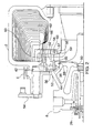
- FIG.1 shows a variable nozzle turbocharger employing multiple pivoting vanes in the nozzle.
- the turbocharger incorporates a turbine housing 2 which is mounted to a turbine flange 4 using a V-band coupling 6.
- the turbine flange is mounted to a center housing 8 using bolts 10.
- a compressor back plate 12 is mounted to the center housing opposite the turbine flange using bolts 14, and a compressor housing 16 is mounted to the back plate with a V-band coupling.
- the charge air compressor wheel 18 of the turbocharger is mounted to the shaft of a turbine wheel assembly 20.
- the shaft is supported by a bearing assembly in the center housing which, for the embodiment disclosed in the drawings, includes a pair of journal bearings 22 separated by a spacer 24 and a thrust collar 26 receiving thrust bearing 28.
- Appropriate lubrication channels are provided in the center housing for the bearings and shaft.
- a piston ring 30 provides a seal for the shaft at the turbine end while a carbon seal or equivalent labyrinth seal 32 provides a seal for the compressor end of the shaft.
- a seal ring 33 and seal washers 31 provide additional sealing between the center housing and compressor back plate.
- a disk shroud 21 is employed as a thermal baffle.
- the vanes 34 of the variable nozzle are supported by axles (not shown) extending into nozzle ring 36 which, in the embodiment shown, is supported in spaced relation to the turbine housing by a plurality of spacer pins 38 and fixed by a disk spring 40.
- the details of the actuation and support structure for the vanes is substantially as disclosed in US Patent 4,804,316 previously referenced.
- FIG. 2 The details of an embodiment of the present invention are shown in FIG. 2 wherein common components with the turbocharger of FIG.1 are commonly numbered.
- Each of the vanes 34 is partially supported by a first axle 50 which extends in close relation into and is rotatably supported by apertures 35 in the nozzle ring 36.
- the first axle extends through the nozzle ring and is attached to a vane arm 52 which is received in slots in the unison ring 42 for actuation of the vanes. Rotation of the unison ring is accomplished by an external crank and actuator linkage 54.
- a second axle 56 extends from each of the vanes, opposite and co-axial with the first axle.
- the second axle extends in close relation into and is rotatably supported by mating apertures 57 in an insert ring 58 which is recessed into the turbine housing and carried by a machined relief 59.
- the nozzle ring and insert ring form the bounding hub and shroud surfaces of the nozzle.
- Three precision hollow, circular spacers 60 and retaining bolts 62 are used to precisely locate and space the two rings and to secure the nozzle ring assembly to the turbine housing between the nozzle inlet and the nozzle outlet adjacent the turbine.
- the insert ring is free to rotate slightly to preclude any rotational mismatch of the two hole patterns in the rings.
- the pressure difference across the vanes can be resolved into a force acting substantially perpendicular to the center of pressure, which is at mid-span of the vanes.
- Two equal reaction forces, provided by the two axles on opposite sides of the vane, counterbalance the aerodynamic loading. These reaction forces are equally balanced and the peak reaction force is reduced 66% relative to the forces present in an identical cascade of cantilevered vanes.
- Axle loading and wear is much more uniform than in the cantilevered design, permitting the axle diameter to be reduced and, in turn, further reduction in the frictional moment arm is achieved.
- the axles are located at approximately 25% of the cord length of the vanes to obtain a substantially zero aerodynamic moment on the vanes with respect to the axles.
- Elimination of axial loading of the vanes is also addressed in the present invention by pressure balancing the two support axles for each of the vanes.
- Gas leakage from the inlet to the nozzle from the turbine volute through the various linkage and support elements associated with the nozzle ring ultimately results in a pressure in chamber 64, which acts on the end of the first axle.
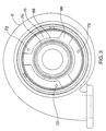
- exhaust gas pressure from the nozzle inlet is transmitted through radial channels 66 machined into the insert ring relief in the turbine housing.
- a annular channel 68 extends around the relief adjacent the axle apertures in the insert ring and adjoining the radial channels to transmit the gas pressure to the head of the second axle.
- a seal 69 is provided between the inner circumference of nozzle ring and a mating surface on the center housing to enhance the pressure balance between the two axles.
- the annular and radial channels are best seen in FIG. 3 which also shows the precision machined surfaces 70 of the relief in the turbine housing which support the insert ring. Tapped holes 72 receive the bolts 62 securing the nozzle ring assembly to the turbine housing.
- the radial and or annular channels are machined into the insert ring as opposed to the turbine housing.
- separate radial channels corresponding to and intersecting each aperture in the insert ring are machined in the insert ring or turbine housing.
- FIG.s 4 and 5 are force diagrams demonstrating the hysteresis in control of the nozzle vanes.
- curve 74 shows the hysteresis in a conventional cantilevered vane nozzle arrangement.
- Curve 76 demonstrates the improvement with the double axle support for the vanes.
- curve 78 shows the conventional cantilevered vane nozzle arrangement while curve 80 demonstrates the total improvement provided by the double axle support and pressure balancing of the present invention.
Landscapes
- Engineering & Computer Science (AREA)
- Mechanical Engineering (AREA)
- General Engineering & Computer Science (AREA)
- Supercharger (AREA)
- Control Of Turbines (AREA)
Claims (10)
- Turbine für einen Turbolader mit variabler Geometrie, die Folgendes umfasst:dadurch gekennzeichnet, dass sich die ersten mehreren Öffnungen im Düsenring vollständig durch den Düsenring und die mehreren Öffnungen im Einsatzring vollständig durch den Einsatzring erstrecken, und weiterhin mit:ein Turbinengehäuse (2) mit einem Abgas von einer Brennkraftmaschine empfangenden Diffusor und einem Düseneinlass;eine im Turbinengehäuse aufgenommene Turbine (20) zum Aufprall des Abgases von einem Düsenauslass zum Antrieb der Turbine;mehrere Leitschaufeln (34), die jeweils eine sich von einer Seite der Leitschaufel erstreckende erste Achse (50) und eine sich von einer gegenüberliegenden Seite der Leitschaufel, koaxial zur ersten Achse verlaufende zweite Achse (56) aufweisen;einen Düsenring (36) mit mehreren Öffnungen, die die ersten Achsen der mehreren Leitschaufeln eng aufnehmen;einen Einsatzring (58) mit mehreren Öffnungen, die die zweiten Achsen der mehreren Leitschaufeln eng aufnehmen;ein Mittel zur Befestigung des Düsenrings und des Einsatzrings in im Wesentlichen starrer, beabstandeter Beziehung zur Positionierung der Leitschaufeln zwischen dem Düseneinlass vom Diffusor und dem Düsenauslass neben der Turbine;ein Mittel zur Drehung der Leitschaufeln;einem ersten Mittel zur Übertragung von Abgasdruck zum Aufprall auf ein Ende der ersten Achse für jede Leitschaufel distal von der Leitschaufel;einem zweiten Mittel zur Übertragung von Abgasdruck zum Aufprall auf ein Ende der zweiten Achse für jede Leitschaufel distal von der Leitschaufel.
- Turbine nach Anspruch 1, bei der das erste Mittel zur Übertragung von Abgasdruck eine Kammer (64) neben dem Düsenring distal von den Leitschaufeln umfasst, wobei die Kammer in Druckverbindung mit dem Düseneinlass steht.
- Turbine nach Anspruch 1, bei der das zweite Mittel zur Übertragung von Abgasdruck sich von dem Düseneinlass zu den Öffnungen im Einsatzring erstreckende Kanäle (66) umfasst, welche die Öffnungen distal der Leitschaufeln in der Nähe des Endes der zweiten Achse schneiden.
- Turbine nach Anspruch 2, bei der die Kammer das Betätigungsmittel für die Leitschaufeln aufnimmt.
- Turbine nach Anspruch 3, bei der die Kanäle mindestens einen radialen Kanal (66) im Turbinengehäuse umfassen, der sich zwischen dem Düseneinlass und einem ringförmigen Kanal (68) in dem Turbinengehäuse neben dem Einsatzring erstreckt und die Öffnungen im Einsatzring schneidet.
- Turbine nach Anspruch 4, bei der sich die ersten Achsen durch die Öffnungen im Düsenring erstrecken und das Betätigungsmittel Folgendes umfasst:an den ersten Achsen befestigte und sich senkrecht zu ihnen erstreckende Leitschaufelarme (52), die in Schlitzen in einem Betätigungsring (42) aufgenommen sind; undeine Kurbelschwinge (54) zum Drehen des Betätigungsrings.
- Turbine nach Anspruch 4, bei der die Kammer (64) zwischen dem Turbinengehäuse und einem mittleren Gehäuse (8) für den am Turbinengehäuse befestigten Turbolader angeordnet ist.
- Turbine nach Anspruch 7, weiterhin mit einer Dichtung (69), die zwischen einem Innenumfang des Düsenrings und einer Gegenfläche an dem mittleren Gehäuse angeordnet ist.
- Turbine nach Anspruch 1, bei der das Mittel zur Befestigung des Düsenrings und des Einsatzrings Folgendes umfasst:mehrere starre Hohlabstandsstücke (60), die zwischen dem Düsenring und dem Einsatzring angeordnet sind; undmehrere sich durch den Düsenring, die Abstandsstücke und den Einsatzring erstreckende Schrauben (62), die mit Gegenlöchern im Turbinengehäuse verschraubt sind.
- Turbine nach Anspruch 9, bei der der Einsatzring in einer maschinell herausgearbeiteten ringförmigen Aussparung im Turbinengehäuse aufgenommen ist.
Applications Claiming Priority (5)
| Application Number | Priority Date | Filing Date | Title |
|---|---|---|---|
| US4125697P | 1997-03-17 | 1997-03-17 | |
| US41256P | 1997-03-17 | ||
| US09/033,274 US5947681A (en) | 1997-03-17 | 1998-03-02 | Pressure balanced dual axle variable nozzle turbocharger |
| US33274 | 1998-03-02 | ||
| PCT/US1998/005119 WO1998041737A1 (en) | 1997-03-17 | 1998-03-16 | Pressure balanced dual axle variable nozzle turbocharger |
Publications (2)
| Publication Number | Publication Date |
|---|---|
| EP1009918A1 EP1009918A1 (de) | 2000-06-21 |
| EP1009918B1 true EP1009918B1 (de) | 2004-11-10 |
Family
ID=26709493
Family Applications (1)
| Application Number | Title | Priority Date | Filing Date |
|---|---|---|---|
| EP98909190A Expired - Lifetime EP1009918B1 (de) | 1997-03-17 | 1998-03-16 | Turbolader mit zweiachsigen verstellbaren leitschaufeln mit druckausgleich |
Country Status (7)
| Country | Link |
|---|---|
| US (1) | US5947681A (de) |
| EP (1) | EP1009918B1 (de) |
| JP (1) | JP3992750B2 (de) |
| AU (1) | AU6703598A (de) |
| DE (1) | DE69827504T2 (de) |
| ES (1) | ES2229482T3 (de) |
| WO (1) | WO1998041737A1 (de) |
Cited By (2)
| Publication number | Priority date | Publication date | Assignee | Title |
|---|---|---|---|---|
| DE102007056154A1 (de) | 2007-11-21 | 2009-05-28 | Bosch Mahle Turbo Systems Gmbh & Co. Kg | Ladeeinrichtung |
| RU2774930C1 (ru) * | 2021-10-26 | 2022-06-24 | Общество с ограниченной ответственностью «АЭРОГАЗ» (ООО «АЭРОГАЗ») | Способ работы турбодетандерной энергетической установки |
Families Citing this family (35)
| Publication number | Priority date | Publication date | Assignee | Title |
|---|---|---|---|---|
| CA2397445C (en) | 2000-01-14 | 2008-03-18 | Alliedsignal Turbo S.A. | Turbocharger with sliding blades having combined dynamic surfaces and heat screen and uncoupled axial actuating device |
| US6430929B2 (en) | 2000-03-03 | 2002-08-13 | Honeywell International Inc. | Turbocharger with integrated exhaust gas recirculation valve |
| US6287091B1 (en) * | 2000-05-10 | 2001-09-11 | General Motors Corporation | Turbocharger with nozzle ring coupling |
| WO2002006636A1 (fr) | 2000-07-19 | 2002-01-24 | Honeywell Garrett Sa | Turbocompresseur a ailettes coulissantes avec ailettes graduees |
| DE10048105A1 (de) * | 2000-09-28 | 2002-04-11 | Daimler Chrysler Ag | Angasturbolader für eine Brennkraftmaschine mit variabler Turbinengeometrie |
| DE10050157B4 (de) * | 2000-10-11 | 2010-12-02 | Ihi Charging Systems International Gmbh | Leitgitter mit verstellbaren Leitschaufeln für einen Abgasturbolader |
| GB0025244D0 (en) | 2000-10-12 | 2000-11-29 | Holset Engineering Co | Turbine |
| US7024855B2 (en) * | 2000-11-30 | 2006-04-11 | Honeywell International, Inc. | Variable geometry turbocharger with sliding piston |
| DE10209484B4 (de) * | 2002-03-05 | 2004-06-24 | Borgwarner Turbo Systems Gmbh | Turbolader für Fahrzeuge mit verbesserter Aufhängung für den Betätigungsmechanismus der variablen Düsen |
| EP1394364B1 (de) | 2002-08-26 | 2006-03-08 | BorgWarner Inc. | Turbolader und Schaufellagerring hierfür |
| US7946116B2 (en) * | 2002-09-05 | 2011-05-24 | Honeywell International, Inc. | Turbocharger comprising a variable nozzle device |
| WO2004022924A1 (en) | 2002-09-06 | 2004-03-18 | Honeywell Garrett Sa | Self regulating slide vane turbocharger |
| DE10325985A1 (de) * | 2003-06-07 | 2004-12-23 | Ihi Charging Systems International Gmbh | Leitapparat für eine Abgasturbine |
| EP1536103B1 (de) * | 2003-11-28 | 2013-09-04 | BorgWarner, Inc. | Strömungsmaschine mit Leitgitter und Befestigungseinrichtung dafür |
| DE102004023212A1 (de) * | 2004-05-11 | 2005-12-08 | Volkswagen Ag | Abgasturbolader für eine Brennkraftmaschine mit variabler Turbinengeometrie |
| DE102004023208A1 (de) * | 2004-05-11 | 2005-12-08 | Volkswagen Ag | Abgasturbolader für eine Brennkraftmaschine mit variabler Turbinengeometrie |
| DE102004023280A1 (de) * | 2004-05-11 | 2005-12-01 | Volkswagen Ag | Abgasturbolader für eine Brennkraftmaschine mit variabler Turbinengeometrie |
| US20060029755A1 (en) * | 2004-08-03 | 2006-02-09 | Tkacik Peter T | Alternative moisture and temperature resistant forming tubes |
| DE602005020701D1 (de) * | 2005-10-18 | 2010-05-27 | Honeywell Int Inc | Turbolader und patrone mit variabler düse dafür |
| US20070175214A1 (en) * | 2006-01-30 | 2007-08-02 | Reisdorf Paul W | Turbocharger having divided housing with nozzle vanes |
| DE102006018055A1 (de) * | 2006-04-19 | 2007-10-31 | Daimlerchrysler Ag | Abgasturbolader für eine Brennkraftmaschine |
| US7553127B2 (en) * | 2006-06-13 | 2009-06-30 | Honeywell International Inc. | Variable nozzle device |
| US8112995B2 (en) * | 2006-06-19 | 2012-02-14 | Turbo Energy Limited | Turbocharger with variable turbine geometry |
| JP2008215083A (ja) * | 2007-02-28 | 2008-09-18 | Mitsubishi Heavy Ind Ltd | 可変容量型排気ターボ過給機における可変ノズル機構部取付構造 |
| US8024919B2 (en) * | 2007-07-31 | 2011-09-27 | Caterpillar Inc. | Engine system, operating method and control strategy for aftertreatment thermal management |
| US20110067680A1 (en) * | 2009-09-22 | 2011-03-24 | Gm Global Technology Operations, Inc. | Turbocharger and Air Induction System Incorporating the Same and Method of Making and Using the Same |
| US9759228B2 (en) * | 2009-10-16 | 2017-09-12 | GM Global Technology Operations LLC | Turbocharger and air induction system incorporating the same and method of using the same |
| DE102009047006A1 (de) | 2009-11-23 | 2011-05-26 | Robert Bosch Gmbh | Aufladeeinrichtung |
| DE102011119879A1 (de) * | 2011-12-01 | 2013-06-06 | Ihi Charging Systems International Gmbh | Fluidenergiemaschine, insbesondere für einen Abgasturbolader eines Kraftwagens |
| JP2015537163A (ja) * | 2012-12-14 | 2015-12-24 | ボーグワーナー インコーポレーテッド | 排気ガスターボチャージャの制御構成部 |
| CN104956045A (zh) * | 2013-02-19 | 2015-09-30 | 博格华纳公司 | 具有轴流式转动叶片的涡轮增压器内部涡轮机隔热屏 |
| US10240480B2 (en) * | 2014-11-21 | 2019-03-26 | Borgwarner Inc. | Variable turbine geometry vane with single-axle, self-centering pivot feature |
| US10590795B2 (en) * | 2017-10-17 | 2020-03-17 | United Technologies Corporation | Vane arm with tri-wedge circular pocket |
| US10393065B2 (en) * | 2017-11-09 | 2019-08-27 | United Technologies Corporation | Variable nozzle apparatus |
| DE102022105348A1 (de) | 2022-03-08 | 2023-09-14 | Avl Schrick Gmbh | Abgasturboladerfixierung |
Family Cites Families (18)
| Publication number | Priority date | Publication date | Assignee | Title |
|---|---|---|---|---|
| US1823702A (en) * | 1928-05-24 | 1931-09-15 | Allis Chalmers Mfg Co | Hydraulic machine |
| US1860618A (en) * | 1930-08-08 | 1932-05-31 | Allis Chalmers Mfg Co | Hydraulic turbine |
| US1942589A (en) * | 1932-06-21 | 1934-01-09 | James Leffel & Company | Hydraulic turbine |
| DE2855919B1 (de) * | 1978-12-23 | 1979-09-20 | Basf Farben & Fasern | Plastisole |
| US4490622A (en) * | 1979-05-11 | 1984-12-25 | Osborn Norbert L | Turbocharger and adaptations thereof |
| US4436481A (en) * | 1981-06-15 | 1984-03-13 | The Garrett Corporation | Intake vortex whistle silencing apparatus and methods |
| SE451620B (sv) * | 1983-03-18 | 1987-10-19 | Flaekt Ab | Forfarande for framstellning av ledskenekrans for aterstromningskanal vid axialflektar |
| US4643640A (en) * | 1984-04-20 | 1987-02-17 | The Garrett Corporation | Gas seal vanes of variable nozzle turbine |
| US4659295A (en) * | 1984-04-20 | 1987-04-21 | The Garrett Corporation | Gas seal vanes of variable nozzle turbine |
| US4654941A (en) * | 1984-04-20 | 1987-04-07 | The Garrett Corporation | Method of assembling a variable nozzle turbocharger |
| JPS61185622A (ja) * | 1985-02-13 | 1986-08-19 | Toyota Motor Corp | 可変ノズル付タ−ボチヤ−ジヤの過給圧制御装置 |
| DE3541508C1 (de) * | 1985-11-23 | 1987-02-05 | Kuehnle Kopp Kausch Ag | Abgasturbolader |
| US4804316A (en) * | 1985-12-11 | 1989-02-14 | Allied-Signal Inc. | Suspension for the pivoting vane actuation mechanism of a variable nozzle turbocharger |
| US4679984A (en) * | 1985-12-11 | 1987-07-14 | The Garrett Corporation | Actuation system for variable nozzle turbine |
| US4741666A (en) * | 1985-12-23 | 1988-05-03 | Ishikawajima-Harima Jukogyo Kabushiki Kaisha | Variable displacement turbocharger |
| US5028208A (en) * | 1989-01-10 | 1991-07-02 | Ishikawajima-Harima Jukogyo Kabushiki Kaisha | Nozzle blade angle adjustment device for variable geometry turbocharger |
| DE3941715A1 (de) * | 1989-12-18 | 1991-06-20 | Porsche Ag | Abgasturbolader fuer eine brennkraftmaschine |
| US5564895A (en) * | 1995-04-26 | 1996-10-15 | Rotoflow Corporation | Active automatic clamping control |
-
1998
- 1998-03-02 US US09/033,274 patent/US5947681A/en not_active Expired - Lifetime
- 1998-03-16 EP EP98909190A patent/EP1009918B1/de not_active Expired - Lifetime
- 1998-03-16 JP JP54067598A patent/JP3992750B2/ja not_active Expired - Lifetime
- 1998-03-16 ES ES98909190T patent/ES2229482T3/es not_active Expired - Lifetime
- 1998-03-16 AU AU67035/98A patent/AU6703598A/en not_active Abandoned
- 1998-03-16 DE DE69827504T patent/DE69827504T2/de not_active Expired - Lifetime
- 1998-03-16 WO PCT/US1998/005119 patent/WO1998041737A1/en active IP Right Grant
Cited By (3)
| Publication number | Priority date | Publication date | Assignee | Title |
|---|---|---|---|---|
| DE102007056154A1 (de) | 2007-11-21 | 2009-05-28 | Bosch Mahle Turbo Systems Gmbh & Co. Kg | Ladeeinrichtung |
| US8845279B2 (en) | 2007-11-21 | 2014-09-30 | Bosch Mahle Turbo Systems Gmbh & Co. Kg | Supercharger device |
| RU2774930C1 (ru) * | 2021-10-26 | 2022-06-24 | Общество с ограниченной ответственностью «АЭРОГАЗ» (ООО «АЭРОГАЗ») | Способ работы турбодетандерной энергетической установки |
Also Published As
| Publication number | Publication date |
|---|---|
| DE69827504T2 (de) | 2005-11-24 |
| WO1998041737A1 (en) | 1998-09-24 |
| EP1009918A1 (de) | 2000-06-21 |
| DE69827504D1 (de) | 2004-12-16 |
| US5947681A (en) | 1999-09-07 |
| JP3992750B2 (ja) | 2007-10-17 |
| AU6703598A (en) | 1998-10-12 |
| ES2229482T3 (es) | 2005-04-16 |
| JP2001516417A (ja) | 2001-09-25 |
Similar Documents
| Publication | Publication Date | Title |
|---|---|---|
| EP1009918B1 (de) | Turbolader mit zweiachsigen verstellbaren leitschaufeln mit druckausgleich | |
| CA2423755C (en) | Variable geometry turbocharger with sliding piston | |
| US5441383A (en) | Variable exhaust driven turbochargers | |
| KR100643093B1 (ko) | 스텝 베인을 가진 슬라이드 베인 터보차저 | |
| EP0226444B1 (de) | Turbolader mit verstellbaren Leitschaufeln | |
| US4804316A (en) | Suspension for the pivoting vane actuation mechanism of a variable nozzle turbocharger | |
| US7001142B2 (en) | Turbocharger for vehicle with improved suspension of the actuating mechanism for variable nozzles | |
| CA2416331C (en) | Variable geometry turbocharger with sheet metal shell | |
| EP3026225B1 (de) | Turbolader mit variabler geometrie und verfahren zur herstellung | |
| EP1352157B1 (de) | Turbolader variabler Geometrie mit verbesserter Schaufelverstellung | |
| US20110123316A1 (en) | Variable geometry turbine | |
| US6962481B2 (en) | Turbocharger for vehicle with improved suspension of the actuating mechanism for variable nozzles | |
| EP0248624B1 (de) | Turbine mit variablem Schluckvermögen | |
| JP2017515051A (ja) | 可変ジオメトリタービンアセンブリ | |
| EP2035673B1 (de) | Verstellbarer leitschaufelmechanismus für turbolader | |
| WO2009153546A2 (en) | Variable geometry turbine | |
| EP4377556A1 (de) | Turbine mit variabler geometrie | |
| EP3708844B1 (de) | Turbolader und lagergehäuse dafür | |
| EP0111782B1 (de) | Turbolader mit einem Mitnehmer um das Kompressorrad auf der Welle zu sichern | |
| WO2024157030A1 (en) | Variable geometry turbine | |
| JPH0416607B2 (de) | ||
| JPH0348335B2 (de) |
Legal Events
| Date | Code | Title | Description |
|---|---|---|---|
| PUAI | Public reference made under article 153(3) epc to a published international application that has entered the european phase |
Free format text: ORIGINAL CODE: 0009012 |
|
| 17P | Request for examination filed |
Effective date: 19990913 |
|
| AK | Designated contracting states |
Kind code of ref document: A1 Designated state(s): DE ES FR GB IT SE |
|
| 17Q | First examination report despatched |
Effective date: 20020206 |
|
| GRAH | Despatch of communication of intention to grant a patent |
Free format text: ORIGINAL CODE: EPIDOS IGRA |
|
| RAP1 | Party data changed (applicant data changed or rights of an application transferred) |
Owner name: HONEYWELL INTERNATIONAL INC. |
|
| GRAS | Grant fee paid |
Free format text: ORIGINAL CODE: EPIDOSNIGR3 |
|
| GRAA | (expected) grant |
Free format text: ORIGINAL CODE: 0009210 |
|
| AK | Designated contracting states |
Kind code of ref document: B1 Designated state(s): DE ES FR GB IT SE |
|
| REG | Reference to a national code |
Ref country code: GB Ref legal event code: FG4D |
|
| REF | Corresponds to: |
Ref document number: 69827504 Country of ref document: DE Date of ref document: 20041216 Kind code of ref document: P |
|
| REG | Reference to a national code |
Ref country code: SE Ref legal event code: TRGR |
|
| REG | Reference to a national code |
Ref country code: ES Ref legal event code: FG2A Ref document number: 2229482 Country of ref document: ES Kind code of ref document: T3 |
|
| ET | Fr: translation filed | ||
| PLBE | No opposition filed within time limit |
Free format text: ORIGINAL CODE: 0009261 |
|
| STAA | Information on the status of an ep patent application or granted ep patent |
Free format text: STATUS: NO OPPOSITION FILED WITHIN TIME LIMIT |
|
| 26N | No opposition filed |
Effective date: 20050811 |
|
| PGFP | Annual fee paid to national office [announced via postgrant information from national office to epo] |
Ref country code: ES Payment date: 20130325 Year of fee payment: 16 |
|
| REG | Reference to a national code |
Ref country code: ES Ref legal event code: FD2A Effective date: 20150427 |
|
| PG25 | Lapsed in a contracting state [announced via postgrant information from national office to epo] |
Ref country code: ES Free format text: LAPSE BECAUSE OF NON-PAYMENT OF DUE FEES Effective date: 20140317 |
|
| REG | Reference to a national code |
Ref country code: FR Ref legal event code: PLFP Year of fee payment: 19 |
|
| REG | Reference to a national code |
Ref country code: FR Ref legal event code: PLFP Year of fee payment: 20 |
|
| PGFP | Annual fee paid to national office [announced via postgrant information from national office to epo] |
Ref country code: FR Payment date: 20170222 Year of fee payment: 20 Ref country code: SE Payment date: 20170307 Year of fee payment: 20 |
|
| PGFP | Annual fee paid to national office [announced via postgrant information from national office to epo] |
Ref country code: GB Payment date: 20170223 Year of fee payment: 20 |
|
| PGFP | Annual fee paid to national office [announced via postgrant information from national office to epo] |
Ref country code: IT Payment date: 20170309 Year of fee payment: 20 |
|
| PGFP | Annual fee paid to national office [announced via postgrant information from national office to epo] |
Ref country code: DE Payment date: 20170331 Year of fee payment: 20 |
|
| REG | Reference to a national code |
Ref country code: DE Ref legal event code: R071 Ref document number: 69827504 Country of ref document: DE |
|
| REG | Reference to a national code |
Ref country code: GB Ref legal event code: PE20 Expiry date: 20180315 |
|
| PG25 | Lapsed in a contracting state [announced via postgrant information from national office to epo] |
Ref country code: GB Free format text: LAPSE BECAUSE OF EXPIRATION OF PROTECTION Effective date: 20180315 |
|
| REG | Reference to a national code |
Ref country code: SE Ref legal event code: EUG |