EP1008818A2 - Kondensatabführungssystem für eine luftgekühlte Klimaanlage mit einem Gebläse - Google Patents
Kondensatabführungssystem für eine luftgekühlte Klimaanlage mit einem Gebläse Download PDFInfo
- Publication number
- EP1008818A2 EP1008818A2 EP99630088A EP99630088A EP1008818A2 EP 1008818 A2 EP1008818 A2 EP 1008818A2 EP 99630088 A EP99630088 A EP 99630088A EP 99630088 A EP99630088 A EP 99630088A EP 1008818 A2 EP1008818 A2 EP 1008818A2
- Authority
- EP
- European Patent Office
- Prior art keywords
- condensate
- fan
- coil
- collecting surface
- condenser
- Prior art date
- Legal status (The legal status is an assumption and is not a legal conclusion. Google has not performed a legal analysis and makes no representation as to the accuracy of the status listed.)
- Withdrawn
Links
Images


Classifications
-
- F—MECHANICAL ENGINEERING; LIGHTING; HEATING; WEAPONS; BLASTING
- F24—HEATING; RANGES; VENTILATING
- F24F—AIR-CONDITIONING; AIR-HUMIDIFICATION; VENTILATION; USE OF AIR CURRENTS FOR SCREENING
- F24F1/00—Room units for air-conditioning, e.g. separate or self-contained units or units receiving primary air from a central station
- F24F1/06—Separate outdoor units, e.g. outdoor unit to be linked to a separate room comprising a compressor and a heat exchanger
- F24F1/42—Separate outdoor units, e.g. outdoor unit to be linked to a separate room comprising a compressor and a heat exchanger characterised by the use of the condensate, e.g. for enhanced cooling
-
- F—MECHANICAL ENGINEERING; LIGHTING; HEATING; WEAPONS; BLASTING
- F24—HEATING; RANGES; VENTILATING
- F24F—AIR-CONDITIONING; AIR-HUMIDIFICATION; VENTILATION; USE OF AIR CURRENTS FOR SCREENING
- F24F13/00—Details common to, or for air-conditioning, air-humidification, ventilation or use of air currents for screening
- F24F13/22—Means for preventing condensation or evacuating condensate
- F24F13/222—Means for preventing condensation or evacuating condensate for evacuating condensate
- F24F13/224—Means for preventing condensation or evacuating condensate for evacuating condensate in a window-type room air conditioner
-
- F—MECHANICAL ENGINEERING; LIGHTING; HEATING; WEAPONS; BLASTING
- F24—HEATING; RANGES; VENTILATING
- F24F—AIR-CONDITIONING; AIR-HUMIDIFICATION; VENTILATION; USE OF AIR CURRENTS FOR SCREENING
- F24F13/00—Details common to, or for air-conditioning, air-humidification, ventilation or use of air currents for screening
- F24F13/22—Means for preventing condensation or evacuating condensate
- F24F13/222—Means for preventing condensation or evacuating condensate for evacuating condensate
- F24F2013/225—Means for preventing condensation or evacuating condensate for evacuating condensate by evaporating the condensate in the cooling medium, e.g. in air flow from the condenser
Definitions
- This invention relates generally to air conditioning systems and, more particularly, to a condensate disposal system for a packaged terminal air conditioner.
- Warm air is also frequently humid, i.e. it contains entrained water vapor.
- the system refrigerant evaporator reduces the temperature of the air to a level below its dew point. In that condition, water vapor condenses on the evaporator.
- Some means must be provided to dispose of this condensate.
- small unitary air conditioners such as window or through-the-wall mounted room air conditioners, a common means to accomplish condensate disposal is by providing a condensate collection and drain path that communicates between the indoor and outdoor sections of the air conditioner.
- Condensate formed on the system evaporator drains into a collector in the indoor section and then flows to a location under or near the condenser fan in the outdoor section.
- a condensate distribution device is then provided to pick up the condensate and cause it to flow onto the hot surfaces of the system condenser where the condensate water evaporates.
- Common condensate distribution schemes include vortex impellers or aspirators, slinger rings, mechanical pumps or specially designed fan blade tips.
- a slinger arrangement associated with a condenser fan.
- a blow-through propeller fan coil configuration is used and the condensate collects at a location where the fan structure causes the condensate to be splashed onto the condenser coil, where it is evaporated, thereby providing cooling to the condenser.
- the effectiveness of such a condensate disposal system i.e. wherein a propeller fan is used to distribute the cold condensate generated by the indoor coil to be evaporated on the hot outdoor coil, is dependent on the following factors: (a) the distribution area of condensate onto the outdoor coil surface; (b) the temperature of that condensate spray; (c) the volume of condensate distributed to the coil and; (d) the amount of condensate that is held in the sump.
- the sump where the water is collected from below the evaporator coil and flows to the condenser side for distribution, comprises a relatively large, flat pan which requires the accumulation of a considerable amount of condensate in order to rise to the level where it can be distributed onto the condenser coil.
- the temperature of the water when it finally reaches the distribution system is substantially warmer than the temperature of the condensate coming off the evaporator coil, thereby lowering the efficiency of the unit.
- the condensate distribution approaches that have been used tend to provide a relatively poor distribution of condensate across the face of the condenser coil.
- the slinger ring tends to lift the condensate and have it blown by the fan blades into the condenser coil in a relatively small concentrated area rather than over the entire face of the condenser coil.
- not all of the water lifted from the condensate collector is carried into the fan discharge.
- Some, in the form of droplets, is thrown radially outward until it impacts the system enclosure or other structural components, particularly when the fan is operating at a higher speed.
- Shrouds may be used to direct the droplets onto the condenser rather than on the surrounding system structures, but these structures add expense and complication.
- a packaged terminal air conditioner is provided with a condensate collecting surface below the evaporator coil and a second condensate collecting surface below the condenser coil, with the second surface being vertically lower than the first.
- a narrow channel is provided to interconnect the two surfaces such that all of the condensate collecting on the first surface runs off onto the second surface where it is picked up by the condensate distribution system and deposited on the condenser coil.
- the second condensation collection surface is of minimal size, i.e. generally only large enough to contain the condenser coil, such that the volume of condensate collected and held prior to the distribution occurring is minimized.
- a lifting wall structure which extends upwardly from the condensate collecting surface and closely surrounds the lower part of the fan blade so as to create an area of decreasing pressure between the fan blade and the lifting wall so as to cause the condensate to be lifted upwardly where it can be drawn into the fan blade and distributed, relatively uniformly, over the surface of the condenser coil.
- the unit includes an indoor section 11, an outdoor section 12 and a transition section 13 that is located in the wall of the building.
- the outdoor section 12 includes a condenser coil 14 and a propeller fan 16 for circulating outside air over the condenser coil 14 for purposes of condensing the refrigerant in a conventional manner as a part of the refrigeration cycle.
- the refrigerant is compressed by a compressor 17 and then passed through the condenser coil 14 where it is condensed.
- the condensed refrigerant then passes to the indoor section 12 where it is expanded into the evaporator coil prior to being returned to the compressor 17 to complete the cycle.
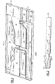
- FIGs 2-7 show various views of the base pan 18 and of the condensate pan 19.
- the base pan 18 includes raised areas 21, 22, 23 and 24.
- Raised areas 21 and 22 are provided for the mounting of components, such as the compressor, thereon.
- Raised surfaces 23 and 24 are provided as fill structures to reduce the area in which condensate accumulates in the area of the condenser coil.
- the adjacent grooves 25 and 30 are provided to seal between the high and low pressure areas on either side of the shroud.
- Also provided in base pan 18 are the vertically depressed surfaces 26, 27, 28 and 29, laterally spaced across the base pan 18.
- a transversely extending passageway or drainway 31 to facilitate drainage of condensate into the depressed surface 29, also referred to as a condensate collecting surface, in a manner to be more fully described hereinafter.
- the condensate pan 19 which is shown in Figures 2-6, is installed in the outdoor section portion of the base pan 18 as shown. Drainways 32 and 33 extend transversely from one edge thereof, with the drainway 32 being aligned with, and draining into, drainway 31 of the base pan 18. Drainway 33 extends to raised area 22 as shown.
- the transverse profile of the condensate pan 19 is progressively lower in height as it extends across surfaces 36, 37 and 38 and finally to the drainway 32 (See Figure 3). It will be seen while the surfaces 36, 37 and 32 are substantially flat, the surface 38 is sloping downwardly to the drainway 32. It will also be seen by reference to Figure 6 that the surface 36 slopes downwardly as it extends longitudinally inwardly from the ends to the middle.
- the drainway 33 is sloped in the opposite direction from that of the surface 38 such that the condensate that forms on the tubing which passes between the outdoor and indoor sections, tends to flow off the tube, down the drainway 33, to the surface 37, and eventually to the condensate collection surface 29.
- the propeller fan 16 is driven by the motor 39 and is disposed adjacent the condenser coil 14.
- a shroud 41 closely surrounds the fan 16 in a well known manner.
- the fan 16 may have a slinger-ring as shown in Figure 1, or it may have no ring as shown in Figure 9.
- Located on the upstream side of the fan 16 is a gusset 42 which is mounted by way of fasteners 43 to a frame 44.
- the gusset as shown in full in Figure 8, includes top member 46, upper air flow baffle member 47, snow shield member 48, lower air flow baffle member 49, water spray wall 51, and a condensate trough cover 52.
- the gusset 42 is so located that the snow shield member 48 wraps around, but does not directly contact the motor 48, and the water spray wall 51 is located just upstream of the fan 16 at the lower portion thereof as shown in Figure 9. The functions of the various sections of the gusset 42 will not be described.
- the snow shield member 48 thus serves to prevent this occurrence by shielding the motor from direct contact with the snow.
- the water spray wall 51 is strategically located with respect to the fan 16 such that the pressure between the fan 16 and the wall 51 is progressively lower in the radially inward direction. This is caused by the vortex effect which occurs because of faster moving air having less pressure than still air. The effect is that the condensate in the condensate collecting surface 29 of the base pan 18 is cause to be "sucked up" into the radially inner portion of the fan 16 so as to be more evenly distributed across the condenser coil 14 than would otherwise occur if the condensate were contacted only by the radially outer portions of the fan 16.
- the water spray wall 51 should be placed as closely as possible to the fan 16 and should approximate as closely as possible the same shape in the vertical plane.
- the condensate trough cover 52 at the lower end of the gusset 42 is provided to cover the drainway 31 leading to the condensate collecting surface 29 so as to thereby prevent the entry of outside contaminates such as leaves and dirt.
Landscapes
- Engineering & Computer Science (AREA)
- Chemical & Material Sciences (AREA)
- Combustion & Propulsion (AREA)
- Mechanical Engineering (AREA)
- General Engineering & Computer Science (AREA)
- Physics & Mathematics (AREA)
- Thermal Sciences (AREA)
- Devices For Blowing Cold Air, Devices For Blowing Warm Air, And Means For Preventing Water Condensation In Air Conditioning Units (AREA)
Applications Claiming Priority (2)
| Application Number | Priority Date | Filing Date | Title |
|---|---|---|---|
| US208796 | 1998-12-10 | ||
| US09/208,796 US6085539A (en) | 1998-12-10 | 1998-12-10 | Condensate disposal system for an air cooled air conditioning unit with a propeller fan |
Publications (2)
| Publication Number | Publication Date |
|---|---|
| EP1008818A2 true EP1008818A2 (de) | 2000-06-14 |
| EP1008818A3 EP1008818A3 (de) | 2002-05-22 |
Family
ID=22776101
Family Applications (1)
| Application Number | Title | Priority Date | Filing Date |
|---|---|---|---|
| EP99630088A Withdrawn EP1008818A3 (de) | 1998-12-10 | 1999-11-19 | Kondensatabführungssystem für eine luftgekühlte Klimaanlage mit einem Gebläse |
Country Status (2)
| Country | Link |
|---|---|
| US (1) | US6085539A (de) |
| EP (1) | EP1008818A3 (de) |
Cited By (4)
| Publication number | Priority date | Publication date | Assignee | Title |
|---|---|---|---|---|
| US7228698B2 (en) * | 2005-06-30 | 2007-06-12 | Premark Feg L.L.C. | Refrigeration unit |
| CN103512107A (zh) * | 2013-10-12 | 2014-01-15 | 胡达广 | 余热回收高效节能空调 |
| CN112710077A (zh) * | 2020-12-30 | 2021-04-27 | 佛山市顺德区美的电子科技有限公司 | 用于空调器的水处理装置和空调器 |
| US20260029155A1 (en) * | 2024-07-25 | 2026-01-29 | Haier Us Appliance Solutions, Inc. | Condensate management system for an air conditioner appliance |
Families Citing this family (22)
| Publication number | Priority date | Publication date | Assignee | Title |
|---|---|---|---|---|
| US20030228142A1 (en) * | 1998-11-16 | 2003-12-11 | Reiker Kenneth H. | Ceiling mounted heating and cooling device and method therefor |
| US6345511B1 (en) * | 1999-02-25 | 2002-02-12 | Kooltronic, Incorporated | Air handling apparatus |
| DE60027522T2 (de) * | 1999-11-22 | 2006-09-07 | Calsonic Kansei Corp. | Fahrzeugklimaanlage |
| US6363735B1 (en) * | 2000-08-17 | 2002-04-02 | Carrier Corporation | Air conditioner condenser orifice member having condensate suction port |
| AUPR428001A0 (en) * | 2001-04-06 | 2001-05-17 | OYL Research and Development Centre SDN.BHD. (a company incorporated under the laws of Malaysia) | Room air-conditioner |
| US6430955B1 (en) * | 2001-05-16 | 2002-08-13 | Carrier Corporation | Condensate removal system |
| US6381978B1 (en) | 2001-05-16 | 2002-05-07 | Carrier Corporation | Base pan assembly for air conditioner |
| CN100414203C (zh) * | 2003-12-23 | 2008-08-27 | 乐金电子(天津)电器有限公司 | 空调器冷却室内机电机的装置 |
| EP1910759A4 (de) * | 2005-07-29 | 2010-03-24 | Carrier Corp | Kondensatablaufanordnung für eine verdampfereinheit |
| WO2007012160A2 (en) * | 2005-07-29 | 2007-02-01 | Carrier Corporation | Condensate drain pan for an evaporator unit |
| CN101802518B (zh) * | 2007-09-18 | 2012-06-06 | 开利公司 | 用于空调单元的冷凝器组件 |
| KR101542389B1 (ko) * | 2009-02-05 | 2015-08-06 | 엘지전자 주식회사 | 히트펌프모듈 및 히트펌프모듈을 이용한 건조장치 |
| US8490438B2 (en) * | 2009-02-05 | 2013-07-23 | Lg Electronics Inc. | Laundry treatment device |
| EP2398948B1 (de) * | 2009-02-23 | 2018-09-12 | LG Electronics Inc. | Waschmaschine |
| EP2398947B1 (de) * | 2009-02-23 | 2016-10-26 | LG Electronics Inc. | Waschmaschine/trockner |
| KR101603106B1 (ko) * | 2009-03-03 | 2016-03-14 | 엘지전자 주식회사 | 세탁 장치 |
| CN102914034B (zh) * | 2011-08-04 | 2014-12-17 | 珠海格力电器股份有限公司 | 空调及其换气排水装置、换气排水管 |
| US10828964B2 (en) | 2016-02-23 | 2020-11-10 | Carrier Corporation | Redistribution of condensate for increased cooling capacity |
| US10207807B2 (en) * | 2016-04-13 | 2019-02-19 | The Boeing Company | Condensate removal system of an aircraft cooling system |
| US10775057B2 (en) * | 2018-08-20 | 2020-09-15 | Therma-Stor, Llc | Dehumidification drainage system with mist eliminator |
| CN111750598B (zh) * | 2019-03-29 | 2025-03-14 | 青岛海尔特种电冰柜有限公司 | 一种制冷设备的排水装置及制冷设备 |
| US12228328B2 (en) | 2020-09-24 | 2025-02-18 | Illinois Tool Works Inc. | Refrigerated device with enhanced condensate evaporation |
Family Cites Families (10)
| Publication number | Priority date | Publication date | Assignee | Title |
|---|---|---|---|---|
| US3724233A (en) * | 1972-02-17 | 1973-04-03 | Gen Motors Corp | Molded plastic base pan for room air conditioner |
| US4067206A (en) * | 1976-09-15 | 1978-01-10 | Admiral Corporation | Condensate evaporation system for air conditioners |
| JPS5436050A (en) * | 1977-08-26 | 1979-03-16 | Gen Corp | Air conditioner |
| US4382369A (en) * | 1981-09-08 | 1983-05-10 | General Electric Company | Air conditioning apparatus |
| GB2129532B (en) * | 1982-10-29 | 1986-03-26 | Mitsubishi Electric Corp | Integral type air conditioning device |
| JPS59119123A (ja) * | 1982-12-27 | 1984-07-10 | Matsushita Electric Ind Co Ltd | 空気調和機のドレン水処理装置 |
| JPS60251325A (ja) * | 1984-05-25 | 1985-12-12 | Mitsubishi Electric Corp | 空気調和機 |
| US5272886A (en) * | 1990-01-19 | 1993-12-28 | Matsushita Electric Industrial Co., Ltd. | Moisture disposing device for use in a self-contained air conditioner |
| US5461879A (en) * | 1994-04-19 | 1995-10-31 | Carrier Corporation | Air conditioner condensate slinger |
| US5669230A (en) * | 1996-04-12 | 1997-09-23 | Carrier Corporation | Base pan for packaged air conditioning unit |
-
1998
- 1998-12-10 US US09/208,796 patent/US6085539A/en not_active Expired - Fee Related
-
1999
- 1999-11-19 EP EP99630088A patent/EP1008818A3/de not_active Withdrawn
Cited By (5)
| Publication number | Priority date | Publication date | Assignee | Title |
|---|---|---|---|---|
| US7228698B2 (en) * | 2005-06-30 | 2007-06-12 | Premark Feg L.L.C. | Refrigeration unit |
| CN103512107A (zh) * | 2013-10-12 | 2014-01-15 | 胡达广 | 余热回收高效节能空调 |
| CN112710077A (zh) * | 2020-12-30 | 2021-04-27 | 佛山市顺德区美的电子科技有限公司 | 用于空调器的水处理装置和空调器 |
| CN112710077B (zh) * | 2020-12-30 | 2022-09-06 | 佛山市顺德区美的电子科技有限公司 | 用于空调器的水处理装置和空调器 |
| US20260029155A1 (en) * | 2024-07-25 | 2026-01-29 | Haier Us Appliance Solutions, Inc. | Condensate management system for an air conditioner appliance |
Also Published As
| Publication number | Publication date |
|---|---|
| EP1008818A3 (de) | 2002-05-22 |
| US6085539A (en) | 2000-07-11 |
Similar Documents
| Publication | Publication Date | Title |
|---|---|---|
| US6085539A (en) | Condensate disposal system for an air cooled air conditioning unit with a propeller fan | |
| US6901766B1 (en) | Coil drain pan apparatus | |
| US6360911B1 (en) | Molded drain pan | |
| US6343480B1 (en) | Condensate drain arrangement for an air conditioner | |
| CN219414914U (zh) | 一种空调式吸油烟机 | |
| CN219550622U (zh) | 一种制冷式吸油烟机 | |
| US5337580A (en) | Room air conditioner | |
| JPS607258Y2 (ja) | 車両用ヒ−トポンプ空調装置 | |
| MXPA99011108A (es) | Sistema de desecho de condensado para una unidadde aire a condicionado enfriada con aire con unventilador de helice | |
| WO2000063036A1 (en) | Roof top air conditioner for motor vehicle | |
| CN220506818U (zh) | 一种制冷式吸油烟机 | |
| JP2004108684A (ja) | 空気調和機 | |
| JPH08270981A (ja) | 一体型空気調和機 | |
| JP4385686B2 (ja) | 縦型空気調和機の防水構造 | |
| JP3060324U (ja) | ウインド型エアコン | |
| WO1999035450A1 (en) | Condensate collection system for a room air conditioner | |
| JP3069460B2 (ja) | 空気調和機 | |
| KR100430287B1 (ko) | 공기 조화 장치 | |
| CN222417622U (zh) | 一种制冷式吸油烟机 | |
| JP3686481B2 (ja) | 冷凍装置 | |
| CN219550624U (zh) | 一种制冷式吸油烟机 | |
| CN218328313U (zh) | 空调式吸油烟机 | |
| JPS601023A (ja) | 車両用冷房装置 | |
| KR100539812B1 (ko) | 창문형 에어컨의 응축수 비산 장치 | |
| CN2328932Y (zh) | 一种空调器凝结水蒸发装置 |
Legal Events
| Date | Code | Title | Description |
|---|---|---|---|
| PUAI | Public reference made under article 153(3) epc to a published international application that has entered the european phase |
Free format text: ORIGINAL CODE: 0009012 |
|
| AK | Designated contracting states |
Kind code of ref document: A2 Designated state(s): AT BE CH CY DE DK ES FI FR GB GR IE IT LI LU MC NL PT SE |
|
| AX | Request for extension of the european patent |
Free format text: AL;LT;LV;MK;RO;SI |
|
| PUAL | Search report despatched |
Free format text: ORIGINAL CODE: 0009013 |
|
| AX | Request for extension of the european patent |
Free format text: AL;LT;LV;MK;RO;SI |
|
| RIC1 | Information provided on ipc code assigned before grant |
Free format text: 7F 24F 13/22 A, 7F 24F 1/02 B |
|
| 17P | Request for examination filed |
Effective date: 20020621 |
|
| AKX | Designation fees paid |
Designated state(s): ES FR GB IT |
|
| REG | Reference to a national code |
Ref country code: DE Ref legal event code: 8566 |
|
| 17Q | First examination report despatched |
Effective date: 20040326 |
|
| STAA | Information on the status of an ep patent application or granted ep patent |
Free format text: STATUS: THE APPLICATION IS DEEMED TO BE WITHDRAWN |
|
| 18D | Application deemed to be withdrawn |
Effective date: 20040806 |