EP1008471B1 - Circulation de refroidissement et de chauffage et échangeur thérmique pour véhicules avec un dispositif de chauffage du liquide de refroidissement - Google Patents
Circulation de refroidissement et de chauffage et échangeur thérmique pour véhicules avec un dispositif de chauffage du liquide de refroidissement Download PDFInfo
- Publication number
- EP1008471B1 EP1008471B1 EP98123258A EP98123258A EP1008471B1 EP 1008471 B1 EP1008471 B1 EP 1008471B1 EP 98123258 A EP98123258 A EP 98123258A EP 98123258 A EP98123258 A EP 98123258A EP 1008471 B1 EP1008471 B1 EP 1008471B1
- Authority
- EP
- European Patent Office
- Prior art keywords
- cooling medium
- coolant
- heat exchanger
- heating
- internal combustion
- Prior art date
- Legal status (The legal status is an assumption and is not a legal conclusion. Google has not performed a legal analysis and makes no representation as to the accuracy of the status listed.)
- Expired - Lifetime
Links
Images


Classifications
-
- B—PERFORMING OPERATIONS; TRANSPORTING
- B60—VEHICLES IN GENERAL
- B60H—ARRANGEMENTS OF HEATING, COOLING, VENTILATING OR OTHER AIR-TREATING DEVICES SPECIALLY ADAPTED FOR PASSENGER OR GOODS SPACES OF VEHICLES
- B60H1/00—Heating, cooling or ventilating [HVAC] devices
- B60H1/02—Heating, cooling or ventilating [HVAC] devices the heat being derived from the propulsion plant
- B60H1/03—Heating, cooling or ventilating [HVAC] devices the heat being derived from the propulsion plant and from a source other than the propulsion plant
-
- B—PERFORMING OPERATIONS; TRANSPORTING
- B60—VEHICLES IN GENERAL
- B60H—ARRANGEMENTS OF HEATING, COOLING, VENTILATING OR OTHER AIR-TREATING DEVICES SPECIALLY ADAPTED FOR PASSENGER OR GOODS SPACES OF VEHICLES
- B60H1/00—Heating, cooling or ventilating [HVAC] devices
- B60H1/00321—Heat exchangers for air-conditioning devices
- B60H1/00328—Heat exchangers for air-conditioning devices of the liquid-air type
Definitions
- the invention relates to a cooling and heating circuit for motor vehicles with a coolant-cooled Internal combustion engine, the coolant of which is a coolant heating device as well as one of these downstream heating heat exchangers flows through and from a coolant pump conveyed back to the internal combustion engine via a coolant line becomes.
- the invention further relates to a heating heat exchanger for use in such cooling and heating circuits.
- the coolant after exiting the internal combustion engine to direct a coolant heater before it passes the heater core passes.
- This does make one improved heating of the passenger compartment and also a shortening the warm-up phase of the internal combustion engine achieved, however the heat output in the warm-up phase is still relative bad because of the coolant warm-up speed but mainly from the thermal inertia of the internal combustion engine is determined.
- the coolant from the still cold internal combustion engine is cooled down sharply again and therefore most of the energy from the coolant heater used to warm up the internal combustion engine and not for passenger compartment heating.
- a Improvement of the passenger compartment heating by increasing the Heating power of the coolant heating device is expensive, because less than 50% of the additional energy used can be transferred as heat into the passenger compartment.
- US Pat. No. 4,892,248 is a generic cooling and heating circuit known for a motor vehicle in which a Part of the coolant coming from the internal combustion engine with the help of a coolant pump in a first coolant circuit via a heating heat exchanger and back from there is pumped to the internal combustion engine.
- Another heating heat exchanger is parallel to the first-mentioned heat exchanger arranged and parallel via a coolant supply for this purpose connected to the first coolant circuit.
- a second coolant circuit also runs from the outputs of the two coolant heat exchangers via one Auxiliary coolant pump and a coolant heater back to the coolant supply line of the further heat exchanger. Heat is therefore only removed from the heating device when the auxiliary coolant pump is active.
- the object of the present invention is in making the passenger compartment heating clear with little effort to improve, especially during a cold start or similar Conditions, and the efficient use of one constantly To allow heat-producing heating device.
- the task is with a cooling and heating circuit initially mentioned type solved in that to the coolant heating device and the one following this, first Heater heat exchanger
- a second heater heat exchanger is connected in parallel, from its coolant outlet runs a coolant line, to which the Internal combustion engine returning coolant line connected and into which the coolant outlet of the first heating heat exchanger opens and then over an adjustable auxiliary coolant pump for coolant entry the coolant heater leads.
- auxiliary coolant pump can be in one first mode of operation the vast majority of that from the first Heater heat exchanger leaking coolant directly returned to the coolant heater and from there the coolant inlet of the first heating heat exchanger again be forwarded.
- the adjustable auxiliary coolant pump serves to set the desired Coolant flow rate through the coolant heater.
- the delivery rate of the auxiliary coolant pump is then ideally just large enough that in connection with the Delivery pressure of the coolant pump of the internal combustion engine sets the desired recirculation rate.
- An inventive cooling and heating circuit therefore offers also the option to switch to a second operating mode, with the additional heat in the normal coolant circuit the internal combustion engine is transmitted. This lends itself when excess heat is available stands to the internal combustion engine to improve fuel economy warm up faster. In addition, this is Option important to local overheating of the cooling and Avoid heating circuit when the coolant heater cannot be switched off, e.g. if an EGR cooler or a water-cooled alternator is.
- a check valve of the first heating heat exchanger switched into the coolant line which is a coolant flow from the second heating heat exchanger to the auxiliary coolant pump prevented.
- the invention is further developed in a more favorable manner an auxiliary coolant pump is used, which at rest has a high flow resistance.
- the auxiliary coolant pump as a gear pump is trained.
- the Auxiliary coolant pump even a high at rest Pressure loss and takes over the function of in line with the Auxiliary coolant pump switched check valve.
- a further advantageous embodiment of the invention flows between the second heat exchanger leading branch and the coolant inlet of the coolant heater the one coming from the auxiliary coolant pump Coolant line in the from the internal combustion engine incoming coolant line and is between said Branch and the junction switched a throttle valve.
- This is used to achieve maximum passenger compartment heating Throttle valve closed, so that of the internal combustion engine coming coolant flow to the coolant heating device is interrupted and this coolant flow only after the second heating heat exchanger on the Connection of the coolant line leading back to the internal combustion engine Splits.
- the one coming from the internal combustion engine and coolant flow passing through the second heater heat exchanger divides into a coolant flow there Internal combustion engine and in a coolant flow to the auxiliary coolant pump, which continues to the coolant heater and then to the first heating heat exchanger.
- the advantage here is that the mixing losses are reduced be, since a stable circuit auxiliary coolant pump / coolant heating device / first very quickly Heating heat exchanger trains in the then very little coolant escaping the second heater heat exchanger penetrates. If the passenger compartment heating is to be reduced, the throttle valve is opened and the auxiliary coolant pump, which has a high flow resistance in the idle state, turned off, so that from the internal combustion engine escaping coolant flow via the two heating heat exchangers flows back to the internal combustion engine.
- a three-way valve may be provided, the first inlet with that coming from the internal combustion engine Coolant line, the second inlet of which from the Auxiliary coolant pump coming coolant line and its Outlet with the coolant inlet of the coolant heater connected is.
- valves are preferably electronically controllable, so that they are predefined by the machine control system Operating parameters can be controlled.
- a heating heat exchanger is also used Use in the cooling and heating circuits described above proposed. It comprises two in one Casing arranged side by side against each other heat insulated heat exchanger cores with first and second ends, the housing having a first and a second Opening, each to the first end of one of the heat exchanger cores lead and through a separator from each other are separated, as well as a third and a fourth opening has, each to the second end of one of the heat exchanger cores lead and through a separator from each other are separated.
- Such a heating heat exchanger can be like two heating heat exchangers connected in parallel become. Two openings separated by a separator at one end of the case serve as inlets for each one coolant flow and the other two through one Separator separate openings at the other end of the Housing serve as an outlet for the two coolant flows.
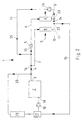
- the cooling and heating circuits shown in Figures 1 to 4 1 for motor vehicles initially have one Cooling water or coolant-cooled internal combustion engine 2 on.
- the coolant circulating in the internal combustion engine 2 is led to a coolant outlet 3, at which a coolant line 4 connects to a coolant heater 5 and to a first heating heat exchanger 6 leads.
- a coolant line 7 which leads to a second Heater heat exchanger 8 leads to the coolant heater 5 and the first heating heat exchanger 6 is connected in parallel.
- the two heating heat exchangers 6, 8 may be the same, i. H. especially the have the same heating efficiency curve.
- the heating air 9 is first through the second heating heat exchanger 8, then through the first heating heat exchanger 6 and from there in headed the passenger compartment.
- a coolant line 11 is connected, in which the coolant outlet 12 of the first heating heat exchanger 6 opens and then into an adjustable, electrically driven auxiliary coolant pump 13 and continues to the coolant line 4, which leads to the internal combustion engine 2 connects to the coolant heater 5.
- this coolant line 4 opens from the auxiliary coolant pump 13 coming coolant line 11 between the branch 14 leading to the second heating heat exchanger 8 and the coolant inlet 15 of the coolant heater 5 a.
- Coolant line 11 is connected to a coolant line 16, which via a thermostat 17 and a coolant pump 18 to coolant inlet 19 of internal combustion engine 2 returns.
- auxiliary coolant pump 13 By a suitably adjusted or regulated Delivery rate of the auxiliary coolant pump 13 is almost a Circulation of part of the coolant via the coolant heating device 5 and the first heating heat exchanger 6 reached. In this way it turns out through the Auxiliary coolant pump 13 conveyed coolant due to the repeated pass through the coolant heater 5 compared to a single pass through the coolant heating device 5 considerably increased temperature one leading to a significant improvement in passenger compartment heating leads.
- the one flowing through the second heating heat exchanger 8 Only a small part of the coolant runs to the auxiliary coolant pump 13, but mostly through the coolant line 16 via the thermostat 17 and the coolant pump 18 back to the internal combustion engine 2. It will be an extensive one Division of the coolant flow into two circuits achieved, without being necessary for complex mechanical means are and without the circuits actually mechanically separated are.
- the flow rate the coolant return to the coolant heating device 5 be adapted to the required conditions, but the flow rate should be at least as high that a coolant flow from the internal combustion engine 2 via the auxiliary coolant pump 13 back to the internal combustion engine 2 is prevented.
- a second one Check valve 25 switched that a coolant flow from the internal combustion engine 2 to the auxiliary coolant pump 13 prevents when the auxiliary coolant pump 13 is completely switched off becomes.
- the auxiliary coolant pump 13 switched off the majority of the first heating heat exchanger flows 6 flowing coolant together with the passing through the second heating heat exchanger 8 Coolant flow back to the internal combustion engine 2. This mode of operation with the auxiliary coolant pump 13 switched off for accelerated warming up of the internal combustion engine 2 or of the lubricant applicable with reduced passenger compartment heating.
- the auxiliary coolant pump 13 has in the idle state in a high flow resistance in both directions takes on the additional function of her check valve 25 from FIG. 2 connected in series.
- the auxiliary coolant pump 13 as a gear pump be trained. Is a greater warm-up of the Internal combustion engine 2 is desired, the throttle valve 27 opened so that the emerging from the internal combustion engine 2 Coolant flow already at branch 14 divides, and the auxiliary coolant pump 13 is switched off.
- the height Flow resistance of the switched off auxiliary coolant pump 13 prevents a coolant flow through the Auxiliary coolant pump 13 leading coolant line 11, and the two emerging from the two heating heat exchangers 6, 8 Coolant flows sweep together through the coolant line 16 back to the internal combustion engine 2 and effect their faster warming up.
- this cooling and heating circuit corresponds to that of Figure 3, wherein a coolant flow to achieve optimum passenger compartment heating from the engine 2 to the coolant heater 5 is interrupted and to achieve one optimal warming of the engine 2 of the coolant flow from the auxiliary coolant pump 13 to the coolant heater 5 interrupted and this with that of the Internal combustion engine 2 coming coolant line 4 connected is.
- Both the throttle valve 27 and the three-way valve 28 can be controlled by an electronic engine control become.
- FIG. 5 shows an embodiment of an inventive Heater heat exchanger 30, the two in a housing 31st summarized heat exchanger cores 32.
- the heat exchanger cores 32 lie side by side and are against each other heat insulated to prevent heat transfer against the flow direction to prevent the heating air 9.
- the two Heat exchanger cores 32 are on two opposite one another Sides of the housing 31 at their ends 33, 34, 35, 36 each connected to a housing opening 37, 38, 39, 40, the housing openings on one side each by a Separating device 41, 42 are separated from one another.
- arrows 43, 44 for the coolant flow give use in a cooling and heating circuit 1 according to Figures 1 to 4 again.
- the two through the Separator 41 separate openings 37, 38 each serve as an inlet for separate coolant flows 43, 44, wherein the coolant flow 44a entering on the right in FIG. 5 the coolant heater 5 and the first heater heat exchanger 6 and the coolant flow 43a on the left in FIG. 5 has passed through the second heating heat exchanger 8.
- the both separated by the separating device 42, in FIG. 5 lower openings 39, 40 each serve as an outlet for separate coolant flows 43, 44, the right emerging Coolant flow 44b entirely or predominantly to the auxiliary coolant pump 13 arrives and the left emerging coolant flow 43b entirely or predominantly to the internal combustion engine 2 returns.
- the first heat exchanger core 32 ' shows a reduced cross section of the connecting pipes on. With the electric auxiliary coolant pump 13 this can be carried out or compensated for and causes less Space requirements and lower material consumption for the additional wiring to the coolant heater 5th
Landscapes
- Engineering & Computer Science (AREA)
- Chemical & Material Sciences (AREA)
- Combustion & Propulsion (AREA)
- Physics & Mathematics (AREA)
- Thermal Sciences (AREA)
- Mechanical Engineering (AREA)
- Air-Conditioning For Vehicles (AREA)
Claims (7)
- Circuit (1) de refroidissement et de chauffage pour véhicules automobiles équipés d'un moteur à combustion interne (2) refroidi par réfrigérant, comprenant :caractérisé en ce que le dispositif (5) de chauffage de réfrigérant est disposé dans la conduite (4) d'apport de réfrigérant menant au premier échangeur thermique (6) de réfrigérant.un premier circuit de réfrigérant, comprenant le moteur à combustion interne (2), une pompe de réfrigérant (18) et un deuxième échangeur thermique (8) de chauffage ;un premier échangeur thermique (6) de chauffage qui, par l'intermédiaire d'une conduite (4) d'apport de réfrigérant, est raccordé au premier circuit de réfrigérant en parallèle avec le deuxième échangeur thermique (8) de chauffage ;un deuxième circuit de réfrigérant, comprenant le premier échangeur thermique (6) de réfrigérant, une pompe auxiliaire réglable (13) de réfrigérant et la conduite (4) d'apport de réfrigérant menant au premier échangeur thermique (6) de réfrigérant ;un dispositif (5) de chauffage de réfrigérant disposé dans le deuxième circuit de réfrigérant ;une conduite de réfrigérant (11) s'étendant à partir de la sortie de réfrigérant (10) du deuxième échangeur thermique (8) de chauffage, conduite (11) à laquelle est d'abord raccordée la conduite de réfrigérant (16) retournant au moteur à combustion interne (2), et conduite (11) dans laquelle débouche ensuite la sortie de réfrigérant (12) du premier échangeur thermique (6) de chauffage, et conduite (11) qui mène ensuite, par l'intermédiaire de la pompe auxiliaire réglable (13) de réfrigérant, à l'entrée de réfrigérant (15) du dispositif (5) de chauffage de réfrigérant ;
- Circuit de refroidissement et de chauffage selon la revendication 1, caractérisé en ce qu'une soupape antiretour (24) est montée dans la conduite de réfrigérant (11) entre le branchement (22) de la conduite de réfrigérant (16) retournant au moteur à combustion interne (2) et l'embouchure (23) de la sortie de réfrigérant (12) du premier échangeur thermique (6) de chauffage, soupape qui empêche un flux de réfrigérant depuis le deuxième échangeur thermique (8) de chauffage vers la pompe auxiliaire (13) de réfrigérant.
- Circuit de refroidissement et de chauffage selon la revendication 1 ou 2, caractérisé en ce qu'une soupape antiretour (25) est montée entre la pompe auxiliaire (13) de réfrigérant et l'entrée de réfrigérant (15) du dispositif (5) de chauffage de réfrigérant, soupape qui empêche, à l'état de repos de la pompe auxiliaire (13) de réfrigérant, un flux de réfrigérant par l'intermédiaire de la pompe auxiliaire (13) de réfrigérant vers les échangeurs thermiques (6, 8) de chauffage ou vers le moteur à combustion interne (2).
- Circuit de refroidissement et de chauffage selon la revendication 1 ou 2, caractérisé en ce qu'on utilise une pompe auxiliaire (13) de réfrigérant qui présente une haute résistance à la circulation à l'état de repos.
- Circuit de refroidissement et de chauffage selon la revendication 4, caractérisé en ce que la conduite de réfrigérant (11) provenant de la pompe auxiliaire (13) de réfrigérant débouche dans la conduite (4) de réfrigérant provenant du moteur à combustion interne (2) entre la dérivation (14) menant au deuxième échangeur thermique (8) de chauffage et l'entrée de réfrigérant (15) du dispositif (5) de chauffage de réfrigérant, et en ce qu'une soupape d'étranglement (27) est montée entre la dérivation précitée (14) et l'embouchure (26).
- Circuit de refroidissement et de chauffage selon la revendication 4, caractérisé en ce qu'une soupape (28) à trois voies est prévue entre la dérivation (14) menant au deuxième échangeur thermique (8) de chauffage et le dispositif (5) de chauffage de réfrigérant, soupape dont la première entrée est reliée à la conduite (4) de réfrigérant provenant du moteur à combustion interne (2), dont la deuxième entrée est reliée à la conduite de réfrigérant (11) provenant de la pompe auxiliaire (13) de réfrigérant, et dont la sortie est reliée à l'entrée de réfrigérant (15) du dispositif (5) de chauffage de réfrigérant.
- Circuit de refroidissement et de chauffage selon la revendication 5 ou 6, caractérisé en ce que les soupapes (27, 28) peuvent être commandées électroniquement
Priority Applications (2)
| Application Number | Priority Date | Filing Date | Title |
|---|---|---|---|
| DE59808921T DE59808921D1 (de) | 1998-12-07 | 1998-12-07 | Kühl- und Heizungskreislauf sowie Wärmetauscher für Kraftfahrzeuge mit zusätzlicher Kühlmittel-Heizeinrichtung |
| EP98123258A EP1008471B1 (fr) | 1998-12-07 | 1998-12-07 | Circulation de refroidissement et de chauffage et échangeur thérmique pour véhicules avec un dispositif de chauffage du liquide de refroidissement |
Applications Claiming Priority (1)
| Application Number | Priority Date | Filing Date | Title |
|---|---|---|---|
| EP98123258A EP1008471B1 (fr) | 1998-12-07 | 1998-12-07 | Circulation de refroidissement et de chauffage et échangeur thérmique pour véhicules avec un dispositif de chauffage du liquide de refroidissement |
Publications (2)
| Publication Number | Publication Date |
|---|---|
| EP1008471A1 EP1008471A1 (fr) | 2000-06-14 |
| EP1008471B1 true EP1008471B1 (fr) | 2003-07-02 |
Family
ID=8233102
Family Applications (1)
| Application Number | Title | Priority Date | Filing Date |
|---|---|---|---|
| EP98123258A Expired - Lifetime EP1008471B1 (fr) | 1998-12-07 | 1998-12-07 | Circulation de refroidissement et de chauffage et échangeur thérmique pour véhicules avec un dispositif de chauffage du liquide de refroidissement |
Country Status (2)
| Country | Link |
|---|---|
| EP (1) | EP1008471B1 (fr) |
| DE (1) | DE59808921D1 (fr) |
Families Citing this family (5)
| Publication number | Priority date | Publication date | Assignee | Title |
|---|---|---|---|---|
| DE102010052019A1 (de) | 2009-11-25 | 2011-06-09 | Denso Corporation, Kariya-City | Klimaanlage für Fahrzeug |
| CN102191991A (zh) * | 2010-03-03 | 2011-09-21 | 株式会社电装 | 用于发动机冷却系统的控制器 |
| JP5533685B2 (ja) | 2011-01-14 | 2014-06-25 | 株式会社デンソー | 車両用空調装置 |
| DE102013006155B4 (de) * | 2013-04-10 | 2022-05-05 | Audi Ag | Verfahren zum Heizen eines Fahrzeuginnenraums eines eine Brennkraftmaschine aufweisenden Fahrzeugs |
| DE102015222806A1 (de) * | 2015-11-19 | 2017-05-24 | Bayerische Motoren Werke Aktiengesellschaft | Wärmesystem und verfahren zur klimatisierung eines fahrzeugs |
Family Cites Families (5)
| Publication number | Priority date | Publication date | Assignee | Title |
|---|---|---|---|---|
| US3540651A (en) * | 1968-10-04 | 1970-11-17 | Stewart Warner Corp | Combustion heater vehicle heating system |
| JPS60148715A (ja) * | 1984-01-12 | 1985-08-06 | Fuji Heavy Ind Ltd | 車両用暖房装置 |
| DE3401207A1 (de) * | 1984-01-14 | 1985-07-25 | Klöckner-Humboldt-Deutz AG, 5000 Köln | Einrichtung zum aufheizen von raumluft |
| FR2615457B1 (fr) * | 1987-05-21 | 1993-06-04 | Valeo | Installation de chauffage pour vehicule automobile comportant un generateur de chaleur |
| DE4022731A1 (de) * | 1990-07-17 | 1992-01-23 | Eberspaecher J | Mit einem heizgeraet versehener kuehlmittelkreislauf eines fahrzeugmotors |
-
1998
- 1998-12-07 DE DE59808921T patent/DE59808921D1/de not_active Expired - Lifetime
- 1998-12-07 EP EP98123258A patent/EP1008471B1/fr not_active Expired - Lifetime
Also Published As
| Publication number | Publication date |
|---|---|
| DE59808921D1 (de) | 2003-08-07 |
| EP1008471A1 (fr) | 2000-06-14 |
Similar Documents
| Publication | Publication Date | Title |
|---|---|---|
| EP0861368B1 (fr) | Circuit de refroidissement d'un moteur a combustion interne ainsi que son mode operatoire | |
| DE19954327B4 (de) | Verfahren und Vorrichtung zum Transport von in einem Kraftfahrzeug entstehender Wärmeenergie | |
| DE102012105644B4 (de) | Wärmetauscher für ein fahrzeug | |
| DE19849492B4 (de) | Steuervorrichtung für einen Kühlkreislauf einer Brennkraftmaschine | |
| EP1319815A2 (fr) | Circuit de refroidissement d'un moteur à combustion interne refroidi par liquide | |
| EP1111214A2 (fr) | Circuit pour refroidissement et chauffage avec deux radiateurs | |
| EP1108572B1 (fr) | Système d'échange de chaleur pour le chauffage d'un véhicule à propulsion hybride | |
| DE3047672A1 (de) | Kuehleinrichtung zur kuehlung einer brennkraftmaschine und der ladeluft | |
| EP3747074B1 (fr) | Système de refroidissement conçu pour un empilement de pile à combustible | |
| DE19741861B4 (de) | Vorrichtung zur Regelung des Kühlwasserkreislaufes für einen Verbrennungsmotor | |
| DE10319762A1 (de) | Kreislauf zur Kühlung von Ladeluft und Verfahren zum Betreiben eines derartigen Kreislaufs | |
| DE10146313A1 (de) | Kühlkreislauf einer flüssigkeitsgekühlten Brennkraftmaschine | |
| EP3325859B1 (fr) | Module de répartition d'un agent de refroidissement pour un circuit de refroidissement | |
| DE19831901A1 (de) | Vorrichtung zum Kühlen eines Motors für ein Kraftfahrzeug | |
| EP1008471B1 (fr) | Circulation de refroidissement et de chauffage et échangeur thérmique pour véhicules avec un dispositif de chauffage du liquide de refroidissement | |
| WO2017005438A1 (fr) | Circuit à fluide de refroidissement pour boîte de vitesses à refroidissement par liquide | |
| DE112018004425T5 (de) | Aktives Aufheizsystem und Aufheizverfahren | |
| DE4131357C1 (en) | IC engine cooling installation with engine-driven pump - has electrically driven second pump with external line contg. two thermostatic valves | |
| DE112014004338T5 (de) | Kühlsystem in einem Fahrzeug | |
| WO2008046490A1 (fr) | Circuit de refroidissement pour moteur à combustion interne | |
| DE102010015106B4 (de) | Kühlmittelkreislauf für eine Brennkraftmaschine eines Kraftfahrzeugs | |
| DE112011104871B4 (de) | Kühlsystem | |
| DE102019119311B4 (de) | Antriebssystem für ein Elektrofahrzeug und Elektrofahrzeug | |
| DE19712479B4 (de) | Kühleinrichtung für den Kraftstoff der Einspritzanlage von Verbrennungsmotoren | |
| DE4139886C2 (de) | Wärmeträgerkreislauf eines Fahrzeuges |
Legal Events
| Date | Code | Title | Description |
|---|---|---|---|
| PUAI | Public reference made under article 153(3) epc to a published international application that has entered the european phase |
Free format text: ORIGINAL CODE: 0009012 |
|
| 17P | Request for examination filed |
Effective date: 19990707 |
|
| AK | Designated contracting states |
Kind code of ref document: A1 Designated state(s): DE FR GB IT SE |
|
| AX | Request for extension of the european patent |
Free format text: AL;LT;LV;MK;RO;SI |
|
| AKX | Designation fees paid |
Free format text: DE FR GB IT SE |
|
| 17Q | First examination report despatched |
Effective date: 20020718 |
|
| GRAH | Despatch of communication of intention to grant a patent |
Free format text: ORIGINAL CODE: EPIDOS IGRA |
|
| GRAH | Despatch of communication of intention to grant a patent |
Free format text: ORIGINAL CODE: EPIDOS IGRA |
|
| GRAA | (expected) grant |
Free format text: ORIGINAL CODE: 0009210 |
|
| AK | Designated contracting states |
Designated state(s): DE FR GB IT SE |
|
| PG25 | Lapsed in a contracting state [announced via postgrant information from national office to epo] |
Ref country code: IT Free format text: LAPSE BECAUSE OF FAILURE TO SUBMIT A TRANSLATION OF THE DESCRIPTION OR TO PAY THE FEE WITHIN THE PRE;WARNING: LAPSES OF ITALIAN PATENTS WITH EFFECTIVE DATE BEFORE 2007 MAY HAVE OCCURRED AT ANY TIME BEFORE 2007. THE CORRECT EFFECTIVE DATE MAY BE DIFFERENT FROM THE ONE RECORDED.SCRIBED TIME-LIMIT Effective date: 20030702 |
|
| REG | Reference to a national code |
Ref country code: GB Ref legal event code: FG4D Free format text: NOT ENGLISH |
|
| REF | Corresponds to: |
Ref document number: 59808921 Country of ref document: DE Date of ref document: 20030807 Kind code of ref document: P |
|
| PG25 | Lapsed in a contracting state [announced via postgrant information from national office to epo] |
Ref country code: SE Free format text: LAPSE BECAUSE OF FAILURE TO SUBMIT A TRANSLATION OF THE DESCRIPTION OR TO PAY THE FEE WITHIN THE PRESCRIBED TIME-LIMIT Effective date: 20031002 |
|
| GBT | Gb: translation of ep patent filed (gb section 77(6)(a)/1977) |
Effective date: 20031106 |
|
| REG | Reference to a national code |
Ref country code: GB Ref legal event code: 732E |
|
| PLBE | No opposition filed within time limit |
Free format text: ORIGINAL CODE: 0009261 |
|
| STAA | Information on the status of an ep patent application or granted ep patent |
Free format text: STATUS: NO OPPOSITION FILED WITHIN TIME LIMIT |
|
| ET | Fr: translation filed | ||
| 26N | No opposition filed |
Effective date: 20040405 |
|
| REG | Reference to a national code |
Ref country code: FR Ref legal event code: TP |
|
| PGFP | Annual fee paid to national office [announced via postgrant information from national office to epo] |
Ref country code: GB Payment date: 20141124 Year of fee payment: 17 |
|
| PGFP | Annual fee paid to national office [announced via postgrant information from national office to epo] |
Ref country code: FR Payment date: 20141124 Year of fee payment: 17 |
|
| PGFP | Annual fee paid to national office [announced via postgrant information from national office to epo] |
Ref country code: DE Payment date: 20141222 Year of fee payment: 17 |
|
| REG | Reference to a national code |
Ref country code: DE Ref legal event code: R082 Ref document number: 59808921 Country of ref document: DE Representative=s name: DOERFLER, THOMAS, DR.-ING., DE |
|
| REG | Reference to a national code |
Ref country code: DE Ref legal event code: R119 Ref document number: 59808921 Country of ref document: DE |
|
| GBPC | Gb: european patent ceased through non-payment of renewal fee |
Effective date: 20151207 |
|
| REG | Reference to a national code |
Ref country code: FR Ref legal event code: ST Effective date: 20160831 |
|
| PG25 | Lapsed in a contracting state [announced via postgrant information from national office to epo] |
Ref country code: GB Free format text: LAPSE BECAUSE OF NON-PAYMENT OF DUE FEES Effective date: 20151207 Ref country code: DE Free format text: LAPSE BECAUSE OF NON-PAYMENT OF DUE FEES Effective date: 20160701 |
|
| PG25 | Lapsed in a contracting state [announced via postgrant information from national office to epo] |
Ref country code: FR Free format text: LAPSE BECAUSE OF NON-PAYMENT OF DUE FEES Effective date: 20151231 |