EP1007838B1 - Dispositif d'aspiration a base de pompe a jet pour reservoir de carburant de vehicules automobiles - Google Patents
Dispositif d'aspiration a base de pompe a jet pour reservoir de carburant de vehicules automobiles Download PDFInfo
- Publication number
- EP1007838B1 EP1007838B1 EP97942078A EP97942078A EP1007838B1 EP 1007838 B1 EP1007838 B1 EP 1007838B1 EP 97942078 A EP97942078 A EP 97942078A EP 97942078 A EP97942078 A EP 97942078A EP 1007838 B1 EP1007838 B1 EP 1007838B1
- Authority
- EP
- European Patent Office
- Prior art keywords
- nozzle
- fact
- flow
- injected
- lips
- Prior art date
- Legal status (The legal status is an assumption and is not a legal conclusion. Google has not performed a legal analysis and makes no representation as to the accuracy of the status listed.)
- Expired - Lifetime
Links
- 239000002828 fuel tank Substances 0.000 title claims description 3
- 230000006698 induction Effects 0.000 title 1
- 239000000446 fuel Substances 0.000 claims description 13
- 230000000694 effects Effects 0.000 claims description 11
- 238000002347 injection Methods 0.000 claims description 8
- 239000007924 injection Substances 0.000 claims description 8
- 239000000463 material Substances 0.000 claims description 8
- 239000000806 elastomer Substances 0.000 claims description 3
- 229920001973 fluoroelastomer Polymers 0.000 claims description 3
- 229920003052 natural elastomer Polymers 0.000 claims description 3
- 229920001194 natural rubber Polymers 0.000 claims description 3
- 244000043261 Hevea brasiliensis Species 0.000 claims description 2
- NBVXSUQYWXRMNV-UHFFFAOYSA-N fluoromethane Chemical compound FC NBVXSUQYWXRMNV-UHFFFAOYSA-N 0.000 claims description 2
- 229920001971 elastomer Polymers 0.000 claims 2
- YCKRFDGAMUMZLT-UHFFFAOYSA-N Fluorine atom Chemical compound [F] YCKRFDGAMUMZLT-UHFFFAOYSA-N 0.000 claims 1
- 229910052731 fluorine Inorganic materials 0.000 claims 1
- 239000011737 fluorine Substances 0.000 claims 1
- 239000013013 elastic material Substances 0.000 description 3
- 230000000750 progressive effect Effects 0.000 description 2
- 238000005086 pumping Methods 0.000 description 2
- 238000011144 upstream manufacturing Methods 0.000 description 2
- 241000907903 Shorea Species 0.000 description 1
- 230000032683 aging Effects 0.000 description 1
- WUKWITHWXAAZEY-UHFFFAOYSA-L calcium difluoride Chemical compound [F-].[F-].[Ca+2] WUKWITHWXAAZEY-UHFFFAOYSA-L 0.000 description 1
- 239000010436 fluorite Substances 0.000 description 1
- 210000000056 organ Anatomy 0.000 description 1
- 238000007789 sealing Methods 0.000 description 1
Images
Classifications
-
- F—MECHANICAL ENGINEERING; LIGHTING; HEATING; WEAPONS; BLASTING
- F04—POSITIVE - DISPLACEMENT MACHINES FOR LIQUIDS; PUMPS FOR LIQUIDS OR ELASTIC FLUIDS
- F04F—PUMPING OF FLUID BY DIRECT CONTACT OF ANOTHER FLUID OR BY USING INERTIA OF FLUID TO BE PUMPED; SIPHONS
- F04F5/00—Jet pumps, i.e. devices in which flow is induced by pressure drop caused by velocity of another fluid flow
- F04F5/44—Component parts, details, or accessories not provided for in, or of interest apart from, groups F04F5/02 - F04F5/42
- F04F5/46—Arrangements of nozzles
- F04F5/461—Adjustable nozzles
-
- F—MECHANICAL ENGINEERING; LIGHTING; HEATING; WEAPONS; BLASTING
- F02—COMBUSTION ENGINES; HOT-GAS OR COMBUSTION-PRODUCT ENGINE PLANTS
- F02M—SUPPLYING COMBUSTION ENGINES IN GENERAL WITH COMBUSTIBLE MIXTURES OR CONSTITUENTS THEREOF
- F02M37/00—Apparatus or systems for feeding liquid fuel from storage containers to carburettors or fuel-injection apparatus; Arrangements for purifying liquid fuel specially adapted for, or arranged on, internal-combustion engines
- F02M37/02—Feeding by means of suction apparatus, e.g. by air flow through carburettors
Definitions
- the present invention relates to the field of suction devices for base of jet or Venturi effect pumps.
- the present invention applies to pumping fuel for vehicles automobiles.
- jet or Venturi effect pumps are generally used to transfer fuel between pockets in multi-pocket tanks, or to transfer fuel from a main tank to a reserve bowl from which the fuel is drawn to be directed to the engine.
- Examples of pump-based fuel suction devices jet or Venturi effect are illustrated in documents DE-A-3915185, DE-A-3612194 or DE-A-2602234.
- Suction devices based on jet or Venturi effect pumps conventionally comprise a conduit which receives an injected flow, provided at its outlet of a first converging nozzle forming opposite a second converging forming a venturi tube which leads to the outlet of the device, to deliver a transferred flow, the main input of the device through which the sucked flow passes being located between the two convergers, i.e. between the nozzle and the tube venturi.
- Document JP-A-2095800 describes a jet pump in which a nozzle is formed of elastic material, fluoroelastomer for example, so that the section of this nozzle adapts to the pressure injected.
- the present invention now aims to improve the suction devices for fuel based on jet pumps or Venturi effect.
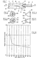
- a jet or effect pump Venturi comprising a body 10.
- the latter carries an injection tube 20 which receives an injected flow Qi.
- This flow injected Qi can come for example from a return of fuel not consumed by the motor, or an output stage of a main pump, for example a electric pump.
- the injection tube 20 is equipped at its outlet (located in a chamber 12 of the body 10) of a convergent 22 forming a nozzle consisting of a nozzle, preferably of elastic material, of cross-section variable opening according to the pressure and flow injected Qi. So according to the invention, the opening of the nozzle 22 automatically increases when the pressure of the injected flow Qi believes.
- the nozzle 22 is coaxial with the chamber 12 formed in the body 10. More specifically, the variable section nozzle 22 is placed opposite a second convergent 14 forming a venturi tube, produced in the body 10. This venturi tube 14 opens into a mixer tube 16 connected to outlet 18 of the device by a diffuser 17 itself consisting for example of a divergent towards exit 18.
- the body 10 also has an inlet 13 which connects the outside of the body 10 to the chamber 12 upstream of the venturi tube 14, that is to say between the outlet of the nozzle 22 and the venturi tube 14.
- the inlet 13 receives a suction flow Qa taken from a reservoir of fuel.
- the output 18 delivers a transferred flow rate Qt equal to the sum of the injected flow Qi and the sucked flow Qa.
- the elastic nozzle 22 must of course be connected so sealed on the outlet of the injection line 20 and also define a sealing with the body 10 so that the suction flow Qa passes entirely through entrance 13.
- the nozzle elastic 22 is attached to the outlet of the injection tube 20.
- the invention is not limited to this embodiment. So, alternatively, we may include integrating the elastic nozzle 22 on the injection tube 20.
- the elastic nozzle 22 must be made of a compatible material with the fuel used.
- it is preferably a compatible material with any type of fuel, petrol or diesel, to allow the realization a universal device (whose elastic characteristics change little as a function of fuel temperature and aging in the fuel).
- the nozzle 22 is thus produced preferably based on natural rubber or elastomer, preferably fluoroelastomer, such as fluorosilicone or fluorocarbon.
- the nozzle 22 can for example be made from the material sold under the VITTON brand.
- the material composing the elastic nozzle 22 preferably has a high fluorite index typically greater than 60% very preferably greater than 65%.
- the material constituting the nozzle elastic 22 preferably has a hardness of the order of 60 shoreA.
- the elastic nozzle of variable opening section 22 preferably consists of several symmetrical elastic lips around an axis O-O centered on the chamber 12 of the body 10. This arrangement makes it possible to maintain an injected jet Qi centered on the chamber 12 and the venturi tube 14 whatever the opening of the elastic nozzle 22.
- the invention is not limited to this provision particular but may have a different number of lips, for example equal to three or even greater than four.
- the elastic nozzle 22 is preferably adapted to withstand injected flows Qi likely to evolve between 0 and 200 l / h, with a back pressure field on the conduit 20 between 0 and 150kPa.
- the elastic nozzle 22 according to the present invention offers many advantages over jet or Venturi effect pumps classics.
- jet pumps are sized for generate a maximum back pressure in relation to the constraints of functioning of the organs upstream of the nozzle receiving the injected flow (petrol version regulator, mechanical diesel pump, ). This against pressure makes it possible to define the minimum tolerable diameter when the injected flow is at its maximum value (zero motor consumption and flow maximum pump for example). For lower injected flows, the jet speed is reduced accordingly and the efficiency of the jet pump is reduced (linear decrease in the Qa / Qi training rate).
- the present invention finds particular interest in the applications with variable injection rates.
Landscapes
- Engineering & Computer Science (AREA)
- Mechanical Engineering (AREA)
- General Engineering & Computer Science (AREA)
- Chemical & Material Sciences (AREA)
- Combustion & Propulsion (AREA)
- Physics & Mathematics (AREA)
- Fluid Mechanics (AREA)
- Jet Pumps And Other Pumps (AREA)
Description
- la figure 1 représente une vue schématique en coupe longitudinale d'un dispositif de pompage conforme à la présente invention,
- la figure 2 représente une vue en bout d'un gicleur élastique conforme à une première variante de l'invention,
- la figure 3 représente une vue latérale de ce gicleur,
- la figure 4 représente une vue en bout d'un gicleur conforme à une seconde variante de l'invention,
- la figure 5 représente une vue latérale de ce gicleur,
- la figure 6 représente des courbes qui illustrent la contre-pression en fonction du débit injecté pour un gicleur classique formé d'un gicleur de section constante et un gicleur formé d'un clapet élastique à section variable conforme à l'invention, dans les mêmes conditions de contre-pression aval,
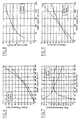
- la figure 7 représente des courbes qui illustrent le taux d'aspiration Qa/Qi en fonction du débit injecté pour les mêmes gicleurs,
- la figure 8 représente des courbes qui illustrent la section de jet, en fonction du débit injecté, pour les mêmes gicleurs,
- la figure 9 représente des courbes qui illustrent la vitesse du jet en fonction du débit injecté pour les mêmes gicleurs, et
- la figure 10 représente une courbe qui illustre le rapport entre le débit aspiré à l'aide d'un gicleur élastique conforme à l'invention et le débit aspiré par un gicleur de section constante classique, en fonction du débit injecté.
- de réguler automatiquement la section du gicleur 22 en fonction du débit injecté Qi,
- une vitesse élevée de jet pour les faibles débits (augmentant l'effet venturi d'aspiration),
- de garder une section de jet réduite pour les débits faibles et donc d'augmenter le taux d'entraínement par rapport à une section fixe constante classique,
- de limiter la contre pression par ouverture progressive de la section avec le débit injecté.
Claims (11)
- Pompe à jet ou effet Venturi pour l'aspiration de carburant dans un réservoir de véhicules automobiles du type comprenant un conduit d'injection (20) recevant un débit injecté muni d'un convergent formant gicleur en sortie, en regard d'un second convergent (14) formant tube venturi relié à la sortie (18) du dispositif délivrant un débit transféré, une entrée (13) par lequel transite un débit aspiré débouchant entre le gicleur et le tube venturi (22, 14), caractérisée par le fait que le gicleur (22) qui reçoit le débit injecté est formé d'une buse composée de plusieurs lèvres en matériau élastique adaptées de sorte que la buse présente une section variable selon la pression et le débit injecté Qi.
- Dispositif selon la revendication 1, caractérisé par le fait que les lèvres élastiques (220, 222 ; 225, 226, 227, 228) sont symétriques par rapport à l'axe de l'entrée du venturi.
- Dispositif selon la revendication 2, caractérisé par le fait que le gicleur (22) comprend deux lèvres (220, 222) diamétralement opposées.
- Dispositif selon la revendication 2, caractérisé par le fait que le gicleur (22) comprend quatre lèvres (225, 226, 227, 228) équi-réparties autour d'un axe.
- Dispositif selon l'une des revendications 1 à 4, caractérisé par le fait que le gicleur (22) est formé d'un caoutchouc naturel ou d'un élastomère.
- Dispositif selon l'une des revendications 1 à 5, caractérisé par le fait que le gicleur (22) est formé d'un fluoroélastomère.
- Dispositif selon l'une des revendications 1 à 6, caractérisé par le fait que le gicleur (22) est formé d'un fluorosilicone ou d'un fluorocarbone.
- Dispositif selon l'une des revendications 1 à 7, caractérisé par le fait que le matériau constituant le gicleur (22) possède un indice de fluorine supérieur à 60%, préférentiellement supérieur à 65%.
- Dispositif selon l'une des revendications 1 à 8, caractérisé par le fait que le matériau constituant le gicleur (22) présente une dureté de l'ordre de 60 shoreA.
- Dispositif selon l'une des revendications 1 à 9, caractérisé par le fait que le gicleur (22) est rapporté sur la sortie d'un tube d'injection (20).
- Réservoir de carburant équipé d'un dispositif d'aspiration conforme à l'une des revendications 1 à 10.
Applications Claiming Priority (3)
| Application Number | Priority Date | Filing Date | Title |
|---|---|---|---|
| FR9611739 | 1996-09-26 | ||
| FR9611739A FR2753748B1 (fr) | 1996-09-26 | 1996-09-26 | Dispositif d'aspiration a base de pompe a jet pour reservoir de carburant de vehicules automobiles |
| PCT/FR1997/001672 WO1998013599A1 (fr) | 1996-09-26 | 1997-09-24 | Dispositif d'aspiration a base de pompe a jet pour reservoir de carburant de vehicules automobiles |
Publications (2)
| Publication Number | Publication Date |
|---|---|
| EP1007838A1 EP1007838A1 (fr) | 2000-06-14 |
| EP1007838B1 true EP1007838B1 (fr) | 2002-06-05 |
Family
ID=9496085
Family Applications (1)
| Application Number | Title | Priority Date | Filing Date |
|---|---|---|---|
| EP97942078A Expired - Lifetime EP1007838B1 (fr) | 1996-09-26 | 1997-09-24 | Dispositif d'aspiration a base de pompe a jet pour reservoir de carburant de vehicules automobiles |
Country Status (4)
| Country | Link |
|---|---|
| EP (1) | EP1007838B1 (fr) |
| DE (1) | DE69713166T2 (fr) |
| FR (1) | FR2753748B1 (fr) |
| WO (1) | WO1998013599A1 (fr) |
Families Citing this family (4)
| Publication number | Priority date | Publication date | Assignee | Title |
|---|---|---|---|---|
| FR2769054B1 (fr) | 1997-10-01 | 2001-12-07 | Marwal Systems | Pompe a jet comprenant un gicleur de section variable |
| DE10119553B4 (de) * | 2001-04-21 | 2005-06-23 | Siemens Ag | Saugstrahlpumpe und Verfahren zur Herstellung einer Düse für eine Saugstrahlpumpe |
| DE10161403B4 (de) | 2001-12-13 | 2007-03-29 | Siemens Ag | Kraftstofffördereinheit |
| DE102015208906A1 (de) * | 2015-05-13 | 2016-11-17 | Mahle International Gmbh | Saugstrahlpumpe mit variabler Düsengeometrie und Kurbelgehäuseentlüftungseinrichtung |
Family Cites Families (6)
| Publication number | Priority date | Publication date | Assignee | Title |
|---|---|---|---|---|
| DE3612195C1 (en) | 1986-04-11 | 1987-07-09 | Daimler Benz Ag | Multiple plug-in connection part, in particular hose coupling |
| JPH0295800A (ja) * | 1988-09-30 | 1990-04-06 | Jidosha Denki Kogyo Co Ltd | 噴流ポンプ |
| DE3915185C1 (fr) | 1989-05-10 | 1990-10-04 | Daimler-Benz Aktiengesellschaft, 7000 Stuttgart, De | |
| DE4123367A1 (de) * | 1991-07-15 | 1993-01-21 | Magenwirth Gmbh Co Gustav | Einrichtung zum foerdern von kraftstoff aus einem behaelter |
| DE4201037B4 (de) * | 1992-01-17 | 2005-10-13 | Bayerische Motoren Werke Ag | Saugstrahlpumpe |
| DE4444855A1 (de) * | 1994-12-16 | 1996-06-20 | Bosch Gmbh Robert | Saugstrahlpumpe |
-
1996
- 1996-09-26 FR FR9611739A patent/FR2753748B1/fr not_active Expired - Fee Related
-
1997
- 1997-09-24 DE DE69713166T patent/DE69713166T2/de not_active Expired - Fee Related
- 1997-09-24 EP EP97942078A patent/EP1007838B1/fr not_active Expired - Lifetime
- 1997-09-24 WO PCT/FR1997/001672 patent/WO1998013599A1/fr not_active Ceased
Also Published As
| Publication number | Publication date |
|---|---|
| WO1998013599A1 (fr) | 1998-04-02 |
| FR2753748B1 (fr) | 1998-12-11 |
| FR2753748A1 (fr) | 1998-03-27 |
| DE69713166T2 (de) | 2002-12-12 |
| EP1007838A1 (fr) | 2000-06-14 |
| DE69713166D1 (de) | 2002-07-11 |
Similar Documents
| Publication | Publication Date | Title |
|---|---|---|
| FR2716936A1 (fr) | Circuit de distribution de carburant pour moteur à combustion interne. | |
| WO1999061777A1 (fr) | Ensemble de puisage de carburant dans un reservoir de vehicule automobile | |
| EP1019627B1 (fr) | Pompe a jet comprenant un gicleur de section variable | |
| WO2011094878A1 (fr) | Pompe doseuse a membrane a usage medical | |
| EP1133632A1 (fr) | Dispositif de puisage de curburant pour reservoir de vehicule automobile | |
| CA2721423C (fr) | Injection d'air dans la veine d'un compresseur de turbomachine | |
| EP1007838A1 (fr) | Dispositif d'aspiration a base de pompe a jet pour reservoir de carburant de vehicules automobiles | |
| FR2818320A1 (fr) | Dispositif de puisage de carburant pour reservoir de vehicule automobile | |
| FR2818321A1 (fr) | Dispositif de puisage de carburant pour reservoir de vehicule automobile | |
| FR2667361A1 (fr) | Collecteur d'amenee de carburant avec une action d'amortissement de vibration, pour une conduite d'amenee de carburant d'un moteur a combustion interne. | |
| FR3051736A1 (fr) | Tete de remplissage pour le remplissage d’un reservoir par un liquide | |
| FR2575518A1 (fr) | Ensemble logement et papillon d'un dispositif de controle de debit de gaz | |
| FR2752309A1 (fr) | Dispositif d'etranglement pour une installation de regulation de pression de l'installation d'alimentation en carburant d'un moteur a combustion interne | |
| EP1215390A1 (fr) | Dispositif d'alimentation en carburant pour moteur à combustion interne et filtre à carburant pour un tel dispositif | |
| FR2533631A1 (fr) | Dispositif de vanne mordulente pour l'admission regulee des gaz de petrole liquides gazeifies | |
| WO2006095111A1 (fr) | Dispositif d'amplification de l'aspiration de gaz recirculant dans le conduit d'admission d'un moteur à combustion interne. | |
| EP2841724B1 (fr) | Systeme de decantation d'huile contenue dans des gaz de carter d'un moteur de vehicule automobile | |
| FR2493404A1 (fr) | Dispositif d'homogeneisation du melange aspire par un moteur a combustion interne | |
| EP0497015A1 (fr) | Dispositif de distribution d'hydrocarbures à récupération de vapeurs | |
| EP2064421A1 (fr) | Agencement pour la depollution d'un moteur thermique comportant un conduit muni d'un element en saillie | |
| EP0169084B1 (fr) | Dispositif de régulation de l'alimentation d'un circuit hydraulique en fluide sous pression | |
| FR2769053A1 (fr) | Pompe a jet comprenant un gicleur de section variable | |
| FR2798163A1 (fr) | Pompe a jet perfectionnee notamment pour dispositif de puisage de carburant | |
| FR2727159A1 (fr) | Systeme d'alimentation en carburant pour moteur a combustion interne, notamment de type diesel | |
| EP0181242A1 (fr) | Régulateur de pression d'essence |
Legal Events
| Date | Code | Title | Description |
|---|---|---|---|
| PUAI | Public reference made under article 153(3) epc to a published international application that has entered the european phase |
Free format text: ORIGINAL CODE: 0009012 |
|
| 17P | Request for examination filed |
Effective date: 19990412 |
|
| AK | Designated contracting states |
Kind code of ref document: A1 Designated state(s): DE FR GB IT |
|
| GRAG | Despatch of communication of intention to grant |
Free format text: ORIGINAL CODE: EPIDOS AGRA |
|
| 17Q | First examination report despatched |
Effective date: 20010531 |
|
| GRAG | Despatch of communication of intention to grant |
Free format text: ORIGINAL CODE: EPIDOS AGRA |
|
| GRAH | Despatch of communication of intention to grant a patent |
Free format text: ORIGINAL CODE: EPIDOS IGRA |
|
| GRAH | Despatch of communication of intention to grant a patent |
Free format text: ORIGINAL CODE: EPIDOS IGRA |
|
| GRAA | (expected) grant |
Free format text: ORIGINAL CODE: 0009210 |
|
| AK | Designated contracting states |
Kind code of ref document: B1 Designated state(s): DE FR GB IT |
|
| REG | Reference to a national code |
Ref country code: GB Ref legal event code: FG4D Free format text: NOT ENGLISH |
|
| REF | Corresponds to: |
Ref document number: 69713166 Country of ref document: DE Date of ref document: 20020711 |
|
| GBT | Gb: translation of ep patent filed (gb section 77(6)(a)/1977) |
Effective date: 20020806 |
|
| PLBE | No opposition filed within time limit |
Free format text: ORIGINAL CODE: 0009261 |
|
| STAA | Information on the status of an ep patent application or granted ep patent |
Free format text: STATUS: NO OPPOSITION FILED WITHIN TIME LIMIT |
|
| 26N | No opposition filed |
Effective date: 20030306 |
|
| PGFP | Annual fee paid to national office [announced via postgrant information from national office to epo] |
Ref country code: FR Payment date: 20050831 Year of fee payment: 9 |
|
| PGFP | Annual fee paid to national office [announced via postgrant information from national office to epo] |
Ref country code: GB Payment date: 20050921 Year of fee payment: 9 |
|
| PG25 | Lapsed in a contracting state [announced via postgrant information from national office to epo] |
Ref country code: IT Free format text: LAPSE BECAUSE OF NON-PAYMENT OF DUE FEES;WARNING: LAPSES OF ITALIAN PATENTS WITH EFFECTIVE DATE BEFORE 2007 MAY HAVE OCCURRED AT ANY TIME BEFORE 2007. THE CORRECT EFFECTIVE DATE MAY BE DIFFERENT FROM THE ONE RECORDED. Effective date: 20050924 |
|
| PGFP | Annual fee paid to national office [announced via postgrant information from national office to epo] |
Ref country code: DE Payment date: 20050929 Year of fee payment: 9 |
|
| PG25 | Lapsed in a contracting state [announced via postgrant information from national office to epo] |
Ref country code: DE Free format text: LAPSE BECAUSE OF NON-PAYMENT OF DUE FEES Effective date: 20070403 |
|
| GBPC | Gb: european patent ceased through non-payment of renewal fee |
Effective date: 20060924 |
|
| REG | Reference to a national code |
Ref country code: FR Ref legal event code: ST Effective date: 20070531 |
|
| PG25 | Lapsed in a contracting state [announced via postgrant information from national office to epo] |
Ref country code: GB Free format text: LAPSE BECAUSE OF NON-PAYMENT OF DUE FEES Effective date: 20060924 |
|
| PG25 | Lapsed in a contracting state [announced via postgrant information from national office to epo] |
Ref country code: FR Free format text: LAPSE BECAUSE OF NON-PAYMENT OF DUE FEES Effective date: 20061002 |