EP1007461B1 - Buckle folder machine with two or three folder pockets - Google Patents
Buckle folder machine with two or three folder pockets Download PDFInfo
- Publication number
- EP1007461B1 EP1007461B1 EP98909278A EP98909278A EP1007461B1 EP 1007461 B1 EP1007461 B1 EP 1007461B1 EP 98909278 A EP98909278 A EP 98909278A EP 98909278 A EP98909278 A EP 98909278A EP 1007461 B1 EP1007461 B1 EP 1007461B1
- Authority
- EP
- European Patent Office
- Prior art keywords
- folder
- folding
- folder block
- machine frame
- block
- Prior art date
- Legal status (The legal status is an assumption and is not a legal conclusion. Google has not performed a legal analysis and makes no representation as to the accuracy of the status listed.)
- Expired - Lifetime
Links
Images


Classifications
-
- B—PERFORMING OPERATIONS; TRANSPORTING
- B65—CONVEYING; PACKING; STORING; HANDLING THIN OR FILAMENTARY MATERIAL
- B65H—HANDLING THIN OR FILAMENTARY MATERIAL, e.g. SHEETS, WEBS, CABLES
- B65H45/00—Folding thin material
- B65H45/12—Folding articles or webs with application of pressure to define or form crease lines
- B65H45/14—Buckling folders
- B65H45/142—Pocket-type folders
- B65H45/144—Pockets or stops therefor
-
- B—PERFORMING OPERATIONS; TRANSPORTING
- B65—CONVEYING; PACKING; STORING; HANDLING THIN OR FILAMENTARY MATERIAL
- B65H—HANDLING THIN OR FILAMENTARY MATERIAL, e.g. SHEETS, WEBS, CABLES
- B65H45/00—Folding thin material
- B65H45/12—Folding articles or webs with application of pressure to define or form crease lines
- B65H45/14—Buckling folders
- B65H45/142—Pocket-type folders
- B65H45/147—Pocket-type folders folding rollers therefor
Definitions
- the invention relates to a compression folder with two or three folding pockets, with several folding rollers, in one folding unit block detachable from the machine frame and with one outside of the folder block arranged drive, the folder block on its one side has a sheet inlet and on the opposite Side has a sheet outlet and where the sheets to the folder block over transport devices fed along an inlet plane in the direction of paper travel and along an outlet plane in the same Direction are transported away.
- the folding pockets are permanently installed in the paper running direction.
- Two fold pocket configurations are possible, namely the first fold pocket at the bottom and the second fold pocket at the top and vice versa in the direction of paper travel.
- the first folding pocket is arranged below or above, there are different folding options. If such folding units with two folding pockets are used on inserting machines or similar machines, the form must have a certain position after leaving the folding unit. If, for example, the inserting machine provides the envelope with the window on top, the form must be folded so that the address behind the folder is on the top, otherwise an additional device for turning the form would be necessary.
- an upsetting folder could be used, which has one folding pocket and one pair of folding rollers more than folds are required in the relevant form, i.e. for folding a form with two folds, an upsetting folder with three folding pockets and for folding a form with three folds , a compression folder with four folding pockets.
- One of the folding pockets can then be switched off by suitable switches and the form can be folded so that the address after the folding unit is either up or down.
- the larger number of folding pockets and folding rollers creates additional costs and sources of error as well as cycle time losses due to the lengthening of the running distance in the folding unit.
- a paper folding machine is also known (DE-PS 517 549) in which one of the folding rollers is movably mounted, so that you can choose with two different other folding rollers can work together and also have a the folding pockets from one machine side to the other is feasible. In this way, one can choose either opposite Produce directional folds, however, lies Sheet outlet depending on the position of the movable folding roller and the convertible folding pocket either on the inlet side of the bend or on the opposite side of the inlet side Page.
- the invention is therefore based on the object Compression folder with two or three folding pockets at the beginning mentioned type to create which is inexpensive is producible and so convertible with little effort is that with him the different mentioned above Folds can be made.
- the Inlet level and the outlet level of the transport devices arranged essentially in a common plane are that the folding rollers and folding pockets in Folding unit block are arranged so that the sheet inlet and the sheet outlet in the respective installation position of the folder in the machine frame in Area of this common level is that all folding rollers in the folder block via coupling gearwheels one end of each folding roller is arranged, are coupled in terms of drive that the Drive is arranged in the machine frame and in the area of the folder block is stored in the machine frame Has drive gear, which is in a first installation position of the folder block with one of the coupling gearwheels combs, and that one of the folding rollers on her the other end carries an output gear, which in a second installation position of the folder block, in which compared to its first installation position by one imaginary running parallel to the direction of the paper Axis rotated through 180 ° inserted into the machine frame is meshing with the drive gear.
- the invention is therefore based on the idea of installing one and the same folding block in the machine frame in two different installation positions rotated by 180 ° with respect to one another.
- the first folding pocket below and the second folding pocket above and in a second installation position of the folder block are arranged, so that depending on the installation position of the folder block in the machine frame, different folds of the paper sheet or form can be generated.
- the sheet infeed and sheet outfeed of the folder block are arranged in the same common plane as the entry level and the exit level, regardless of the respective installation position, it is not necessary to adjust the transport devices upstream and downstream of the upsetting folder when the folder block is 180 ° in both of them twisted installation positions in the machine frame.
- the only changeover measure is to detach the folder block from the machine frame, turn it through 180 °, reinsert it into the machine frame and screw it there.
- the drive gear mounted in the machine frame depending on the installation position of the folder block, meshes with either one of the coupling gears or with the driven gear arranged on the other side of the folder block, no further assembly work is required to connect the drive to one of the folding rollers.
- the output gear can be assigned to one of these four folds in such a way that reversing the direction of rotation of the drive motor is not necessary in order to drive the folding rollers in the correct direction of rotation regardless of the respective installation position of the folder block.
- this Machine frame positioning devices on, by means of which the folder unit in its two installation positions can be positioned in relation to the machine frame is that the sheet inlet and outlet are in the common plane and the drive gear alternately with one of the coupling gears or the output gear meshes.
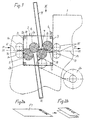
- the upsetting folder has a machine frame 1 and one of this detachable folder block 2.
- Positioning device provided in the form of guides 3, into which the folder block can be inserted from above is.
- screws 4 can be provided.
- the folder block 2 has lateral bearing plates 2a on, which are connected to each other via cross struts 2b are.
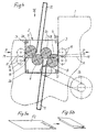
- the one shown in FIGS. 7 and 8 The embodiment is still a folding roller 9 provided.
- the one shown in Figures 1-6 Embodiment has the folder block 2 two Folding pockets 11, 12, while in the case of FIG and 8 shown embodiment, a third Folding pocket 13 is present.
- the folder block In front of the folder block is one through two transport rollers 14 for example indicated transport device provided with the the sheets of paper to be folded, e.g. printed forms F1 or F2 (see Figures 2a and 5a), the folder block are fed along an inlet plane E. Behind the folder unit 2 is a further transport device, which is indicated by rollers 15, provided with which the folded forms along one Outlet level A can be transported further.
- the entry level E and outlet level A are essentially in a common plane M-M arranged.
- the folding rollers 5 - 8 or 5 - 9 and the folding pockets 11, 12 or 11 - 13 are arranged in the folder 2 so that also its sheet inlet 16 and its sheet outlet 17 in the respective installation position of the folder block 2 in the machine frame in the area of this common level M-M lie. At sheet inlet 16 or Sheet outlet 17 are also provided baffles 18, 19.
- the direction of paper travel is indicated by the arrows P indicated.
- the folding roller 8 has an output gear at its other end 26, which is in the second installation position of the folder block 2, as shown in Figures 4 and 6 is engaged in the drive gear 25.
- the folding rollers without changing the direction of rotation of the drive motor 24 is turned over, according to Figure 4 driven in the direction indicated by arrows.
- the person skilled in the art can readily do that Find out the folding roller that he the output gear 26th must assign so that it is in both installation positions of the Folder the direction of rotation of the drive motor 24 can maintain.
- the output gear of the folding roller 6 be assigned when the drive gear 25 is arranged so that it is in the first installation position meshes with the coupling gear 22 and in the second Installation position of the folder block 2 with the then the output gear assigned to the folding roller 6.
- the folder block an imaginary one that runs across the common plane Rotate the axis by 180 ° to get it from its one installation position in its other installation position.
- the output gear would have to be another Folding roller can be assigned.
Landscapes
- Folding Of Thin Sheet-Like Materials, Special Discharging Devices, And Others (AREA)
Description
Die Erfindung betrifft ein Stauchfalzwerk mit zwei oder drei Falztaschen, mit mehreren Falzwalzen, die in einem vom Maschinengestell lösbaren Falzwerksblock gelagert sind, und mit einem außerhalb des Falzwerksblockes angeordneten Antrieb, wobei der Falzwerksblock an seiner einen Seite einen Bogeneinlauf und an seiner gegenüberliegenden Seite einen Bogenauslauf aufweist und wobei die Bögen dem Falzwerksblock über Transporteinrichtungen entlang einer Einlaufebene in Papierlaufrichtung zugeführt und entlang einer Auslaufebene in der gleichen Richtung abtransportiert werden.The invention relates to a compression folder with two or three folding pockets, with several folding rollers, in one folding unit block detachable from the machine frame and with one outside of the folder block arranged drive, the folder block on its one side has a sheet inlet and on the opposite Side has a sheet outlet and where the sheets to the folder block over transport devices fed along an inlet plane in the direction of paper travel and along an outlet plane in the same Direction are transported away.
Bei den üblichen Stauchfalzwerken mit zwei Falztaschen
sind die Falztaschen in Papierlaufrichtung fest eingebaut.
Dabei sind zwei Anordnungen der Falztaschen
möglich, nämlich in Papierlaufrichtung die erste Falztasche
unten und die zweite Falztasche oben bzw. umgekehrt.
Je nachdem ob die erste Falztasche unten oder
oben angeordnet ist, ergeben sich unterschiedliche
Falzmöglichkeiten. Werden solche Falzwerke mit zwei
Falztaschen an Kuvertiermaschinen oder ähnlichen
Maschinen eingesetzt, so muß das Formular nach Verlassen
des Falzwerkes eine bestimmte Lage aufweisen.
Stellt z.B. die Kuvertiermaschine das Kuvert mit oben
liegendem Fenster zur Verfügung, so muß das Formular
so gefalzt werden, daß die Anschrift hinter dem Falzwerk
oben liegt, da sonst eine zusätzliche Vorrichtung
zum Wenden des Formulars notwendig wäre. Zur Lösung
dieses Problems könnte zwar ein Stauchfalzwerk verwendet
werden, welches eine Falztasche und ein Falzwalzenpaar
mehr aufweist als Falzungen in dem betreffenden
Formular erforderlich sind, also zum Falzen eines
Formulars mit zwei Falzen, ein Stauchfalzwerk mit drei
Falztaschen und zum Falzen eines Formulars mit drei
Falzen, ein Stauchfalzwerk mit vier Falztaschen.
Durch geeignete Weichen kann dann jeweils eine der
Falztaschen ausgeschaltet und das Formular so gefaltet
werden, daß die Anschrift nach dem Falzwerk wahlweise
oben oder unten liegt. Durch die größere Anzahl von Falztaschen
und Falzwalzen entstehen jedoch zusätzliche
Kosten und Fehlerquellen sowie außerdem Taktzeitverluste
durch Laufstreckenverlängerung im Falzwerk.In the usual upsetting folders with two folding pockets, the folding pockets are permanently installed in the paper running direction. Two fold pocket configurations are possible, namely the first fold pocket at the bottom and the second fold pocket at the top and vice versa in the direction of paper travel. Depending on whether the first folding pocket is arranged below or above, there are different folding options. If such folding units with two folding pockets are used on inserting machines or similar machines, the form must have a certain position after leaving the folding unit. If, for example, the inserting machine provides the envelope with the window on top, the form must be folded so that the address behind the folder is on the top, otherwise an additional device for turning the form would be necessary. To solve this problem, an upsetting folder could be used, which has one folding pocket and one pair of folding rollers more than folds are required in the relevant form, i.e. for folding a form with two folds, an upsetting folder with three folding pockets and for folding a form with three folds , a compression folder with four folding pockets.
One of the folding pockets can then be switched off by suitable switches and the form can be folded so that the address after the folding unit is either up or down. However, the larger number of folding pockets and folding rollers creates additional costs and sources of error as well as cycle time losses due to the lengthening of the running distance in the folding unit.
Bei einem bekannten Stauchfalzwerk der eingangs erwähnten Art (DE 24 59 294 C2, Figur 3) besteht der Falzwerksblock aus einem Antriebsblock und einem auf diesen aufgesetzten und auswechselbar befestigten, die Falzwalzen und die Falztaschen aufnehmenden Falzwerkskopf. Der Bogeneinlauf sowie der Bogenauslauf sind im Falzwerkskopf, ebenso wie die Einlauf- und die Auslaufebene, in unterschiedlicher Höhe angeordnet. Der Falzuerkskopf kann gegen andere Falzwerksköpfe mit unterschiedlichem Aufbau und unterschiedlicher Ausstattung ausgewechselt werden, so daß es hier möglich wäre, einen Falzwerkskopf, dessen erste Falztasche unten liegt, gegen einen anderen mit oben liegender erster Falztasche zu ersetzen. Es werden jedoch dann in jedem Fall zwei unterschiedliche Falzwerksköpfe benötigt, wodurch sich die Herstellungskosten und Wartungskosten des Stauchfalzwerkes erhöhen und man außerdem Platz für die Lagerung des nicht benützten Falzwerkskopfes schaffen müßte.In a known upset folder of the type mentioned Art (DE 24 59 294 C2, Figure 3) there is the folder block from a drive block and one on it attached and interchangeably fastened, the folding rollers and the folding head accommodating the folding pockets. The sheet inlet and the sheet outlet are in the folder head, as well as the entry and exit levels, arranged at different heights. The Falzuerkskopf can against other folder heads with different Structure and different equipment replaced so that it would be possible to have a folder head, whose first folding pocket is at the bottom, against one to replace another with the first folding pocket on top. However, there will be two different ones in each case Folding head needed, which increases the manufacturing costs and increase the maintenance costs of the upset folder and you also have space for storing the unused Folding head would have to create.
Ferner ist eine Papierfalzmaschine bekannt (DE-PS 517 549) bei der eine der Falzwalzen beweglich gelagert ist, so daß sie wahlweise mit zwei verschiedenen anderen Falzwalzen zusammenarbeiten kann und bei der außerdem eine der Falztaschen von der einen Maschinenseite zur anderen umsetzbar ist. Hierdurch kann man zwar wahlweise entgegengesetzt gerichtete Falze herstellen, jedoch liegt der Bogenauslauf je nach Stellung der beweglichen Falzwalze und der umsetzbaren Falztasche entweder auf der Einlaufseite des Bogens oder an der der Einlaufseite gegenüberliegenden Seite. Dies hat jedoch zur Folge, daß die Transporteinrichtung, mit der der gefaltete Bogen wegtransportiert wird, je nach Falzrichtung an unterschiedlichen Seiten des Stauchfalzwerks angeordnet sein müßte, was in der Praxis erhebliche Umbauarbeiten erfordern würde, oder überhaupt nicht möglich wäre, weil die verschiedenen Arbeits- und Förderaggregate, welche dem Stauchfalzwerk nachgeschaltet sind, nicht einfach aus ihrer ursprünglichen Anordnung in eine entgegengesetzt gerichtete gebracht werden können.A paper folding machine is also known (DE-PS 517 549) in which one of the folding rollers is movably mounted, so that you can choose with two different other folding rollers can work together and also have a the folding pockets from one machine side to the other is feasible. In this way, one can choose either opposite Produce directional folds, however, lies Sheet outlet depending on the position of the movable folding roller and the convertible folding pocket either on the inlet side of the bend or on the opposite side of the inlet side Page. However, this has the consequence that the Transport device with which the folded sheet is transported away will vary depending on the direction of the fold Sides of the upset folder should be arranged, which in practice require considerable renovation work would, or would not be possible at all, because of the different Working and conveying units, which the Upsetting folding unit are not simply off their original arrangement in an opposite can be brought directed.
Der Erfindung liegt daher die Aufgabe zugrunde, ein Stauchfalzwerk mit zwei oder drei Falztaschen der eingangs erwähnten Art zu schaffen, welches kostengünstig herstellbar ist und mit geringem Arbeitsaufwand so umstellbar ist, daß mit ihm die eingangs erwähnten unterschiedlichen Falzungen durchgeführt werden können.The invention is therefore based on the object Compression folder with two or three folding pockets at the beginning mentioned type to create which is inexpensive is producible and so convertible with little effort is that with him the different mentioned above Folds can be made.
Dies wird nach der Erfindung dadurch erreicht, daß die Einlaufebene und die Auslaufebene der Transporteinrichtungen im wesentlichen in einer gemeinsamen Ebene angeordnet sind, daß die Falzwalzen und Falztaschen im Falzwerksblock so angeordnet sind, daß auch der Bogeneinlauf und der Bogenauslauf in der jeweiligen Einbaustellung des Falzwerksblockes im Maschinengestell im Bereich dieser gemeinsamen Ebene liegen, daß alle Falzwalzen im Falzwerksblock über Koppelzahnräder, die an jeweils einem Ende jeder Falzwalze angeordnet sind, antriebsmäßig miteinander gekoppelt sind, daß der Antrieb im Maschinengestell angeordnet ist und im Bereich des Falzwerksblockes ein im Maschinengestell gelagertes Antriebszahnrad aufweist, welches in einer ersten Einbaustellung des Falzwerksblockes mit einem der Koppelzahnräder kämmt, und daß eine der Falzwalzen an ihrem anderen Ende ein Abtriebszahnrad trägt, das in einer zweiten Einbaustellung des Falzwerksblockes, bei welcher dieser gegenüber seiner ersten Einbaustellung um eine parallel zur Papierlaufrichtung verlaufende, gedachte Achse um 180° gedreht in das Maschinengestell eingesetzt ist, mit dem Antriebszahnrad kämmt.This is achieved according to the invention in that the Inlet level and the outlet level of the transport devices arranged essentially in a common plane are that the folding rollers and folding pockets in Folding unit block are arranged so that the sheet inlet and the sheet outlet in the respective installation position of the folder in the machine frame in Area of this common level is that all folding rollers in the folder block via coupling gearwheels one end of each folding roller is arranged, are coupled in terms of drive that the Drive is arranged in the machine frame and in the area of the folder block is stored in the machine frame Has drive gear, which is in a first installation position of the folder block with one of the coupling gearwheels combs, and that one of the folding rollers on her the other end carries an output gear, which in a second installation position of the folder block, in which compared to its first installation position by one imaginary running parallel to the direction of the paper Axis rotated through 180 ° inserted into the machine frame is meshing with the drive gear.
Die Erfindung geht also von dem Gedanken aus, ein und
denselben Falzuerksblock in zwei verschiedenen, um 180°
zueinander gedrehten Einbaustellungen in das Maschinengestell
einzubauen. Hierdurch ist in einer ersten Einbaustellung
in Papierlaufrichtung gesehen die erste
Falztasche unten und die zweite Falztasche oben und
in einer zweiten Einbaustellung des Falzwerksblockes die
erste Falztasche oben und die zweite Falztasche unten
angeordnet, wodurch je nach Einbaustellung des Falzwerksblockes
im Maschinengestell unterschiedliche
Faltungen des Papierbogens oder Formulars erzeugt
werden können. Da jedoch der Bogeneinlauf und Bogenauslauf
des Falzwerksblockes unabhängig von der jeweiligen
Einbaustellung in der gleichen gemeinsamen Ebene angeordnet
sind wie die Einlaufebene und die Auslaufebene,
ist es nicht erforderlich, die dem Stauchfalzwerk vorund
nachgeschalteten Transporteinrichtungen zu verstellen,
wenn der Falzwerksblock in seinen beiden um 180°
verdrehten Einbaustellungen in das Maschinengestell
eingesetzt wird. Die einzige Umstellmaßnahme besteht
darin, den Falzwerksblock vom Maschinengestell zu lösen,
um 180° zu drehen, wieder in das Maschinengestell einzusetzen
und dort festzuschrauben. Da das im Maschinengestell
gelagerte Antriebszahnrad je nach Einbaustellung
des Falzwerksblockes entweder mit einem der Koppelzahnräder
oder mit dem an der anderen Seite des Falzwerksblockes
angeordneten Abtriebszahnrad kämmt, sind
auch keine weiteren Montagearbeiten erforderlich, um
den Antrieb mit einer der Falzwalzen zu verbinden.
Da bei einem Stauchfalzwerk mit zwei Taschen vier Falzwalzen
vorhanden sind, kann man das Abtriebszahnrad
einer dieser vier Falzfalzen so zuordnen, daß eine
Drehrichtungsumkehr des Antriebsmotors nicht erforderlich
ist, um die Falzwalzen unabhängig von der jeweiligen
Einbaustellung des Falzwerksblockes in der
richtigen Drehrichtung anzutreiben.The invention is therefore based on the idea of installing one and the same folding block in the machine frame in two different installation positions rotated by 180 ° with respect to one another. As a result, in a first installation position in the direction of paper travel, the first folding pocket below and the second folding pocket above and in a second installation position of the folder block the first folding pocket above and the second folding pocket below are arranged, so that depending on the installation position of the folder block in the machine frame, different folds of the paper sheet or form can be generated. However, since the sheet infeed and sheet outfeed of the folder block are arranged in the same common plane as the entry level and the exit level, regardless of the respective installation position, it is not necessary to adjust the transport devices upstream and downstream of the upsetting folder when the folder block is 180 ° in both of them twisted installation positions in the machine frame. The only changeover measure is to detach the folder block from the machine frame, turn it through 180 °, reinsert it into the machine frame and screw it there. Since the drive gear mounted in the machine frame, depending on the installation position of the folder block, meshes with either one of the coupling gears or with the driven gear arranged on the other side of the folder block, no further assembly work is required to connect the drive to one of the folding rollers.
Since there are four folding rollers in an upset folder with two pockets, the output gear can be assigned to one of these four folds in such a way that reversing the direction of rotation of the drive motor is not necessary in order to drive the folding rollers in the correct direction of rotation regardless of the respective installation position of the folder block.
In weiterer Ausgestaltung der Erfindung weist das Maschinengestell Positioniereinrichtungen auf, mittels denen der Falzwerksblock in seinen beiden Einbaustellungen so gegenüber dem Maschinengestell positionierbar ist, daß Bogeneinlauf und Bogenauslauf in der gemeinsamen Ebene liegen und das Antriebszahnrad wechselweise mit dem einen der Koppelzahnräder oder dem Abtriebszahnrad kämmt. Durch eine derartige Positioniereinrichtung, die durch ein geeignetes Führungssystem gebildet sein kann, kann die erforderliche Umstellzeit wesentlich verkürzt werden, denn es ist dann zum Umstellen des Falzwerksblockes aus seiner einen Einbaustellung in seine andere Einbaustellung nur noch das Lösen von einigen wenigen Halteschrauben, das Herausnehmen des Falzwerksblockes aus der Positioniereinrichtung, das Drehen des Falzuerksblockes um 180°, das Wiedereinsetzen desselben in die Positioniereinrichtungen und das Festziehen der Halteschrauben erforderlich. Weitere Umstellungen, wie das Anpassen an die Transporteinrichtungen, das Verbinden mit der Antriebseinrichtung, der Anschluß an Sicherheitsschalter und dgl. sind nicht erforderlich.In a further embodiment of the invention, this Machine frame positioning devices on, by means of which the folder unit in its two installation positions can be positioned in relation to the machine frame is that the sheet inlet and outlet are in the common plane and the drive gear alternately with one of the coupling gears or the output gear meshes. By such Positioning device by a suitable Management system can be formed, the required Changeover time can be significantly reduced because of it is then to move the folder block from his one mounting position in its other mounting position just loosening a few retaining screws, removing the folder from the positioning device, turning the folding block by 180 °, reinserting it into the positioning devices and tightening the retaining screws required. Other changes like that Adapt to the transport equipment, the connection with the drive device, connection to safety switch and the like are not required.
Die Erfindung wird in folgendem, anhand von in der Zeichnung dargestellten Ausführungsbeispielen näher erläutert. Es zeigen:
Figur 1- einen Längsschnitt des Stauchfalzwerkes in schematischer Darstellung mit dem Falzwerksblock in einer ersten Einbaustellung,
Figur 2a und 2b- die mit dieser Einbaustellung erreichbare Verarbeitungsmöglichkeit eines Formulars,
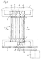
Figur 3- eine Draufsicht in Richtung III der
Figur 1 unter Weglassung der oberen Falztasche, - Figur 4
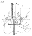
- einen Längsschnitt mit einer zueiten Einbaustellung des Falzuerksblockes,
- Figur 5a und 5b
- mit dieser Einbaustellung erreichbare Verarbeitungsmöglichkeit eines Formulars,
Figur 6- eine Draufsicht in Richtung VI der Figur 4 unter Weglassung der oberen Falztasche,
Figur 7 und 8- Längsschnitte eines zweiten Ausführungsbeispieles eines Stauchfalzwerkes mit drei Falztaschen und zwei verschiedenen Einbaustellungen des Falzwerksblockes.
- Figure 1
- 2 shows a longitudinal section of the upsetting folder in a schematic representation with the folder block in a first installation position,
- Figure 2a and 2b
- the processing possibility of a form that can be achieved with this installation position,
- Figure 3
- 2 shows a top view in the direction III of FIG. 1 with the upper folding pocket omitted,
- Figure 4
- a longitudinal section with a side installation position of the Falzeserksblock,
- Figure 5a and 5b
- With this installation position, a form can be processed,
- Figure 6
- 3 shows a top view in the direction VI of FIG. 4 with the upper folding pocket omitted,
- Figures 7 and 8
- Longitudinal sections of a second embodiment of an upsetting folder with three folding pockets and two different installation positions of the folder block.
Das Stauchfalzwerk weist ein Maschinengestell 1 und
einen von diesem lösbaren Falzwerksblock 2 auf. Zur
Halterung und Positionierung des Falzwerksblocks 2
gegenüber dem Maschinengestell ist zweckmäßig eine
Positioniereinrichtung in Form von Führungen 3 vorgesehen,
in welche der Falzwerksblock von oben einschiebbar
ist. Zur Fixierung des Falzwerksblockes 2 im
Maschinengestell 1 können Schrauben 4 vorgesehen sein.
Der Falzwerksblock 2 weist seitliche Lagerplatten 2a
auf, die über Querstreben 2b miteinander verbunden
sind. In dem Falzwerksblock sind mehrere Falzwalzen
5 - 8 drehbar gelagert. Bei dem in Figur 7 und 8 dargestellten
Ausführungsbeispiel ist noch eine Falzwalze
9 vorgesehen. Bei der in Figur 1 - 6 dargestellten
Ausführungsform weist der Falzwerksblock 2 zwei
Falztaschen 11, 12 auf, während bei der in Figur 7
und 8 dargestellten Ausführungsform noch eine dritte
Falztasche 13 vorhanden ist. Vor dem Falzwerksblock
ist ein durch zwei Transportwalzen 14 beispielsweise
angedeutete Transporteinrichtung vorgesehen, mit der
die zu faltenden Papierbögen, z.B. bedruckte Formulare
F1 bzw. F2 (siehe Figur 2a und 5a), dem Falzwerksblock
entlang einer Einlaufebene E zugeführt werden. Hinter
dem Falzwerksblock 2 ist eine weitere Transporteinrichtung,
die durch Walzen 15 angedeutet ist, vorgesehen,
mit der die gefalteten Formulare entlang einer
Auslaufebene A weitertransportiert werden. Die Einlaufebene
E und Auslaufebene A sind im wesentlichen in
einer gemeinsamen Ebene M-M angeordnet. Die Falzwalzen
5 - 8 bzw. 5 - 9 und die Falztaschen 11, 12 bzw.
11 - 13 sind so im Falzwerksblock 2 angeordnet, daß
auch dessen Bogeneinlauf 16 und dessen Bogenauslauf
17 in der jeweiligen Einbaustellung des Falzwerksblockes
2 im Maschinengestell im Bereich dieser
gemeinsamen Ebene M-M liegen. Am Bogeneinlauf 16 bzw.
Bogenauslauf 17 sind ferner Leitbleche 18, 19 vorgesehen.
Die Papierlaufrichtung ist mit den Pfeilen P
angedeutet. The upsetting folder has a
Aus Figur 3 und 6 ist zu entnehmen, daß an jeweils einem
Ende jeder Falzwalze 5 - 8 ein Koppelzahnrad 20 - 23
angeordnet ist. Die Koppelzahnräder 20 - 23 kämmen miteinander,
wodurch alle vier Falzwalzen 5 - 8 antriebsmäßig
miteinander verbunden sind. Das gleiche gilt
auch bezüglich der weiteren Falzwalzen 9, 10 bei dem
in Figur 7 und 8 dargestellten Ausführungsbeispiel.From Figures 3 and 6 it can be seen that one at a time
A coupling gear 20 - 23 at the end of each folding roller 5 - 8
is arranged. The coupling gears 20-23 mesh with one another,
which drives all four folding rollers 5 - 8
are interconnected. The same goes for
also with respect to the
In dem Maschinengestell 1 ist ferner ein Antriebsmotor
24 angeordnet, der ein im Maschinengestell 1 gelagertes
Antriebszahnrad 25 antreibt. In der ersten, in
Figur 1 und 3 dargestellten Einbaustellung des Falzwerksblockes
2 kämmt dieses Antriebszahnrad 25 mit
einem der Koppelzahnräder, nämlich dem Koppelzahnrad
22, welches der Falzwalze 7 zugeordnet ist. Hierdurch
werden die Falzwalzen 5 - 8 in der in Figur 1 mit
Pfeilen angedeuteten Drehrichtung angetrieben.In the
Die Falzwalze 8 weist an ihrem anderen Ende ein Abtriebszahnrad
26 auf, welches in der zweiten Einbaustellung
des Falzwerksblockes 2, wie es in Figur 4 und 6 dargestellt
ist, in das Antriebszahnrad 25 eingreift.
Hierdurch werden die Falzwalzen, ohne daß die Drehrichtung
des Antriebsmotors 24 umgedreht wird, gemäß
Figur 4 in der mit Pfeilen angedeuteten Richtung angetrieben.
Der Fachmann kann ohne weiteres diejenige
Falzwalze herausfinden, der er das Abtriebszahnrad 26
zuordnen muß, damit er in beiden Einbaustellungen des
Falzwerksblockes die Drehrichtung des Antriebsmotors
24 beibehalten kann. So könnte bei dem beschriebenen
Ausführungsbeispiel das Abtriebszahnrad auch der Falzwalze
6 zugeordnet sein, wenn das Antriebszahnrad 25
so angeordnet wird, daß es in der ersten Einbaustellung
mit dem Koppelzahnrad 22 kämmt und in der zweiten
Einbaustellung des Falzwerksblockes 2 mit dem dann
der Falzwalze 6 zugeordneten Abtriebszahnrad. The
Anhand der Figuren 2a und 2b ist dargestellt, wie ein
Formular F1, bei dem die Anschrift oben angeordnet
ist, mittels des erfindungsgemäßen Stauchfalzwerkes
so gefaltet werden kann, daß gemäß Figur 2b bei dem
gefalteten Formular die Anschrift ebenfalls oben ist.
Zu diesem Zweck ist der Falzwerksblock 2 in seiner
ersten, in Figur 1 und 3 dargestellten Einbaustellung
im Maschinengestell 1 montiert.With the help of Figures 2a and 2b it is shown how a
Form F1, with the address arranged above
is, by means of the upset folding unit according to the invention
can be folded in such a way that according to FIG
folded form the address is also above.
For this purpose the
Soll hingegen ein Formular F2 gemäß Figur 5a mit nach
unten gerichteter Anschrift gefaltet werden, dann
werden die Halteschrauben 4 gelöst und der Falzwerksblock
nach oben aus den Führungen 3 des Maschinengestells
1 herausgezogen. Er wird dann um eine parallel
zur Papierlaufrichtung P verlaufende, gedachte Achse
um 180° gedreht, wie es in Figur 3 mit dem Pfeil D
angedeutet ist. Nach dem Drehen um 180° wird der
Falzwerksblock 2 wieder in die Führungen 3 eingeschoben
und die Halteschrauben 4 werden festgezogen.
Damit ist die gesamte Umstellarbeit beendet.In contrast, a form F2 according to FIG
address below, then
the retaining screws 4 are loosened and the folder block
upwards from the
Wie man anhand der Figur 4 erkennen kann, ist nunmehr
die in Papierlaufrichtung P erste Falztasche 12 des
Falzwerksblockes 2 nach oben gerichtet und die zweite
Falztasche 11 nach unten. Der zwischen der Falzwalze
5 und dem Leitblech 18 gebildete Bogeneinlauf 16 und
auch der zwischen der Falzwalze 8 und dem Leitblech
19 gebildete Bogenauslauf 17 liegen auch in der um
180° gedrehten Stellung des Falzwerksblockes 2 im
Bereich der gemeinsamen Ebene M-M. Die von der
Transporteinrichtung 14 entlang der Einlaufebene E
zugeführten Papierbögen oder Formulare können somit
auch in der zweiten Einbaustellung des Falzwerksblockes
2 in dessen Bogeneinlauf 16 gelangen, ohne daß eine
Höhenverstellung der Transporteinrichtung 14 erforderlich
wäre. Das gleiche gilt auch bezüglich der
Transporteinrichtung 15, welche die aus dem Bogenauslauf
17 austretenden, gefalteten Papierbögen oder
Formulare in Papierlaufrichtung P weitertransportiert.
Mit dem in der zweiten Einbaustellung im Maschinengestell
1 montierten Falzwerksblock können nun gemäß
Figur 5a und 5b Papierbögen oder Formulare F2, bei
denen gemäß Figur 5a die Anschrift nach unten gerichtet
ist, so gefaltet werden, daß die Anschrift
auch nach dem Falten gemäß Figur 5b im gefalteten
Bogen nach unten gerichtet ist.As can be seen from FIG. 4, is now
the
Vorstehende Beschreibung trifft sinngemäß auch auf das
in Figur 7 und 8 dargestellte Stauchfalzwerk, welches
mit drei Falztaschen 11, 12, 13 versehen ist, zu, so
daß sich eine nochmalige Beschreibung erübrigt. Mit
dem in Figur 7 und 8 dargestellten Stauchfalzwerk
können Papierbögen oder Formulare mit drei Faltungen
versehen werden, wobei dann je nach Einbaustellung
des Falzwerksblockes die Anschrift oder ein sonstiger
Aufdruck auch nach dem Falten zu der gleichen Seite
gerichtet ist wie vor dem Falten.The above description also applies to that
in Figure 7 and 8 upsetting folder, which
is provided with three
Gegebenenfalls könnte man den Falzwerksblock auch um eine quer zur gemeinsamen Ebene verlaufende, gedachte Achse um 180° drehen, um ihn von seiner einen Einbaustellung in seine andere Einbaustellung zu bringen. Allerdings müßte dann das Abtriebszahnrad einer anderen Falzwalze zugeordnet werden.If necessary, you could also order the folder block an imaginary one that runs across the common plane Rotate the axis by 180 ° to get it from its one installation position in its other installation position. However, the output gear would have to be another Folding roller can be assigned.
Claims (2)
- A buckle folder with two or three folding plates (11, 12, 13), with several folding rollers mounted in a folder block (2) which is detachable from the machine frame, and with a drive mechanism (24) arranged outside the folder block, the folder block having a sheet input (16) on one of its sides and a sheet output (17) on its opposite side and the sheets being fed to the folder block via transport devices along an input plane (E) in the direction of travel (P) of the paper and delivered along an output plane (A) in the same direction, characterised in that the input plane (E) and the output plane (A) of the transport devices (14, 15) are arranged substantially in a common plane (M-M), in that the folding rollers (5 - 9) and folding plates (11 - 13) are arranged in the folder block (2) in such a way that, in the respective mounting positions of the folder block (2) in the machine frame (1), the sheet input (16) and the sheet output (17) also lie in the region of this common plane (M-M), in that all the folding rollers (5 - 9) in the folder block (2) are interconnected with respect to drive via coupling gears (20 - 23) arranged at one end respectively of each folding roller (5 - 9), in that the drive mechanism (24) is arranged in the machine frame (1) and has a drive gear (25) mounted in the machine frame in the region of the folder block (2) which, in a first mounting position of the folder block (2), meshes with one (22) of the coupling gears, and in that one (8) of the folding rollers bears at its other end a driven gear (26) which meshes with the drive gear (25) in a second mounting position of the folder block in which the said folder block is fitted into the machine frame (1) rotated 180° in relation to its first mounting position around an imaginary axis extending parallel to the direction of travel of the paper.
- A buckle folder according to claim 1, characterised in that the machine frame (1) has positioning devices (3) for mounting and positioning the folder block (2) in its two mounting positions in relation to the machine frame.
Applications Claiming Priority (3)
| Application Number | Priority Date | Filing Date | Title |
|---|---|---|---|
| DE19709643A DE19709643C1 (en) | 1997-03-08 | 1997-03-08 | Folding system for paper sheets |
| DE19709643 | 1997-03-08 | ||
| PCT/DE1998/000206 WO1998040300A1 (en) | 1997-03-08 | 1998-01-22 | Buckle folder machine with two or three folder pockets |
Publications (2)
| Publication Number | Publication Date |
|---|---|
| EP1007461A1 EP1007461A1 (en) | 2000-06-14 |
| EP1007461B1 true EP1007461B1 (en) | 2002-07-24 |
Family
ID=7822738
Family Applications (1)
| Application Number | Title | Priority Date | Filing Date |
|---|---|---|---|
| EP98909278A Expired - Lifetime EP1007461B1 (en) | 1997-03-08 | 1998-01-22 | Buckle folder machine with two or three folder pockets |
Country Status (7)
| Country | Link |
|---|---|
| US (1) | US6224530B1 (en) |
| EP (1) | EP1007461B1 (en) |
| JP (1) | JP2001521477A (en) |
| CA (1) | CA2274041A1 (en) |
| DE (2) | DE19709643C1 (en) |
| ES (1) | ES2179468T3 (en) |
| WO (1) | WO1998040300A1 (en) |
Families Citing this family (16)
| Publication number | Priority date | Publication date | Assignee | Title |
|---|---|---|---|---|
| US6356908B1 (en) | 1999-07-30 | 2002-03-12 | International Business Machines Corporation | Automatic web page thumbnail generation |
| US6405192B1 (en) | 1999-07-30 | 2002-06-11 | International Business Machines Corporation | Navigation assistant-method and apparatus for providing user configured complementary information for data browsing in a viewer context |
| US6665838B1 (en) | 1999-07-30 | 2003-12-16 | International Business Machines Corporation | Web page thumbnails and user configured complementary information provided from a server |
| DE10132910A1 (en) * | 2001-06-28 | 2003-01-16 | Baeuerle Gmbh Mathias | Folding device for sheets of paper, plastic and the like |
| US20030073560A1 (en) * | 2001-10-11 | 2003-04-17 | Baldini Gerardo E. | Stops for sheet media folding apparatus |
| EP1599386B1 (en) | 2003-02-25 | 2010-02-24 | Philip Morris Products S.A. | Process and apparatus for folding and applying onserts onto consumer goods |
| US6981938B2 (en) * | 2003-08-15 | 2006-01-03 | Xerox Corporation | Booklet maker with crease rolls having a slip clutch |
| US6899664B2 (en) * | 2003-09-24 | 2005-05-31 | Gregory R. Gale | Device for returning folded paper and folding apparatus including same |
| US7217232B2 (en) * | 2004-10-26 | 2007-05-15 | Sop Services, Inc. | Automatic paper folder |
| ITBO20060291A1 (en) * | 2006-04-14 | 2007-10-15 | Tech S R L S | EQUIPMENT FOR BENDING ORDERED BANDS. |
| DE502007003292D1 (en) * | 2006-12-08 | 2010-05-12 | Ravensburger Spieleverlag Gmbh | Device for producing trifold folded paper strips in one pass |
| CN201195647Y (en) * | 2007-12-19 | 2009-02-18 | 世庆实业股份有限公司 | origami machine |
| US9604493B2 (en) | 2009-11-25 | 2017-03-28 | Bell And Howell, Llc | Method and system to manufacture an integrated return mailpiece on wrapping document processing system |
| US20110192892A1 (en) | 2010-02-09 | 2011-08-11 | Bowe Bell + Howell Company | Mailpiece with personalized communication and return slip and related method utilizing wrapper system |
| IT1400065B1 (en) * | 2010-05-17 | 2013-05-17 | Bacciottini Group S R L | BENDING MACHINE |
| CN116674258A (en) * | 2023-04-27 | 2023-09-01 | 吴江古乐包装有限公司 | A paper spoon folding mechanism |
Family Cites Families (10)
| Publication number | Priority date | Publication date | Assignee | Title |
|---|---|---|---|---|
| DE517549C (en) * | 1929-04-06 | 1931-02-09 | Camco Machinery Ltd | Paper folding machine |
| DE730387C (en) | 1936-04-04 | 1943-01-11 | Brehmer Geb | Buckle folding machine for double or multiple cross folds |
| DD114579A1 (en) * | 1974-02-22 | 1975-08-12 | ||
| US4565046A (en) * | 1984-12-24 | 1986-01-21 | Simmons U.S.A. Corporation | Apparatus for manufacturing pocketed coil springs |
| DE4114105C2 (en) * | 1991-04-30 | 1994-09-15 | Baeuerle Gmbh Mathias | Upsize folding machine |
| DE4123499C2 (en) * | 1991-07-16 | 1998-03-19 | Kodak Ag | Device for guiding paper on a processing device for copy sheets |
| US5514066A (en) * | 1994-09-01 | 1996-05-07 | Pitney Bowes Inc. | Buckle chute folding machine for different length sheets |
| FR2729939B1 (en) * | 1995-01-31 | 1997-04-18 | Neopost Ind | ASSISTANCE DEVICE FOR ADJUSTING FOLDING DIMENSIONS IN AN INSERTING FOLDING MACHINE |
| US5697880A (en) * | 1995-03-17 | 1997-12-16 | Pitney Bowes Inc. | Inserter including a pivoting conveyor module with staging capability |
| US5967963A (en) * | 1996-11-26 | 1999-10-19 | Grapha-Holding Ag | Apparatus for folding paper sheets |
-
1997
- 1997-03-08 DE DE19709643A patent/DE19709643C1/en not_active Expired - Fee Related
-
1998
- 1998-01-22 EP EP98909278A patent/EP1007461B1/en not_active Expired - Lifetime
- 1998-01-22 ES ES98909278T patent/ES2179468T3/en not_active Expired - Lifetime
- 1998-01-22 DE DE59804915T patent/DE59804915D1/en not_active Expired - Lifetime
- 1998-01-22 US US09/308,849 patent/US6224530B1/en not_active Expired - Fee Related
- 1998-01-22 CA CA002274041A patent/CA2274041A1/en not_active Abandoned
- 1998-01-22 JP JP53904398A patent/JP2001521477A/en active Pending
- 1998-01-22 WO PCT/DE1998/000206 patent/WO1998040300A1/en not_active Ceased
Also Published As
| Publication number | Publication date |
|---|---|
| EP1007461A1 (en) | 2000-06-14 |
| CA2274041A1 (en) | 1998-09-17 |
| WO1998040300A1 (en) | 1998-09-17 |
| DE59804915D1 (en) | 2002-08-29 |
| DE19709643C1 (en) | 1998-07-16 |
| US6224530B1 (en) | 2001-05-01 |
| JP2001521477A (en) | 2001-11-06 |
| ES2179468T3 (en) | 2003-01-16 |
Similar Documents
| Publication | Publication Date | Title |
|---|---|---|
| EP1007461B1 (en) | Buckle folder machine with two or three folder pockets | |
| EP0741020B1 (en) | Rotary printing machine having a free mountable folding apparatus | |
| EP0085751B1 (en) | Rotary machine for offset printing on sheets | |
| EP0481172B1 (en) | Rotary printing machine for book and calendar printing, with two longitudinal folding devices | |
| EP0107126A1 (en) | Paper web guide in a rotary printing machine | |
| DE29501537U1 (en) | Sheet guiding device with air supply boxes | |
| EP1634832B1 (en) | Printing machine comprising at least one printing group, one folder with a former and at least one turn-and-mix stage. | |
| EP0054326A2 (en) | Continuous web feeding means to and from a platen | |
| DE19610900A1 (en) | Folder with a booklet-forming additional module | |
| EP1498353B1 (en) | Packaging machine | |
| EP1456107A1 (en) | Device for producing folded products | |
| EP1762527A2 (en) | Upper part of a folding unit | |
| DE602004001294T2 (en) | Folding table of a Schwertfalzvorrichtung | |
| EP0303556B1 (en) | Paper-guiding device for office machines, particularly for matrix printers | |
| DE4329688C1 (en) | Folding-blade arrangement for blade folding mechanisms | |
| DE9312170U1 (en) | Folder for web-fed rotary printing machines | |
| DE1761377A1 (en) | Paper sheet folding machine | |
| EP0351480B1 (en) | Print station with output device for single sheets | |
| DE29704263U1 (en) | Compression folder with two or three folding pockets | |
| DE10163211C2 (en) | Device for the production of folded products | |
| DE2408351C3 (en) | Combined four-fold folding machine | |
| EP0153668B1 (en) | Folding machine | |
| EP0170251B1 (en) | Folding machine | |
| EP1348665A2 (en) | Folding machine comprising a module for folding sheets transversly to the cross fold line | |
| DE315587C (en) |
Legal Events
| Date | Code | Title | Description |
|---|---|---|---|
| PUAI | Public reference made under article 153(3) epc to a published international application that has entered the european phase |
Free format text: ORIGINAL CODE: 0009012 |
|
| 17P | Request for examination filed |
Effective date: 19990812 |
|
| AK | Designated contracting states |
Kind code of ref document: A1 Designated state(s): CH DE ES FR GB IT LI NL SE |
|
| GRAG | Despatch of communication of intention to grant |
Free format text: ORIGINAL CODE: EPIDOS AGRA |
|
| GRAG | Despatch of communication of intention to grant |
Free format text: ORIGINAL CODE: EPIDOS AGRA |
|
| GRAH | Despatch of communication of intention to grant a patent |
Free format text: ORIGINAL CODE: EPIDOS IGRA |
|
| 17Q | First examination report despatched |
Effective date: 20010711 |
|
| GRAH | Despatch of communication of intention to grant a patent |
Free format text: ORIGINAL CODE: EPIDOS IGRA |
|
| RIN1 | Information on inventor provided before grant (corrected) |
Inventor name: JOERG, HELMUT Inventor name: OKELMANN, WALTER |
|
| GRAA | (expected) grant |
Free format text: ORIGINAL CODE: 0009210 |
|
| AK | Designated contracting states |
Kind code of ref document: B1 Designated state(s): CH DE ES FR GB IT LI NL SE |
|
| REG | Reference to a national code |
Ref country code: GB Ref legal event code: FG4D Free format text: NOT ENGLISH |
|
| REG | Reference to a national code |
Ref country code: CH Ref legal event code: EP |
|
| GBT | Gb: translation of ep patent filed (gb section 77(6)(a)/1977) |
Effective date: 20020724 |
|
| REG | Reference to a national code |
Ref country code: CH Ref legal event code: NV Representative=s name: LUCHS & PARTNER PATENTANWAELTE |
|
| REF | Corresponds to: |
Ref document number: 59804915 Country of ref document: DE Date of ref document: 20020829 |
|
| PG25 | Lapsed in a contracting state [announced via postgrant information from national office to epo] |
Ref country code: SE Free format text: LAPSE BECAUSE OF FAILURE TO SUBMIT A TRANSLATION OF THE DESCRIPTION OR TO PAY THE FEE WITHIN THE PRESCRIBED TIME-LIMIT Effective date: 20021024 |
|
| ET | Fr: translation filed | ||
| REG | Reference to a national code |
Ref country code: ES Ref legal event code: FG2A Ref document number: 2179468 Country of ref document: ES Kind code of ref document: T3 |
|
| PLBE | No opposition filed within time limit |
Free format text: ORIGINAL CODE: 0009261 |
|
| STAA | Information on the status of an ep patent application or granted ep patent |
Free format text: STATUS: NO OPPOSITION FILED WITHIN TIME LIMIT |
|
| 26N | No opposition filed |
Effective date: 20030425 |
|
| PGFP | Annual fee paid to national office [announced via postgrant information from national office to epo] |
Ref country code: NL Payment date: 20031231 Year of fee payment: 7 |
|
| PG25 | Lapsed in a contracting state [announced via postgrant information from national office to epo] |
Ref country code: NL Free format text: LAPSE BECAUSE OF NON-PAYMENT OF DUE FEES Effective date: 20050801 |
|
| NLV4 | Nl: lapsed or anulled due to non-payment of the annual fee |
Effective date: 20050801 |
|
| PGFP | Annual fee paid to national office [announced via postgrant information from national office to epo] |
Ref country code: ES Payment date: 20100125 Year of fee payment: 13 |
|
| PGFP | Annual fee paid to national office [announced via postgrant information from national office to epo] |
Ref country code: IT Payment date: 20100126 Year of fee payment: 13 |
|
| REG | Reference to a national code |
Ref country code: CH Ref legal event code: PUE Owner name: BOEWE SYSTEC GMBH Free format text: BOEWE SYSTEC AG#WERNER-VON-SIEMENS-STRASSE 1#86159 AUGSBURG (DE) -TRANSFER TO- BOEWE SYSTEC GMBH#WERNER-VON-SIEMENS-STR. 1#86159 AUGSBURG (DE) |
|
| PGFP | Annual fee paid to national office [announced via postgrant information from national office to epo] |
Ref country code: FR Payment date: 20110202 Year of fee payment: 14 Ref country code: DE Payment date: 20110121 Year of fee payment: 14 Ref country code: CH Payment date: 20110124 Year of fee payment: 14 |
|
| REG | Reference to a national code |
Ref country code: GB Ref legal event code: 732E Free format text: REGISTERED BETWEEN 20110519 AND 20110525 |
|
| REG | Reference to a national code |
Ref country code: DE Ref legal event code: R081 Ref document number: 59804915 Country of ref document: DE Owner name: BOEWE SYSTEC GMBH, DE Free format text: FORMER OWNER: BOEWE SYSTEC AG, 86159 AUGSBURG, DE Effective date: 20110429 |
|
| PGFP | Annual fee paid to national office [announced via postgrant information from national office to epo] |
Ref country code: GB Payment date: 20110120 Year of fee payment: 14 |
|
| REG | Reference to a national code |
Ref country code: FR Ref legal event code: TP Owner name: BOWE SYSTEC GMBH, DE Effective date: 20110831 |
|
| PG25 | Lapsed in a contracting state [announced via postgrant information from national office to epo] |
Ref country code: IT Free format text: LAPSE BECAUSE OF NON-PAYMENT OF DUE FEES Effective date: 20110122 |
|
| REG | Reference to a national code |
Ref country code: ES Ref legal event code: FD2A Effective date: 20120220 |
|
| PG25 | Lapsed in a contracting state [announced via postgrant information from national office to epo] |
Ref country code: ES Free format text: LAPSE BECAUSE OF NON-PAYMENT OF DUE FEES Effective date: 20110123 |
|
| REG | Reference to a national code |
Ref country code: CH Ref legal event code: PL |
|
| GBPC | Gb: european patent ceased through non-payment of renewal fee |
Effective date: 20120122 |
|
| REG | Reference to a national code |
Ref country code: FR Ref legal event code: ST Effective date: 20120928 |
|
| PG25 | Lapsed in a contracting state [announced via postgrant information from national office to epo] |
Ref country code: GB Free format text: LAPSE BECAUSE OF NON-PAYMENT OF DUE FEES Effective date: 20120122 Ref country code: LI Free format text: LAPSE BECAUSE OF NON-PAYMENT OF DUE FEES Effective date: 20120131 Ref country code: CH Free format text: LAPSE BECAUSE OF NON-PAYMENT OF DUE FEES Effective date: 20120131 Ref country code: DE Free format text: LAPSE BECAUSE OF NON-PAYMENT OF DUE FEES Effective date: 20120801 |
|
| REG | Reference to a national code |
Ref country code: DE Ref legal event code: R119 Ref document number: 59804915 Country of ref document: DE Effective date: 20120801 |
|
| PG25 | Lapsed in a contracting state [announced via postgrant information from national office to epo] |
Ref country code: FR Free format text: LAPSE BECAUSE OF NON-PAYMENT OF DUE FEES Effective date: 20120131 |