EP1007263B1 - Qualitätsmessung der schweissung - Google Patents
Qualitätsmessung der schweissung Download PDFInfo
- Publication number
- EP1007263B1 EP1007263B1 EP98913436A EP98913436A EP1007263B1 EP 1007263 B1 EP1007263 B1 EP 1007263B1 EP 98913436 A EP98913436 A EP 98913436A EP 98913436 A EP98913436 A EP 98913436A EP 1007263 B1 EP1007263 B1 EP 1007263B1
- Authority
- EP
- European Patent Office
- Prior art keywords
- signature
- values
- quality
- weld
- welding
- Prior art date
- Legal status (The legal status is an assumption and is not a legal conclusion. Google has not performed a legal analysis and makes no representation as to the accuracy of the status listed.)
- Expired - Lifetime
Links
Images

Classifications
-
- B—PERFORMING OPERATIONS; TRANSPORTING
- B23—MACHINE TOOLS; METAL-WORKING NOT OTHERWISE PROVIDED FOR
- B23K—SOLDERING OR UNSOLDERING; WELDING; CLADDING OR PLATING BY SOLDERING OR WELDING; CUTTING BY APPLYING HEAT LOCALLY, e.g. FLAME CUTTING; WORKING BY LASER BEAM
- B23K9/00—Arc welding or cutting
- B23K9/095—Monitoring or automatic control of welding parameters
-
- B—PERFORMING OPERATIONS; TRANSPORTING
- B23—MACHINE TOOLS; METAL-WORKING NOT OTHERWISE PROVIDED FOR
- B23K—SOLDERING OR UNSOLDERING; WELDING; CLADDING OR PLATING BY SOLDERING OR WELDING; CUTTING BY APPLYING HEAT LOCALLY, e.g. FLAME CUTTING; WORKING BY LASER BEAM
- B23K11/00—Resistance welding; Severing by resistance heating
- B23K11/24—Electric supply or control circuits therefor
- B23K11/25—Monitoring devices
- B23K11/252—Monitoring devices using digital means
-
- B—PERFORMING OPERATIONS; TRANSPORTING
- B23—MACHINE TOOLS; METAL-WORKING NOT OTHERWISE PROVIDED FOR
- B23K—SOLDERING OR UNSOLDERING; WELDING; CLADDING OR PLATING BY SOLDERING OR WELDING; CUTTING BY APPLYING HEAT LOCALLY, e.g. FLAME CUTTING; WORKING BY LASER BEAM
- B23K31/00—Processes relevant to this subclass, specially adapted for particular articles or purposes, but not covered by any single one of main groups B23K1/00 - B23K28/00
- B23K31/12—Processes relevant to this subclass, specially adapted for particular articles or purposes, but not covered by any single one of main groups B23K1/00 - B23K28/00 relating to investigating the properties, e.g. the weldability, of materials
- B23K31/125—Weld quality monitoring
-
- B—PERFORMING OPERATIONS; TRANSPORTING
- B23—MACHINE TOOLS; METAL-WORKING NOT OTHERWISE PROVIDED FOR
- B23K—SOLDERING OR UNSOLDERING; WELDING; CLADDING OR PLATING BY SOLDERING OR WELDING; CUTTING BY APPLYING HEAT LOCALLY, e.g. FLAME CUTTING; WORKING BY LASER BEAM
- B23K9/00—Arc welding or cutting
- B23K9/09—Arrangements or circuits for arc welding with pulsed current or voltage
- B23K9/091—Arrangements or circuits for arc welding with pulsed current or voltage characterised by the circuits
-
- B—PERFORMING OPERATIONS; TRANSPORTING
- B23—MACHINE TOOLS; METAL-WORKING NOT OTHERWISE PROVIDED FOR
- B23K—SOLDERING OR UNSOLDERING; WELDING; CLADDING OR PLATING BY SOLDERING OR WELDING; CUTTING BY APPLYING HEAT LOCALLY, e.g. FLAME CUTTING; WORKING BY LASER BEAM
- B23K9/00—Arc welding or cutting
- B23K9/095—Monitoring or automatic control of welding parameters
- B23K9/0953—Monitoring or automatic control of welding parameters using computing means
-
- H—ELECTRICITY
- H05—ELECTRIC TECHNIQUES NOT OTHERWISE PROVIDED FOR
- H05H—PLASMA TECHNIQUE; PRODUCTION OF ACCELERATED ELECTRICALLY-CHARGED PARTICLES OR OF NEUTRONS; PRODUCTION OR ACCELERATION OF NEUTRAL MOLECULAR OR ATOMIC BEAMS
- H05H1/00—Generating plasma; Handling plasma
- H05H1/24—Generating plasma
- H05H1/26—Plasma torches
- H05H1/32—Plasma torches using an arc
- H05H1/34—Details, e.g. electrodes, nozzles
- H05H1/3494—Means for controlling discharge parameters
Definitions
- This invention concerns weld quality measurement.
- it concerns an apparatus and a process for measuring on-line, while the welding process is under way, the quality of the resulting weldment.
- the invention is applicable to gas-metal arc welding, tungsten-inert gas welding, pulsed welding, resistance welding, submerged arc welding and to other welding processes where there is an arc plasma.
- the invention is an apparatus for measuring the quality of a weld.
- the apparatus comprises:
- a second sampling means may be employed to measure the other variable to provide a series of values for a second signal.
- a signal generating means uses the first signal to generate a series of values for an artificial second signal, which depends upon at least some values of the first signal either explicitly or through a recurrence relation.
- Pairing means identify corresponding values of the first and second signals.
- Collection means collect pairs of values which are useful for quality monitoring into groups or regions.
- the pairs collected could be visualised to be those that would fall within selected regions of a two dimensional scatter plot of the values of the first and second signals.
- the regions could be drawn on to such a visualisation.
- the regions need not be of equal size, and they may be smaller where population density is greatest and may be exponentially greater in dimension, in both the voltage and current direction, as they progress away from the point of greatest population density. Once the regions are chosen they are fixed during the monitoring process.
- the regions selected will usually be those around the area of greatest density of sample points. However, the regions selected need not be contiguous.
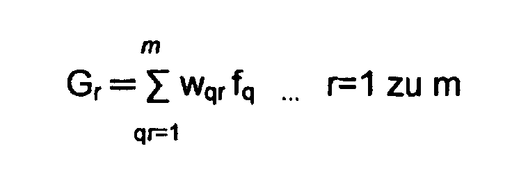
- Multiplication means multiply the set of populations f q by weights w qr defined for the same set of regions, and sum means then sum the products to produce a set of new values for G r , where
- the complete set ⁇ P 1 ....P m ⁇ of the P r collected is the welding signature.
- the weights w qr are chosen to produce a welding signature which contains as much information about the properties of the final weld as possible for a given sampling rate and size. This may be done experimentally, by trial and error adjustment or by knowledge of the physical process. Since there is some statistical noise in the sample, it is useful to choose the w qr to smooth the welding signature.
- the function F is chosen to maximise the sensitivity of the welding signature to changes in the quality of the final weld.
- the sampling means repetitively provides a series of values and a new welding signature is produced for each series.
- the reference signature can also be calculated continuously during welding from previous sampling.
- the reference is a weighted average of the x signatures S 1 , S 2 , S 3 ....S x where S 1 is the most recent signature calculated, S 2 is the signature calculated before that and so on.
- W 1 to W x are signature weighting factors.
- the choice of the signature weighting factors W 1 to W x determines whether the reference represents an average of weld signature behaviour over a relatively long period of time or represents recent welding behaviour.
- Weld quality result calculation means then compare the welding signatures with the reference welding signature to produce a measure of weld quality.
- U S - ( S . R ) R ( R . R ) where A.B is the inner product of two signatures A and B. If U is zero there is a perfect match.
- the quality factor q may be defined by
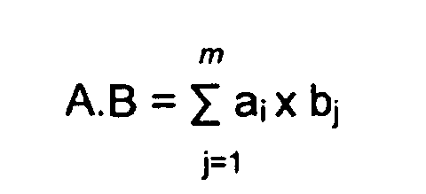
- the inner, or dot, product of any two signatures A and B is defined by: where a j and b j are the adjusted region populations P r of the signatures A and B respectively.
- the invention provides a method of measuring weld quality comprising the steps of:
- generating a series of values for the second signal which depends upon at least some values of the first signal either explicitly or through a recurrence relation.
- Pairing corresponding values of the first and second signals
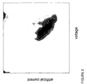
- This step could be visualised to involve plotting a two dimensional scatter plot, of the values of the first and second signals.
- the plot is then divided into regions.
- the regions need not be of equal size, and they may be smaller where population density is greatest and may be exponentially greater in dimension in both the voltage and current direction as they progress away from the point of greatest population density.
- the regions selected will usually be those around the area of greatest density of sample points. However, the regions selected need not be contiguous.
- the first artificial value A 1 may be set to zero.
- the artificial current values may then be plotted against the voltage values as shown in Figure 1 in order to visualise the process.
- the regions are chosen adaptively, based on the data itself. From a given set of reference data, a point (D 0 , A 0 ) is chosen to be at the mode of the sampled distribution; that is the point where the most data lies. The regions are chosen to have a width in the D direction which is smallest near the mode and tends to infinity at the edge regions. This means that resolution is improved where many data points are present.
- the width function is such that the width of the interval located at D w is proportional to: e ⁇ (D w - D o ) 2 /( ⁇ D) 2 where ⁇ D is the standard deviation of the D n , the set of values of the sampled voltage signal, and ⁇ is constant (set to unity in this example).
- (D q , A q ) and (D r , A r ) are the locations of the two regions q and r.
- weights are chosen, they are fixed during the monitoring process, the same for both the reference signature and the monitored signature.
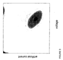
- the smoothed distribution, the set of region populations ⁇ G 1 ...G m ⁇ is shown in Figure 3.
- the single-valued monotonic function F is chosen to maximise the sensitivity of the welding signature to changes in the quality of the final weld.
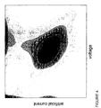
- the set of adjusted region populations ⁇ P 1 ...P m ⁇ , which is the final welding signature is shown in Figure 4. This can be compared with the signature from a reference weld.
- the weld quality measurement could be fed back in some way to control the welding operation if required.
- the invention may also be applied to situations using multiple references.
- R 1 and R 2 are the two reference signatures, recorded and stored during a welding run which produced a high-quality weldment. They should reflect the range of expected normal variation during the welding run. Examples are:
- a signature S has been collected during another run and is to be compared with R 1 and R 2 .
- R 1 and R 2 are independent signatures, that is, not the same signature or signatures whose elements, the adjusted region populations, differ from each other by a constant multiplying factor.
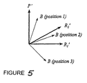
- P' and R 1 ' are orthogonal unit signatures in the two-dimensional linear signature subspace defined by R 1 and R 2 .
- Figure 5 illustrates the two dimensional subspace of the reference signatures with three possible locations for B. If B is inside the angle subtended by R 1 ' and R 2 ' (position 2), then the quality of the weld is satisfactory as far as the component B is concerned since the normalised welding signature is expected to move between R 1 ' and R 2 ' during normal welding as conditions change. However of B is in either of positions 1 or 3, this represents a discrepancy from ideal in addition to the discrepancy associated with non-zero C.
- R 1 ' or R 2 ' will be closest to S' and the quality q should be taken as the larger of R 1 '.S' and R 2 '.S'.
- the quality should be calculated successively for the three pairs of references R 1 and R 2 ; R 2 and R 3 ; and R 1 and R 3 , using the method already defined for a pair of references. The largest of the three resultant quality estimates is taken to be the final quality.
Landscapes
- Engineering & Computer Science (AREA)
- Mechanical Engineering (AREA)
- Physics & Mathematics (AREA)
- Plasma & Fusion (AREA)
- Theoretical Computer Science (AREA)
- Quality & Reliability (AREA)
- Spectroscopy & Molecular Physics (AREA)
- Investigating And Analyzing Materials By Characteristic Methods (AREA)
- Investigating Or Analyzing Materials By The Use Of Electric Means (AREA)
- Coating With Molten Metal (AREA)
- Analysing Materials By The Use Of Radiation (AREA)
- Arc Welding Control (AREA)
- Materials For Medical Uses (AREA)
- Pharmaceuticals Containing Other Organic And Inorganic Compounds (AREA)
- Sampling And Sample Adjustment (AREA)
Claims (30)
- Vorrichtung zur Qualitätsmessung der Schweißung, welche umfasst:Sensorsystem zum Abtasten entweder des Schweißstroms oder der Schweißspannung zur Bereitstellung einer Reihe von Messwerten für ein erstes Signal;ein sekundäres Sensorsystem zum Abtasten der Schweißspannung oder des Schweißstroms, welcher noch nicht zuvor vom Sensorsystem erfasst worden ist, um eine Reihe von Messwerten für ein zweites Signal bereitzustellen;Datenerfassungssystem zum Erfassen von Wertepaaren des ersten und zweiten Signals, die für die Qualitätsüberwachung in Signalgruppen anwendbar sind;Berechnungssystem zum Multiplizieren der Messwerte von zwei Gruppen-Populationsgrößen für jede Signalgruppe mittels eines Gewichtungsfaktors sowie zum Addieren der Ergebnisse für jede Signalgruppe;Speichersystem zum Abspeichern eines Referenzsatzes der Resultante-Abgleichs-Gruppenpopulationen, die für eine hochqualitative Schweißkonstruktion erfasst worden sind;Vergleichssystem zum Vergleichen des Referenzsatzes der Abgleichs-Gruppenpopulationen mit einem anderen Parametersatz, der mittels des Berechnungssystems erzeugt worden ist, für die Bereitstellung eines Messwertes der Schweißqualität für die Schweißung, von welcher der andere Parametersatz erzeugt worden ist.
- Vorrichtung zur Qualitätsmessung der Schweißung, welche umfasst:Sensorsystem zum Abtasten entweder des Schweißstroms oder der Schweißspannung zur Bereitstellung einer Reihe von Messwerten für ein erstes Signal;ein Signalgenerierungssystem unter Verwendung des ersten Signals zum Generieren einer Reihe von Messwerten für ein synthetisches, zweites Signal, das von zumindest einigen Messwerten des ersten Signals entweder direkt oder über eine zyklische Relation abhängt;Datenerfassungssystem zum Erfassen von Wertepaaren des ersten und zweiten Signals, die für die Qualitätsüberwachung in Signalgruppen anwendbar sind;Berechnungssystem zum Multiplizieren der Messwerte von zwei Gruppen-Populationsgrößen für jede Signalgruppe mittels eines Gewichtungsfaktors sowie zum Addieren der Ergebnisse für jede Signalgruppe;Speichersystem zum Abspeichern eines Referenzsatzes der Resultante-Abgleichs-Gruppenpopulationen, die für eine hochqualitative Schweißkonstruktion erfasst worden sind;Vergleichssystem zum Vergleichen des Referenzsatzes der Abgleichs-Gruppenpopulationen mit einem anderen Parametersatz, der mittels des Berechnungssystems erzeugt worden ist, zur Bereitstellung einer Maßeinheit der Schweißqualität für die Schweißung, von welcher der andere Parametersatz erzeugt worden ist.
- Vorrichtung nach Anspruch 2, wobei die Messwerte A n des synthetischen Signals vorgegeben werden von:
- Vorrichtung nach Anspruch 2, wobei die Messwerte A n des synthetischen Signals vorgegeben werden von:
- Vorrichtung nach Anspruch 2, wobei die Messwerte A n des synthetischen Signals vorgegeben werden von:
- Vorrichtung nach einem der vorangehenden Ansprüche, wobei die Gruppenpaare, welche durch das Datenerfassungssystem erfasst worden sind, jene sind, die innerhalb der ausgewählten Bereiche von zwei Größen-Histogrammen der Messwerte des ersten und zweiten Signals liegen.
- Vorrichtung nach Anspruch 6, wobei die Bereiche nicht von gleicher Größe sind.
- Vorrichtung nach Anspruch 7, wobei die Bereiche dort kleiner sind, wo die Dichte der Stichprobenpunkte größer ist.
- Vorrichtung nach einem der Ansprüche 6, 7 oder 8, wobei die ausgewählten Bereiche jene sind, welche die größte Dichte an den Stichprobenpunkten aufweisen.
- Vorrichtung nach Anspruch 1 oder 2, wobei das Berechnungssystem die Gruppenpopulationsdichten fη addiert, die durch die Gewichtungsfaktoren wqr für einen Satz von m -Bereichen zur Erzeugung eines Satzes von Gewichtungs-Gruppenpopulationen G1, G2 zu Gm gewichtet worden sind, welcher entspricht:

- Vorrichtung nach Anspruch 10, wobei das Berechnungssystem auch eine monotone, eindeutig bestimmte Funktion F auf jedem der Gr-Werte anwendet, um den Satz von Werten P1, P2 zu Pm zu erzeugen, welcher entspricht:
- Vorrichtung nach Anspruch 11, wobei das Vergleichssystem eine Schweißsignatur vergleicht, die von einem Referenzsatz der gewichteten Gruppenpopulationen mit einer Schweißsignatur erzeugt wurde, welche wiederum von einem anderen Parametersatz generiert worden ist.
- Vorrichtung nach Anspruch 12, wobei eine einzige Referenzsignatur S vorhanden ist, in der die Schweißsignatur S einer Schweißung und ein Qualitätsfaktor q der Schweißung wie folgt definiert werden:und aj und bj die Pr der Signaturen A bzw. B ergeben.

- Vorrichtung nach Anspruch 12, wobei zwei Referenzsignaturen R1 und R2 vorgegeben sind, in denen die Schweißsignatur S einer Schweißung und ein Qualitätsfaktor q der Schweißung wie folgt definiert werden:wobei das innere Produkt oder Skalarprodukt von jeder der zwei Signaturen A und B definiert werden durch:eine Standard- oder Einheitssignatur U' wird errechnet aus irgendeiner Signatur U als Ueine Signatur P - orthogonal zu R1 - wird vorgegeben durchund aj und bj die Pτ der Signaturen A bzw. B ergeben,

P ergibt ungleich Null, vorausgesetzt dass R1 und R2 unabhängige Signaturen sind, das heißt, dass sie nicht die gleiche Signatur bzw. Signaturen sind, deren Elemente - die Abgleichs-Bereichspopulationen - sich voneinander durch einen konstanten Multiplikationsfaktor unterscheiden;
P' und R1' sind orthogonale Einheitssignaturen in dem zweidimensionalen Linearsignatur-Unterschritt, der durch R1 und R2 definiert wird, und die Komponente B von S', die in dem Unterschritt liegt, ergibt: - Vorrichtung nach Anspruch 12, wobei drei Referenzsignaturen R1, R2 und R3 vorgegeben sind, wird eine Schweißsignatur S der Schweißung und ein Qualitätsfaktor q der Schweißung wie folgt definiert:wobei das innere Produkt oder Skalarprodukt von jeder der zwei Signaturen A und B definiert wird durch:eine Standard- oder Einheitssignatur U' wird errechnet aus irgendeiner Signatur U als Ueine Signatur P - orthogonal zu R1 - wird vorgegeben durchund aj und bj das Pτ der Signaturen A bzw. B ergeben,

wobei die Komponente von S' in dem dreidimensionalen Unterschritt, der durch R1, R2 und R3 erzeugt wird, ergibt: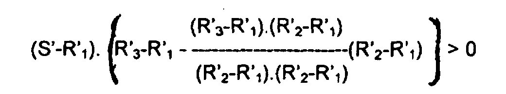
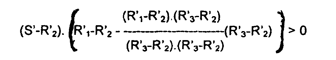 wenn sämtliche dieser Konditionen erfüllt werden, dann wird die Qualität q vorgegeben durch
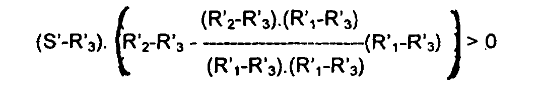
- Verfahren zur Qualitätsmessung, welches folgende Schritte umfasst:Abtasten entweder des Schweißstroms oder der Schweißspannung zur Bereitstellung einer Reihe von Messwerten für ein erstes Signal;Abtasten der Schweißspannung oder des Schweißstroms, die noch nicht zuvor abgetastet worden sind, um eine Reihe von Messwerten für ein zweites Signal bereitzustellen;Paarbildung von korrespondierenden Messwerten des ersten und zweiten Signals;Erfassen von Messwertpaaren, die für die Qualitätsüberwachung in Signalgruppen anwendbar sind;Errechnen der Ergebnisse von zwei Gruppen-Populationsgrößen mit feststehenden Gewichtungsfaktoren, die für die gleichen Gruppen definiert wurden, und Addieren der Ergebnisse für jede Gruppe, um einen neuen Parametersatz von gewichteten Gruppenpopulationen zu erzeugen;Abspeichern eines Referenzsatzes von Abgleichs-Gruppenpopulationen, die aus dem Produzieren einer hochqualitativen Schweißkonstruktion erhalten worden sind, oder alternativ dazu: Bestimmen eines Referenzsatzes aus einem Durchschnittswert von Sätzen der Abgleichs-Gruppenpopulationen, die zuvor errechnet worden sind; undVergleichen des Referenzsatzes der Abgleichs-Gruppenpopulationen mit einem weiteren Parametersatz, um eine Qualitätsmessung der Schweißung zu erzeugen, aus welcher der andere Parametersatz erzeugt wurde.
- Verfahren zur Qualitätsmessung, welches folgende Schritte umfasst:Abtasten entweder des Schweißstroms oder der Schweißspannung zur Bereitstellung einer Reihe von Messwerten für ein erstes Signal;Generieren einer Reihe von Messwerten für ein synthetisches, zweites Signal, das von zumindest einigen Messwerten des ersten Signals entweder direkt oder über eine zyklische Relation abhängt;Paarbildung von korrespondierenden Messwerten des ersten und zweiten Signals;Erfassen von Messwertpaaren, die für die Qualitäts-Monitorüberwachung in Gruppen anwendbar sind;Errechnen der Ergebnisse von zwei Gruppen-Populationsgrößen mit feststehenden Gewichtungsfaktoren, die für die gleichen Gruppen definiert wurden, und Addieren der Ergebnisse für jede Gruppe, um einen neuen Parametersatz von gewichteten Gruppenpopulationen zu erzeugen;Abspeichern eines Referenzsatzes von Abgleichs-Gruppenpopulationen, die aus dem Produzieren einer hochqualitativen Schweißkonstruktion erhalten worden sind, oder alternativ dazu: Bestimmen eines Referenzsatzes aus einem Durchschnittswert von Sätzen der Abgleichs-Gruppenpopulationen, die zuvor errechnet worden sind; undVergleichen des Referenzsatzes der Abgleichs-Gruppenpopulationen mit einem weiteren Satz, um eine Qualitätsmessung der Schweißung zu erzeugen, aus welcher der andere Parametersatz erzeugt wurde.
- Verfahren nach Anspruch 17, wobei die Messwerte A n des synthetischen Signals vorgegeben werden von:
- Verfahren nach Anspruch 17, wobei die Messwerte A n des synthetischen Signals vorgegeben werden von:
- Verfahren nach Anspruch 17, wobei die Messwerte A n des synthetischen Signals vorgegeben werden von:
- Verfahren nach einem der vorangehenden Ansprüche 16 bis 20, wobei die Gruppenpaare, welche durch das Datenerfassungssystem erfasst worden sind, jene sind, die innerhalb der ausgewählten Bereiche von zwei Größen-Histogrammen der Messwerte des ersten und zweiten Signals liegen.
- Verfahren nach Anspruch 21, wobei die Bereiche nicht von gleicher Größe sind.
- Verfahren nach Anspruch 22, wobei die Bereiche dort kleiner sind, wo die Dichte der Stichprobenpunkte größer ist.
- Verfahren nach einem der Ansprüche 21, 22 oder 23, wobei die ausgewählten Bereiche jene. sind, welche die größte Dichte an den Stichprobenpunkten aufweisen.
- Verfahren nach Anspruch 16 oder 17, wobei der Berechnungsschritt die Gruppenpopulationsdichten fq addiert, die durch Gewichtungsfaktoren wqr für einen Satz von m -Gruppen gewichtet sind, um einen Parametersatz von Gewichtungs-Gruppenpopulationen zu erzeugen, welcher entspricht:
- Verfahren nach Anspruch 25, wobei der Berechnungsschritt auch eine monotone, eindeutig bestimmte Funktion F auf jeder der gewichteten Gruppenpopulationen Gr anwendet, um einen neuen Parametersatz von Abgleichs-Gruppenpopulationen Pr zu erzeugen, welcher entspricht:
- Verfahren nach Anspruch 26, wobei der Vergleichsschritt eine Schweißsignatur vergleicht, die von einem Referenzsatz der Abgleichs-Gruppenpopulationen mit einer von einem anderen Parametersatz produzierten Schweißsignatur erzeugt worden ist.
- Verfahren nach Anspruch 27, wobei eine einzige Referenzsignatur R vorhanden ist, wird eine Schweißsignatur S von einer Schweißung und ein Qualitätsfaktor q der Schweißung wie folgt definiert:und wobei aj und bj die Abgleichs-Bereichspopulationen der Signaturen A bzw. B ergeben.

- Verfahren nach Anspruch 27, wobei zwei Referenzsignaturen R1 und R2 vorhanden sind, in denen eine Schweißsignatur S der Schweißung und ein Qualitätsfaktor q der Schweißung wie folgt definiert werden:wobei das innere Produkt oder Skalarprodukt von jeder der zwei Signaturen A und B definiert wird durch:eine Standard- oder Einheitssignatur U' wird aus irgendeiner Signatur U errechnet alseine Signatur P - orthogonal zu R1 - wird vorgegeben durchund aj und bj die Pr der Signaturen A bzw. B ergeben,

P ergibt ungleich Null, vorausgesetzt dass R1 und R2 unabhängige Signaturen sind, das heißt, dass sie nicht die gleiche Signatur bzw. Signaturen sind, deren Elemente - die Abgleichs-Bereichspopulationen - sich voneinander durch einen konstanten Multiplikationsfaktor unterscheiden;
P' und R1' sind orthogonale Einheitssignaturen in dem zweidimensionalen Linearsignatur-Unterschritt, der durch R1 und R2 definiert worden ist, und die Komponente B von S', die in dem Unterschritt liegt, ergibt: - Verfahren nach Anspruch 27, wobei drei Referenzsignaturen R1, R2 und R3 vorgegeben sind, wird die Schweißsignatur S der Schweißung und ein Qualitätsfaktor q der Schweißung wie folgt definiert:wobei das innere Produkt oder Skalarprodukt von jeder der zwei Signaturen A und B definiert wird durch:eine Standard- oder Einheitssignatur U' wird errechnet aus irgendeiner Signatur U alseine Signatur P - orthogonal zu R1 - wird vorgegeben durchund aj und bj die Pr der Signaturen A bzw. B ergeben,
wobei die Komponente von S' in dem dreidimensionalen Unterschritt, der durch R1, R2 und R3 erzeugt wurde, ergibt:
 wenn sämtliche dieser Konditionen erfüllt werden, dann wird die Qualität q vorgegeben durch
Applications Claiming Priority (3)
| Application Number | Priority Date | Filing Date | Title |
|---|---|---|---|
| AUPO6073A AUPO607397A0 (en) | 1997-04-08 | 1997-04-08 | Weld quality measurement |
| AUPO607397 | 1997-04-08 | ||
| PCT/AU1998/000244 WO1998045078A1 (en) | 1997-04-08 | 1998-04-08 | Weld quality measurement |
Publications (3)
| Publication Number | Publication Date |
|---|---|
| EP1007263A1 EP1007263A1 (de) | 2000-06-14 |
| EP1007263A4 EP1007263A4 (de) | 2001-11-21 |
| EP1007263B1 true EP1007263B1 (de) | 2003-09-17 |
Family
ID=3800372
Family Applications (1)
| Application Number | Title | Priority Date | Filing Date |
|---|---|---|---|
| EP98913436A Expired - Lifetime EP1007263B1 (de) | 1997-04-08 | 1998-04-08 | Qualitätsmessung der schweissung |
Country Status (11)
| Country | Link |
|---|---|
| US (1) | US6288364B1 (de) |
| EP (1) | EP1007263B1 (de) |
| KR (1) | KR100503778B1 (de) |
| AT (1) | ATE249906T1 (de) |
| AU (1) | AUPO607397A0 (de) |
| CA (1) | CA2285561C (de) |
| DE (1) | DE69818275T2 (de) |
| DK (1) | DK1007263T3 (de) |
| ES (1) | ES2202826T3 (de) |
| PT (1) | PT1007263E (de) |
| WO (1) | WO1998045078A1 (de) |
Families Citing this family (48)
| Publication number | Priority date | Publication date | Assignee | Title |
|---|---|---|---|---|
| AU763689B2 (en) * | 1999-12-15 | 2003-07-31 | University Of Sydney, The | Welding assessment |
| JP2003516863A (ja) * | 1999-12-15 | 2003-05-20 | ザ・ユニバーシティ・オブ・シドニー | 溶接評価 |
| US6441342B1 (en) * | 2000-11-20 | 2002-08-27 | Lincoln Global, Inc. | Monitor for electric arc welder |
| KR100428050B1 (ko) * | 2001-06-25 | 2004-04-28 | 한국과학기술원 | 아크용접의 품질평가 방법 |
| JP4667678B2 (ja) * | 2001-09-20 | 2011-04-13 | 中央精機株式会社 | アーク溶接品質評価装置 |
| DE10204495C1 (de) * | 2002-02-04 | 2003-07-03 | Tech Fachhochschule Wildau | Prüfeinrichtung für Schweißstromquellen |
| US6670574B1 (en) * | 2002-07-31 | 2003-12-30 | Unitek Miyachi Corporation | Laser weld monitor |
| DE102006038786A1 (de) | 2006-08-18 | 2008-02-21 | Robert Bosch Gmbh | Steuerung einer Schweißvorrichtung |
| US9104195B2 (en) | 2006-12-20 | 2015-08-11 | Lincoln Global, Inc. | Welding job sequencer |
| US9937577B2 (en) | 2006-12-20 | 2018-04-10 | Lincoln Global, Inc. | System for a welding sequencer |
| US10994358B2 (en) | 2006-12-20 | 2021-05-04 | Lincoln Global, Inc. | System and method for creating or modifying a welding sequence based on non-real world weld data |
| US9483959B2 (en) | 2008-08-21 | 2016-11-01 | Lincoln Global, Inc. | Welding simulator |
| US8911237B2 (en) | 2008-08-21 | 2014-12-16 | Lincoln Global, Inc. | Virtual reality pipe welding simulator and setup |
| US9318026B2 (en) | 2008-08-21 | 2016-04-19 | Lincoln Global, Inc. | Systems and methods providing an enhanced user experience in a real-time simulated virtual reality welding environment |
| US9196169B2 (en) | 2008-08-21 | 2015-11-24 | Lincoln Global, Inc. | Importing and analyzing external data using a virtual reality welding system |
| US9280913B2 (en) | 2009-07-10 | 2016-03-08 | Lincoln Global, Inc. | Systems and methods providing enhanced education and training in a virtual reality environment |
| US8834168B2 (en) | 2008-08-21 | 2014-09-16 | Lincoln Global, Inc. | System and method providing combined virtual reality arc welding and three-dimensional (3D) viewing |
| US8851896B2 (en) | 2008-08-21 | 2014-10-07 | Lincoln Global, Inc. | Virtual reality GTAW and pipe welding simulator and setup |
| US8884177B2 (en) | 2009-11-13 | 2014-11-11 | Lincoln Global, Inc. | Systems, methods, and apparatuses for monitoring weld quality |
| US9330575B2 (en) | 2008-08-21 | 2016-05-03 | Lincoln Global, Inc. | Tablet-based welding simulator |
| US8274013B2 (en) | 2009-03-09 | 2012-09-25 | Lincoln Global, Inc. | System for tracking and analyzing welding activity |
| US9773429B2 (en) | 2009-07-08 | 2017-09-26 | Lincoln Global, Inc. | System and method for manual welder training |
| US9221117B2 (en) | 2009-07-08 | 2015-12-29 | Lincoln Global, Inc. | System for characterizing manual welding operations |
| US10748447B2 (en) | 2013-05-24 | 2020-08-18 | Lincoln Global, Inc. | Systems and methods providing a computerized eyewear device to aid in welding |
| US9011154B2 (en) | 2009-07-10 | 2015-04-21 | Lincoln Global, Inc. | Virtual welding system |
| US8569655B2 (en) | 2009-10-13 | 2013-10-29 | Lincoln Global, Inc. | Welding helmet with integral user interface |
| US9468988B2 (en) | 2009-11-13 | 2016-10-18 | Lincoln Global, Inc. | Systems, methods, and apparatuses for monitoring weld quality |
| US8569646B2 (en) * | 2009-11-13 | 2013-10-29 | Lincoln Global, Inc. | Systems, methods, and apparatuses for monitoring weld quality |
| CA2821671C (en) | 2010-12-13 | 2018-01-09 | Edison Welding Institute, Inc. | Welding training system |
| US20160093233A1 (en) | 2012-07-06 | 2016-03-31 | Lincoln Global, Inc. | System for characterizing manual welding operations on pipe and other curved structures |
| US9767712B2 (en) | 2012-07-10 | 2017-09-19 | Lincoln Global, Inc. | Virtual reality pipe welding simulator and setup |
| US10930174B2 (en) | 2013-05-24 | 2021-02-23 | Lincoln Global, Inc. | Systems and methods providing a computerized eyewear device to aid in welding |
| US20150072323A1 (en) | 2013-09-11 | 2015-03-12 | Lincoln Global, Inc. | Learning management system for a real-time simulated virtual reality welding training environment |
| US10083627B2 (en) | 2013-11-05 | 2018-09-25 | Lincoln Global, Inc. | Virtual reality and real welding training system and method |
| US9836987B2 (en) | 2014-02-14 | 2017-12-05 | Lincoln Global, Inc. | Virtual reality pipe welding simulator and setup |
| CN106233358A (zh) | 2014-06-02 | 2016-12-14 | 林肯环球股份有限公司 | 用于人工焊工培训的系统和方法 |
| DE102015114957A1 (de) * | 2015-09-07 | 2017-03-09 | Harms + Wende Gmbh & Co. Kg | Elektrisches Schweißverfahren |
| CN105750754B (zh) * | 2016-05-06 | 2018-01-16 | 广州市精源电子设备有限公司 | 电阻点焊质量影响因素辨识方法与系统 |
| EP3319066A1 (de) | 2016-11-04 | 2018-05-09 | Lincoln Global, Inc. | Magnetische frequenzwahl für elektromagnetische positionsverfolgung |
| US20180130226A1 (en) | 2016-11-07 | 2018-05-10 | Lincoln Global, Inc. | System and method for calibrating a welding trainer |
| US10913125B2 (en) | 2016-11-07 | 2021-02-09 | Lincoln Global, Inc. | Welding system providing visual and audio cues to a welding helmet with a display |
| US10997872B2 (en) | 2017-06-01 | 2021-05-04 | Lincoln Global, Inc. | Spring-loaded tip assembly to support simulated shielded metal arc welding |
| US11475792B2 (en) | 2018-04-19 | 2022-10-18 | Lincoln Global, Inc. | Welding simulator with dual-user configuration |
| US11557223B2 (en) | 2018-04-19 | 2023-01-17 | Lincoln Global, Inc. | Modular and reconfigurable chassis for simulated welding training |
| GB2616336A (en) * | 2021-12-22 | 2023-09-06 | Cavendish Nuclear Ltd | Improvements in and relating to welding and quality control |
| CA3240143A1 (en) * | 2021-12-22 | 2023-06-29 | Randika Kosala Wathavana VITHANAGE | Improvements in and relating to welding and quality control |
| DE102022208184A1 (de) * | 2022-08-05 | 2024-02-08 | Kjellberg Stiftung, rechtsfähige Stiftung des bürgerlichen Rechts | Verfahren und Vorrichtung zum Erkennen eines Prozesszustands eines Plasmalichtbogenverfahrens |
| CN118671145B (zh) * | 2024-08-14 | 2024-10-22 | 天津商科数控技术股份有限公司 | 一种焊接质量检测方法、装置、设备和存储介质 |
Family Cites Families (11)
| Publication number | Priority date | Publication date | Assignee | Title |
|---|---|---|---|---|
| US4024371A (en) * | 1974-12-18 | 1977-05-17 | Kelsey-Hayes Company | Welding monitoring and control system |
| HU188832B (en) * | 1983-01-26 | 1986-05-28 | Retfalvi,Ferenc,Hu | Method and apparatus for securing the weld quality during operation, for marking the defect spots on piece and for certifying the quality |
| JPH0815669B2 (ja) * | 1988-07-06 | 1996-02-21 | 日本電装株式会社 | 抵抗溶接用制御装置 |
| DE3936329A1 (de) * | 1989-10-27 | 1991-05-08 | Innovationsgesellschaft Fuer F | Verfahren zur automatischen parameterbestimmung fuer prozessregelsysteme mit unbekanntem uebertragungsverhalten, insbesondere fuer prozessregelsysteme zum widerstandspunktschweissen, und vorrichtung zur durchfuehrung des verfahrens |
| US5270516A (en) | 1991-04-01 | 1993-12-14 | Matsushita Electric Industrial Co., Ltd. | Arc welding machine |
| FR2694899B1 (fr) | 1992-08-19 | 1994-09-23 | Paul Leon | Procédé de mesure d'une grandeur représentative d'une caractéristique physique et/ou mécanique d'une soudure par points, applications de ce procédé au soudage par points. |
| JP3322448B2 (ja) * | 1993-07-16 | 2002-09-09 | 小原株式会社 | 抵抗溶接制御方法 |
| DE4330914A1 (de) | 1993-09-11 | 1995-03-23 | Bosch Gmbh Robert | Verfahren zum Widerstandsschweißen |
| JPH07303966A (ja) * | 1994-05-11 | 1995-11-21 | Fanuc Ltd | ロボット制御装置 |
| US5521354A (en) * | 1994-06-21 | 1996-05-28 | Caterpillar Inc. | Method for arc welding fault detection |
| DE19539038A1 (de) | 1995-10-20 | 1997-04-24 | Ewm High Tech Precision Schwei | Lichtbogenschweißgerät mit einem wechselstromgespeisten Gleichrichter |
-
1997
- 1997-04-08 AU AUPO6073A patent/AUPO607397A0/en not_active Abandoned
-
1998
- 1998-04-08 DE DE69818275T patent/DE69818275T2/de not_active Expired - Fee Related
- 1998-04-08 KR KR10-1999-7009259A patent/KR100503778B1/ko not_active Expired - Fee Related
- 1998-04-08 CA CA002285561A patent/CA2285561C/en not_active Expired - Fee Related
- 1998-04-08 PT PT98913436T patent/PT1007263E/pt unknown
- 1998-04-08 US US09/402,717 patent/US6288364B1/en not_active Expired - Fee Related
- 1998-04-08 ES ES98913436T patent/ES2202826T3/es not_active Expired - Lifetime
- 1998-04-08 EP EP98913436A patent/EP1007263B1/de not_active Expired - Lifetime
- 1998-04-08 AT AT98913436T patent/ATE249906T1/de not_active IP Right Cessation
- 1998-04-08 DK DK98913436T patent/DK1007263T3/da active
- 1998-04-08 WO PCT/AU1998/000244 patent/WO1998045078A1/en not_active Ceased
Also Published As
| Publication number | Publication date |
|---|---|
| EP1007263A4 (de) | 2001-11-21 |
| ATE249906T1 (de) | 2003-10-15 |
| CA2285561C (en) | 2004-07-20 |
| DE69818275T2 (de) | 2004-04-08 |
| CA2285561A1 (en) | 1998-10-15 |
| DE69818275D1 (de) | 2003-10-23 |
| EP1007263A1 (de) | 2000-06-14 |
| WO1998045078A1 (en) | 1998-10-15 |
| US6288364B1 (en) | 2001-09-11 |
| DK1007263T3 (da) | 2004-02-02 |
| KR100503778B1 (ko) | 2005-07-26 |
| AUPO607397A0 (en) | 1997-05-01 |
| ES2202826T3 (es) | 2004-04-01 |
| KR20010006180A (ko) | 2001-01-26 |
| PT1007263E (pt) | 2004-02-27 |
Similar Documents
| Publication | Publication Date | Title |
|---|---|---|
| EP1007263B1 (de) | Qualitätsmessung der schweissung | |
| US20030094478A1 (en) | Welding assessment | |
| Zhang et al. | Prediction of surface roughness in end face milling based on Gaussian process regression and cause analysis considering tool vibration | |
| US20130248505A1 (en) | Welding quality classification apparatus | |
| CN100451895C (zh) | 用于控制工业过程的质量的方法 | |
| US6064029A (en) | Apparatus for controlling the quality of a resistance spot weld and method therefor | |
| CN113916983B (zh) | 用于检测铺粉式金属3d打印设备刮刀损伤的装置 | |
| US7020046B1 (en) | System and method for target motion analysis with intelligent parameter evaluation plot | |
| CN110596541A (zh) | 一种基于指纹图的局部放电定位方法与系统 | |
| AU741965B2 (en) | Weld quality measurement | |
| EP2003470B1 (de) | Adaptive Radarkontrolle bei konstantem Fehlalarm | |
| KR102793030B1 (ko) | 에너지 시계열 데이터 기반 설비 이상상황 진단 장치 및 그 방법 | |
| CN116644305B (zh) | 基于多传感器数据决策融合的超声焊接质量预测方法 | |
| CN100464270C (zh) | 控制工业生产过程质量的方法及其系统 | |
| AU763689B2 (en) | Welding assessment | |
| Huang et al. | Multifractal analysis for gas metal arc welding | |
| CN120948923A (zh) | 一种避雷器参数测量系统及方法 | |
| US20250285024A1 (en) | Method for Generating a Training Dataset | |
| US20250355053A1 (en) | Measurement apparatus, electricity storage system, and measurement method | |
| US20250284968A1 (en) | Method for Generating a Training Dataset | |
| US20250283998A1 (en) | Measuring Device | |
| US20250283999A1 (en) | Method for Operating a Measuring Device | |
| EA050181B1 (ru) | Способ изготовления изделия путем трехмерной печати электродуговой наплавкой с интеллектуальной диагностикой динамической устойчивости процесса | |
| CN120606197A (zh) | 焊接方案的制定方法、相关装置及计算机存储介质 | |
| Hickmann et al. | Training and Interpretability of Deep-Neural Methods for Damage Calibration in Copper. |
Legal Events
| Date | Code | Title | Description |
|---|---|---|---|
| PUAI | Public reference made under article 153(3) epc to a published international application that has entered the european phase |
Free format text: ORIGINAL CODE: 0009012 |
|
| 17P | Request for examination filed |
Effective date: 19991025 |
|
| AK | Designated contracting states |
Kind code of ref document: A1 Designated state(s): AT BE CH CY DE DK ES FI FR GB GR IE IT LI LU MC NL PT SE |
|
| AX | Request for extension of the european patent |
Free format text: AL PAYMENT 19991025;LT PAYMENT 19991025;LV PAYMENT 19991025;MK PAYMENT 19991025;RO PAYMENT 19991025;SI PAYMENT 19991025 |
|
| A4 | Supplementary search report drawn up and despatched |
Effective date: 20011009 |
|
| AK | Designated contracting states |
Kind code of ref document: A4 Designated state(s): AT BE CH CY DE DK ES FI FR GB GR IE IT LI LU MC NL PT SE |
|
| RIC1 | Information provided on ipc code assigned before grant |
Free format text: 7B 23K 9/095 A, 7B 23K 11/25 B, 7B 23K 31/12 B |
|
| GRAH | Despatch of communication of intention to grant a patent |
Free format text: ORIGINAL CODE: EPIDOS IGRA |
|
| GRAS | Grant fee paid |
Free format text: ORIGINAL CODE: EPIDOSNIGR3 |
|
| GRAA | (expected) grant |
Free format text: ORIGINAL CODE: 0009210 |
|
| AK | Designated contracting states |
Kind code of ref document: B1 Designated state(s): AT BE CH CY DE DK ES FI FR GB GR IE IT LI LU MC NL PT SE |
|
| AX | Request for extension of the european patent |
Extension state: AL LT LV MK RO SI |
|
| PG25 | Lapsed in a contracting state [announced via postgrant information from national office to epo] |
Ref country code: CY Free format text: LAPSE BECAUSE OF FAILURE TO SUBMIT A TRANSLATION OF THE DESCRIPTION OR TO PAY THE FEE WITHIN THE PRESCRIBED TIME-LIMIT Effective date: 20030917 |
|
| REG | Reference to a national code |
Ref country code: GB Ref legal event code: FG4D |
|
| REG | Reference to a national code |
Ref country code: SE Ref legal event code: TRGR Ref country code: CH Ref legal event code: EP |
|
| REF | Corresponds to: |
Ref document number: 69818275 Country of ref document: DE Date of ref document: 20031023 Kind code of ref document: P |
|
| REG | Reference to a national code |
Ref country code: IE Ref legal event code: FG4D |
|
| PG25 | Lapsed in a contracting state [announced via postgrant information from national office to epo] |
Ref country code: GR Free format text: LAPSE BECAUSE OF FAILURE TO SUBMIT A TRANSLATION OF THE DESCRIPTION OR TO PAY THE FEE WITHIN THE PRESCRIBED TIME-LIMIT Effective date: 20031217 |
|
| REG | Reference to a national code |
Ref country code: CH Ref legal event code: NV Representative=s name: ISLER & PEDRAZZINI AG |
|
| REG | Reference to a national code |
Ref country code: DK Ref legal event code: T3 |
|
| LTIE | Lt: invalidation of european patent or patent extension |
Effective date: 20030917 |
|
| REG | Reference to a national code |
Ref country code: ES Ref legal event code: FG2A Ref document number: 2202826 Country of ref document: ES Kind code of ref document: T3 |
|
| PG25 | Lapsed in a contracting state [announced via postgrant information from national office to epo] |
Ref country code: LU Free format text: LAPSE BECAUSE OF NON-PAYMENT OF DUE FEES Effective date: 20040408 |
|
| PG25 | Lapsed in a contracting state [announced via postgrant information from national office to epo] |
Ref country code: MC Free format text: LAPSE BECAUSE OF NON-PAYMENT OF DUE FEES Effective date: 20040430 |
|
| ET | Fr: translation filed | ||
| PLBE | No opposition filed within time limit |
Free format text: ORIGINAL CODE: 0009261 |
|
| STAA | Information on the status of an ep patent application or granted ep patent |
Free format text: STATUS: NO OPPOSITION FILED WITHIN TIME LIMIT |
|
| 26N | No opposition filed |
Effective date: 20040618 |
|
| PGFP | Annual fee paid to national office [announced via postgrant information from national office to epo] |
Ref country code: NL Payment date: 20050403 Year of fee payment: 8 |
|
| PGFP | Annual fee paid to national office [announced via postgrant information from national office to epo] |
Ref country code: SE Payment date: 20050406 Year of fee payment: 8 Ref country code: PT Payment date: 20050406 Year of fee payment: 8 |
|
| PGFP | Annual fee paid to national office [announced via postgrant information from national office to epo] |
Ref country code: AT Payment date: 20050413 Year of fee payment: 8 |
|
| PGFP | Annual fee paid to national office [announced via postgrant information from national office to epo] |
Ref country code: FI Payment date: 20050414 Year of fee payment: 8 Ref country code: IE Payment date: 20050414 Year of fee payment: 8 |
|
| PGFP | Annual fee paid to national office [announced via postgrant information from national office to epo] |
Ref country code: DK Payment date: 20050415 Year of fee payment: 8 Ref country code: CH Payment date: 20050415 Year of fee payment: 8 |
|
| PGFP | Annual fee paid to national office [announced via postgrant information from national office to epo] |
Ref country code: ES Payment date: 20050527 Year of fee payment: 8 |
|
| PGFP | Annual fee paid to national office [announced via postgrant information from national office to epo] |
Ref country code: BE Payment date: 20050615 Year of fee payment: 8 |
|
| PG25 | Lapsed in a contracting state [announced via postgrant information from national office to epo] |
Ref country code: FI Free format text: LAPSE BECAUSE OF NON-PAYMENT OF DUE FEES Effective date: 20060408 Ref country code: AT Free format text: LAPSE BECAUSE OF NON-PAYMENT OF DUE FEES Effective date: 20060408 |
|
| PG25 | Lapsed in a contracting state [announced via postgrant information from national office to epo] |
Ref country code: SE Free format text: LAPSE BECAUSE OF NON-PAYMENT OF DUE FEES Effective date: 20060409 |
|
| PG25 | Lapsed in a contracting state [announced via postgrant information from national office to epo] |
Ref country code: IE Free format text: LAPSE BECAUSE OF NON-PAYMENT OF DUE FEES Effective date: 20060410 Ref country code: ES Free format text: LAPSE BECAUSE OF NON-PAYMENT OF DUE FEES Effective date: 20060410 |
|
| PG25 | Lapsed in a contracting state [announced via postgrant information from national office to epo] |
Ref country code: LI Free format text: LAPSE BECAUSE OF NON-PAYMENT OF DUE FEES Effective date: 20060430 Ref country code: CH Free format text: LAPSE BECAUSE OF NON-PAYMENT OF DUE FEES Effective date: 20060430 Ref country code: BE Free format text: LAPSE BECAUSE OF NON-PAYMENT OF DUE FEES Effective date: 20060430 |
|
| PGFP | Annual fee paid to national office [announced via postgrant information from national office to epo] |
Ref country code: IT Payment date: 20060430 Year of fee payment: 9 |
|
| PG25 | Lapsed in a contracting state [announced via postgrant information from national office to epo] |
Ref country code: DK Free format text: LAPSE BECAUSE OF NON-PAYMENT OF DUE FEES Effective date: 20060501 |
|
| PG25 | Lapsed in a contracting state [announced via postgrant information from national office to epo] |
Ref country code: PT Free format text: LAPSE BECAUSE OF NON-PAYMENT OF DUE FEES Effective date: 20061009 |
|
| PG25 | Lapsed in a contracting state [announced via postgrant information from national office to epo] |
Ref country code: NL Free format text: LAPSE BECAUSE OF NON-PAYMENT OF DUE FEES Effective date: 20061101 |
|
| REG | Reference to a national code |
Ref country code: PT Ref legal event code: MM4A Free format text: LAPSE DUE TO NON-PAYMENT OF FEES Effective date: 20061009 |
|
| REG | Reference to a national code |
Ref country code: DK Ref legal event code: EBP |
|
| REG | Reference to a national code |
Ref country code: CH Ref legal event code: PL |
|
| EUG | Se: european patent has lapsed | ||
| NLV4 | Nl: lapsed or anulled due to non-payment of the annual fee |
Effective date: 20061101 |
|
| REG | Reference to a national code |
Ref country code: IE Ref legal event code: MM4A |
|
| REG | Reference to a national code |
Ref country code: ES Ref legal event code: FD2A Effective date: 20060410 |
|
| BERE | Be: lapsed |
Owner name: THE *UNIVERSITY OF SYDNEY Effective date: 20060430 |
|
| PGFP | Annual fee paid to national office [announced via postgrant information from national office to epo] |
Ref country code: DE Payment date: 20080417 Year of fee payment: 11 |
|
| PGFP | Annual fee paid to national office [announced via postgrant information from national office to epo] |
Ref country code: FR Payment date: 20080414 Year of fee payment: 11 |
|
| PGFP | Annual fee paid to national office [announced via postgrant information from national office to epo] |
Ref country code: GB Payment date: 20080409 Year of fee payment: 11 |
|
| PG25 | Lapsed in a contracting state [announced via postgrant information from national office to epo] |
Ref country code: IT Free format text: LAPSE BECAUSE OF NON-PAYMENT OF DUE FEES Effective date: 20070408 |
|
| GBPC | Gb: european patent ceased through non-payment of renewal fee |
Effective date: 20090408 |
|
| REG | Reference to a national code |
Ref country code: FR Ref legal event code: ST Effective date: 20091231 |
|
| PG25 | Lapsed in a contracting state [announced via postgrant information from national office to epo] |
Ref country code: DE Free format text: LAPSE BECAUSE OF NON-PAYMENT OF DUE FEES Effective date: 20091103 |
|
| PG25 | Lapsed in a contracting state [announced via postgrant information from national office to epo] |
Ref country code: GB Free format text: LAPSE BECAUSE OF NON-PAYMENT OF DUE FEES Effective date: 20090408 Ref country code: FR Free format text: LAPSE BECAUSE OF NON-PAYMENT OF DUE FEES Effective date: 20091222 |