EP1007263B1 - Weld quality measurement - Google Patents
Weld quality measurement Download PDFInfo
- Publication number
- EP1007263B1 EP1007263B1 EP98913436A EP98913436A EP1007263B1 EP 1007263 B1 EP1007263 B1 EP 1007263B1 EP 98913436 A EP98913436 A EP 98913436A EP 98913436 A EP98913436 A EP 98913436A EP 1007263 B1 EP1007263 B1 EP 1007263B1
- Authority
- EP
- European Patent Office
- Prior art keywords
- signature
- values
- quality
- weld
- welding
- Prior art date
- Legal status (The legal status is an assumption and is not a legal conclusion. Google has not performed a legal analysis and makes no representation as to the accuracy of the status listed.)
- Expired - Lifetime
Links
Images

Classifications
-
- B—PERFORMING OPERATIONS; TRANSPORTING
- B23—MACHINE TOOLS; METAL-WORKING NOT OTHERWISE PROVIDED FOR
- B23K—SOLDERING OR UNSOLDERING; WELDING; CLADDING OR PLATING BY SOLDERING OR WELDING; CUTTING BY APPLYING HEAT LOCALLY, e.g. FLAME CUTTING; WORKING BY LASER BEAM
- B23K9/00—Arc welding or cutting
- B23K9/095—Monitoring or automatic control of welding parameters
-
- B—PERFORMING OPERATIONS; TRANSPORTING
- B23—MACHINE TOOLS; METAL-WORKING NOT OTHERWISE PROVIDED FOR
- B23K—SOLDERING OR UNSOLDERING; WELDING; CLADDING OR PLATING BY SOLDERING OR WELDING; CUTTING BY APPLYING HEAT LOCALLY, e.g. FLAME CUTTING; WORKING BY LASER BEAM
- B23K11/00—Resistance welding; Severing by resistance heating
- B23K11/24—Electric supply or control circuits therefor
- B23K11/25—Monitoring devices
- B23K11/252—Monitoring devices using digital means
-
- B—PERFORMING OPERATIONS; TRANSPORTING
- B23—MACHINE TOOLS; METAL-WORKING NOT OTHERWISE PROVIDED FOR
- B23K—SOLDERING OR UNSOLDERING; WELDING; CLADDING OR PLATING BY SOLDERING OR WELDING; CUTTING BY APPLYING HEAT LOCALLY, e.g. FLAME CUTTING; WORKING BY LASER BEAM
- B23K31/00—Processes relevant to this subclass, specially adapted for particular articles or purposes, but not covered by any single one of main groups B23K1/00 - B23K28/00
- B23K31/12—Processes relevant to this subclass, specially adapted for particular articles or purposes, but not covered by any single one of main groups B23K1/00 - B23K28/00 relating to investigating the properties, e.g. the weldability, of materials
- B23K31/125—Weld quality monitoring
-
- B—PERFORMING OPERATIONS; TRANSPORTING
- B23—MACHINE TOOLS; METAL-WORKING NOT OTHERWISE PROVIDED FOR
- B23K—SOLDERING OR UNSOLDERING; WELDING; CLADDING OR PLATING BY SOLDERING OR WELDING; CUTTING BY APPLYING HEAT LOCALLY, e.g. FLAME CUTTING; WORKING BY LASER BEAM
- B23K9/00—Arc welding or cutting
- B23K9/09—Arrangements or circuits for arc welding with pulsed current or voltage
- B23K9/091—Arrangements or circuits for arc welding with pulsed current or voltage characterised by the circuits
-
- B—PERFORMING OPERATIONS; TRANSPORTING
- B23—MACHINE TOOLS; METAL-WORKING NOT OTHERWISE PROVIDED FOR
- B23K—SOLDERING OR UNSOLDERING; WELDING; CLADDING OR PLATING BY SOLDERING OR WELDING; CUTTING BY APPLYING HEAT LOCALLY, e.g. FLAME CUTTING; WORKING BY LASER BEAM
- B23K9/00—Arc welding or cutting
- B23K9/095—Monitoring or automatic control of welding parameters
- B23K9/0953—Monitoring or automatic control of welding parameters using computing means
-
- H—ELECTRICITY
- H05—ELECTRIC TECHNIQUES NOT OTHERWISE PROVIDED FOR
- H05H—PLASMA TECHNIQUE; PRODUCTION OF ACCELERATED ELECTRICALLY-CHARGED PARTICLES OR OF NEUTRONS; PRODUCTION OR ACCELERATION OF NEUTRAL MOLECULAR OR ATOMIC BEAMS
- H05H1/00—Generating plasma; Handling plasma
- H05H1/24—Generating plasma
- H05H1/26—Plasma torches
- H05H1/32—Plasma torches using an arc
- H05H1/34—Details, e.g. electrodes, nozzles
- H05H1/3494—Means for controlling discharge parameters
Definitions
- This invention concerns weld quality measurement.
- it concerns an apparatus and a process for measuring on-line, while the welding process is under way, the quality of the resulting weldment.
- the invention is applicable to gas-metal arc welding, tungsten-inert gas welding, pulsed welding, resistance welding, submerged arc welding and to other welding processes where there is an arc plasma.
- the invention is an apparatus for measuring the quality of a weld.
- the apparatus comprises:
- a second sampling means may be employed to measure the other variable to provide a series of values for a second signal.
- a signal generating means uses the first signal to generate a series of values for an artificial second signal, which depends upon at least some values of the first signal either explicitly or through a recurrence relation.
- Pairing means identify corresponding values of the first and second signals.
- Collection means collect pairs of values which are useful for quality monitoring into groups or regions.
- the pairs collected could be visualised to be those that would fall within selected regions of a two dimensional scatter plot of the values of the first and second signals.
- the regions could be drawn on to such a visualisation.
- the regions need not be of equal size, and they may be smaller where population density is greatest and may be exponentially greater in dimension, in both the voltage and current direction, as they progress away from the point of greatest population density. Once the regions are chosen they are fixed during the monitoring process.
- the regions selected will usually be those around the area of greatest density of sample points. However, the regions selected need not be contiguous.
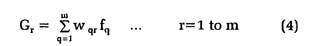
- Multiplication means multiply the set of populations f q by weights w qr defined for the same set of regions, and sum means then sum the products to produce a set of new values for G r , where
- the complete set ⁇ P 1 ....P m ⁇ of the P r collected is the welding signature.
- the weights w qr are chosen to produce a welding signature which contains as much information about the properties of the final weld as possible for a given sampling rate and size. This may be done experimentally, by trial and error adjustment or by knowledge of the physical process. Since there is some statistical noise in the sample, it is useful to choose the w qr to smooth the welding signature.
- the function F is chosen to maximise the sensitivity of the welding signature to changes in the quality of the final weld.
- the sampling means repetitively provides a series of values and a new welding signature is produced for each series.
- the reference signature can also be calculated continuously during welding from previous sampling.
- the reference is a weighted average of the x signatures S 1 , S 2 , S 3 ....S x where S 1 is the most recent signature calculated, S 2 is the signature calculated before that and so on.
- W 1 to W x are signature weighting factors.
- the choice of the signature weighting factors W 1 to W x determines whether the reference represents an average of weld signature behaviour over a relatively long period of time or represents recent welding behaviour.
- Weld quality result calculation means then compare the welding signatures with the reference welding signature to produce a measure of weld quality.
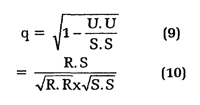
- U S - ( S . R ) R ( R . R ) where A.B is the inner product of two signatures A and B. If U is zero there is a perfect match.
- the quality factor q may be defined by
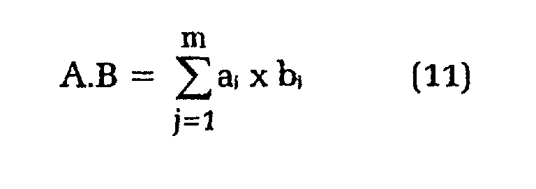
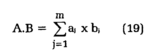
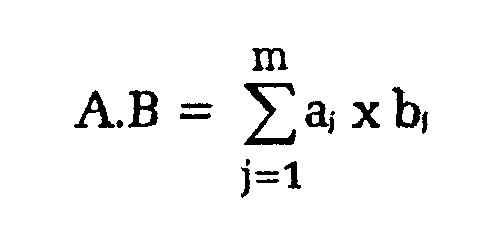
- the inner, or dot, product of any two signatures A and B is defined by: where a j and b j are the adjusted region populations P r of the signatures A and B respectively.
- the invention provides a method of measuring weld quality comprising the steps of:
- generating a series of values for the second signal which depends upon at least some values of the first signal either explicitly or through a recurrence relation.
- Pairing corresponding values of the first and second signals
- This step could be visualised to involve plotting a two dimensional scatter plot, of the values of the first and second signals.
- the plot is then divided into regions.
- the regions need not be of equal size, and they may be smaller where population density is greatest and may be exponentially greater in dimension in both the voltage and current direction as they progress away from the point of greatest population density.
- the regions selected will usually be those around the area of greatest density of sample points. However, the regions selected need not be contiguous.
- the first artificial value A 1 may be set to zero.
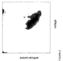
- the artificial current values may then be plotted against the voltage values as shown in Figure 1 in order to visualise the process.
- the regions are chosen adaptively, based on the data itself. From a given set of reference data, a point (D 0 , A 0 ) is chosen to be at the mode of the sampled distribution; that is the point where the most data lies. The regions are chosen to have a width in the D direction which is smallest near the mode and tends to infinity at the edge regions. This means that resolution is improved where many data points are present.
- the width function is such that the width of the interval located at D w is proportional to: e ⁇ (D w - D o ) 2 /( ⁇ D) 2 where ⁇ D is the standard deviation of the D n , the set of values of the sampled voltage signal, and ⁇ is constant (set to unity in this example).
- (D q , A q ) and (D r , A r ) are the locations of the two regions q and r.
- weights are chosen, they are fixed during the monitoring process, the same for both the reference signature and the monitored signature.
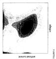
- the smoothed distribution, the set of region populations ⁇ G 1 ...G m ⁇ is shown in Figure 3.
- the single-valued monotonic function F is chosen to maximise the sensitivity of the welding signature to changes in the quality of the final weld.
- the set of adjusted region populations ⁇ P 1 ...P m ⁇ , which is the final welding signature is shown in Figure 4. This can be compared with the signature from a reference weld.
- the weld quality measurement could be fed back in some way to control the welding operation if required.
- the invention may also be applied to situations using multiple references.
- R 1 and R 2 are the two reference signatures, recorded and stored during a welding run which produced a high-quality weldment. They should reflect the range of expected normal variation during the welding run. Examples are:
- a signature S has been collected during another run and is to be compared with R 1 and R 2 .
- R 1 and R 2 are independent signatures, that is, not the same signature or signatures whose elements, the adjusted region populations, differ from each other by a constant multiplying factor.
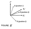
- P' and R 1 ' are orthogonal unit signatures in the two-dimensional linear signature subspace defined by R 1 and R 2 .
- Figure 5 illustrates the two dimensional subspace of the reference signatures with three possible locations for B. If B is inside the angle subtended by R 1 ' and R 2 ' (position 2), then the quality of the weld is satisfactory as far as the component B is concerned since the normalised welding signature is expected to move between R 1 ' and R 2 ' during normal welding as conditions change. However of B is in either of positions 1 or 3, this represents a discrepancy from ideal in addition to the discrepancy associated with non-zero C.
- R 1 ' or R 2 ' will be closest to S' and the quality q should be taken as the larger of R 1 '.S' and R 2 '.S'.
- the quality should be calculated successively for the three pairs of references R 1 and R 2 ; R 2 and R 3 ; and R 1 and R 3 , using the method already defined for a pair of references. The largest of the three resultant quality estimates is taken to be the final quality.
Landscapes
- Engineering & Computer Science (AREA)
- Mechanical Engineering (AREA)
- Physics & Mathematics (AREA)
- Plasma & Fusion (AREA)
- Quality & Reliability (AREA)
- Theoretical Computer Science (AREA)
- Spectroscopy & Molecular Physics (AREA)
- Investigating And Analyzing Materials By Characteristic Methods (AREA)
- Analysing Materials By The Use Of Radiation (AREA)
- Coating With Molten Metal (AREA)
- Investigating Or Analyzing Materials By The Use Of Electric Means (AREA)
- Sampling And Sample Adjustment (AREA)
- Arc Welding Control (AREA)
- Pharmaceuticals Containing Other Organic And Inorganic Compounds (AREA)
- Materials For Medical Uses (AREA)
Abstract
Description
- This invention concerns weld quality measurement. In particular it concerns an apparatus and a process for measuring on-line, while the welding process is under way, the quality of the resulting weldment. The invention is applicable to gas-metal arc welding, tungsten-inert gas welding, pulsed welding, resistance welding, submerged arc welding and to other welding processes where there is an arc plasma.
- The study of welding and cutting arc phenomena, involves the observation of both voltage and current signals having periods of milliseconds to seconds, or even micro-seconds. One way of monitoring these signals involves the use of high speed photography, and another is the use of oscillograms. The limitations inherent in the observation techniques and the difficulties in analysing the resulting data, make it difficult to provide a weld quality measurement in real time. Another way is to monitor the weld resistance, see FR-A-2 694 899.
- In a first aspect, the invention is an apparatus for measuring the quality of a weld. The apparatus comprises:
- sampling means to sample either the welding current or the welding voltage to provide a series of values for a first signal.
-
- A second sampling means may be employed to measure the other variable to provide a series of values for a second signal. Alternatively, a signal generating means uses the first signal to generate a series of values for an artificial second signal, which depends upon at least some values of the first signal either explicitly or through a recurrence relation. For example, where voltage V is measured, an artificial current I' can be mathematically generated using:
- This approximation can model the usual inductive-resistive circuit of a power supply but need not be an accurate model since the artificial signal need only provide information about the time history of the sequence.
- Using the symbols Dn for the real data sequence and An for the artificial sequence, two useful possibilities are
- Pairing means identify corresponding values of the first and second signals.
- Collection means collect pairs of values which are useful for quality monitoring into groups or regions. The pairs collected could be visualised to be those that would fall within selected regions of a two dimensional scatter plot of the values of the first and second signals. The regions could be drawn on to such a visualisation.
- The regions need not be of equal size, and they may be smaller where population density is greatest and may be exponentially greater in dimension, in both the voltage and current direction, as they progress away from the point of greatest population density. Once the regions are chosen they are fixed during the monitoring process.
- In the case of 'dip' or short circuiting metal transfer in gas metal arc welding, there are large oscillations in voltage and current.
- The regions selected will usually be those around the area of greatest density of sample points. However, the regions selected need not be contiguous.
- The population of sample points for each selected region can be represented by a two dimensional population density function fr for a set of regions r= 1 to m.
- Multiplication means multiply the set of populations fq by weights wqr defined for the same set of regions, and sum means then sum the products to produce a set of new values for Gr, where
- To produce the final adjusted region populations Pr a function F is applied to each of the Gr values:
- The complete set {P1....Pm} of the Pr collected is the welding signature.
- The weights wqr are chosen to produce a welding signature which contains as much information about the properties of the final weld as possible for a given sampling rate and size. This may be done experimentally, by trial and error adjustment or by knowledge of the physical process. Since there is some statistical noise in the sample, it is useful to choose the wqr to smooth the welding signature. The function F is chosen to maximise the sensitivity of the welding signature to changes in the quality of the final weld.
- The sampling means repetitively provides a series of values and a new welding signature is produced for each series. Memory means retain a welding signature R={P1...Pm} collected under welding conditions known to be satisfactory and producing a high quality weldment. This may be reference data saved for some time, or could be data collected at the start of a welding run. In the case of a robotic welding, where a sequence of welds is carried out under conditions which may vary, a sequence of reference signatures may be stored and recalled when needed.
- The reference signature can also be calculated continuously during welding from previous sampling. In this case the reference is a weighted average of the x signatures S1, S2, S3 ....Sx where S1 is the most recent signature calculated, S2 is the signature calculated before that and so on. The reference signature R is determined from the weighted average
- When signatures are multiplied or divided by a number, it is understood that every adjusted region population in the signature should be multiplied or divided by the number to produce a new signature. Similarly when signatures are added or subtracted, the matching adjusted region populations of each signature are added or subtracted, that is, the adjusted region population numbered j in one signature is added or subtracted from the adjusted region population numbered j in the other signature for j=1, 2 up to m. The equation above can then be written more succinctly as
- Weld quality result calculation means then compare the welding signatures with the reference welding signature to produce a measure of weld quality.
- The part U of a welding signature S which is does not match the reference signature R is given by
- The quality factor q may be defined by
- The quality q will be unity if U is zero and zero if U=S and S.R=0. A value of q=1 would indicate perfect quality. As welding conditions deviate from ideal due to any faults in the welding process, S will no longer match R and q<1.
- The inner, or dot, product of any two signatures A and B is defined by:where aj and bj are the adjusted region populations Pr of the signatures A and B respectively.
- In another aspect, as currently envisaged, the invention provides a method of measuring weld quality comprising the steps of:
- Sampling either the welding current or the welding voltage to provide a series of values for a first signal.
- Sampling the other variable to provide a series of values for a second signal.
-
- Alternatively, generating a series of values for the second signal, which depends upon at least some values of the first signal either explicitly or through a recurrence relation.
- Pairing corresponding values of the first and second signals.
- Collecting pairs of values which are useful for quality monitoring. This step could be visualised to involve plotting a two dimensional scatter plot, of the values of the first and second signals. The plot is then divided into regions. The regions need not be of equal size, and they may be smaller where population density is greatest and may be exponentially greater in dimension in both the voltage and current direction as they progress away from the point of greatest population density. Once the regions are chosen they are fixed during the monitoring process. The regions selected will usually be those around the area of greatest density of sample points. However, the regions selected need not be contiguous.
- The process then continues by representing the population of sample points for each selected region by a two dimensional population density function fr for a set of regions r=1 to m.
- Multiplying the set of populations fq by weights wqr defined for the same set of regions.
- Summing the products to produce a set of new values for Gr, where

- Applying a function F to each of the Gr to produce the adjusted region populations Pr:
- Identifying the complete set {P1....Pm} of the Pr collected as the welding signature.
- Repetitively sampling series of values to provide successive welding signatures.
- Storing a welding signature R={P1...Pm} collected under welding conditions known to be satisfactory and producing a high quality weldment, or, alternatively, calculating a weighted average reference from previous signatures.
- Comparing the welding signatures with the reference welding signature to produce a measure of weld quality
- An example of the invention will now be described with reference the accompanying drawings, in which:
- Figure 1 is a two dimensional scatter plot of measured voltage and synthetic current;
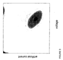
- Figure 2 is a population density distribution of selected regions of Figure 1;
- Figure 3 is a weighted version of the population density of Figure 2;
- Figure 4 is an adjusted version of the population density of Figure 3 and shows a welding signature; and
- Figure 5 is a graphical representation of a two dimensional subspace of reference signatures.
-
- In short-circuiting transfer in gas-metal arc welding, short circuiting occurs repetitively. The voltage wave form will as a result show generally rectangular pulses at about 20 volts separated by regions where the voltage falls to near zero. This voltage is sampled (s) 1024 times with a sampling time interval (Δt) of 0.5 milli-seconds over a sampling period (T) of 0.5115 seconds (T= (s-1).Δt).
- It may not be convenient to collect current signals as well because measuring the arc current would require costly hardware such as a current transformer.
- A synthetic current signal An is generated from the sampled voltage signal Dn that has been measured using the following formula:
- The artificial current values may then be plotted against the voltage values as shown in Figure 1 in order to visualise the process.
- The plot shown in Figure 1 is then divided in to rectangular regions of varying sizes.
- The regions are chosen adaptively, based on the data itself. From a given set of reference data, a point (D0, A0) is chosen to be at the mode of the sampled distribution; that is the point where the most data lies. The regions are chosen to have a width in the D direction which is smallest near the mode and tends to infinity at the edge regions. This means that resolution is improved where many data points are present. The width function is such that the width of the interval located at Dw is proportional to:
- The raw population density distribution resulting is shown in Figure 2.
- Once the population regions are chosen, they are fixed during the monitoring process, the same for both the reference signature and the monitored signatures.
- Weights wqr are set to smooth the population distribution of the chosen regions in two dimensions, and the weights are selected according to:
- Once the weights are chosen, they are fixed during the monitoring process, the same for both the reference signature and the monitored signature.
- The smoothed distribution, the set of region populations {G1...Gm} is shown in Figure 3. The set of adjusted region populations Pr is then calculated by applying the function F to the Gr values:
- The single-valued monotonic function F is chosen to maximise the sensitivity of the welding signature to changes in the quality of the final weld. The function F may be chosen be a power law: F(x)=xλ where λ is fixed, with the additional special value F(0)=0. If 0<λ<1, regions with low populations are emphasised in the welding signature, which can improve the sensitivity of the technique. λ=0.6 has been found to be a suitable choice.
- The set of adjusted region populations {P1...Pm}, which is the final welding signature is shown in Figure 4. This can be compared with the signature from a reference weld.
- Welding quality can be ascertained by an inspection of Figure 4, but it is convenient to calculate a quality indicator q, defined by:where aj and bj are the adjusted region populations of the signatures A and B respectively.
- The weld quality measurement could be fed back in some way to control the welding operation if required.
- The invention may also be applied to situations using multiple references.
- Suppose R1 and R2 are the two reference signatures, recorded and stored during a welding run which produced a high-quality weldment. They should reflect the range of expected normal variation during the welding run. Examples are:
- (a) changes in joint geometry/surface condition and welding head orientation such as might happen with robotic welding of a complex work piece.
- (b) programmed lead in or shut down sequences, or programmed changes in the operating conditions.
- (c) unintentional changes in welding, for example due to work piece heating through a run, which nevertheless do not degrade weld quality.
-
- A signature S has been collected during another run and is to be compared with R1 and R2.
-
- A normalised or unit signature U' is calculated from any signature U as
- A signature P orthogonal to R1 is given by
-
- P will be nonzero provided R1 and R2 are independent signatures, that is, not the same signature or signatures whose elements, the adjusted region populations, differ from each other by a constant multiplying factor.
- P' and R1' are orthogonal unit signatures in the two-dimensional linear signature subspace defined by R1 and R2. The component B of S' which lies in the subspace is
- The component C of S' which is orthogonal to the subspace is
- If C is non-zero, then the welding conditions deviate from the ideal and C can be used as part of a measure of weld quality.
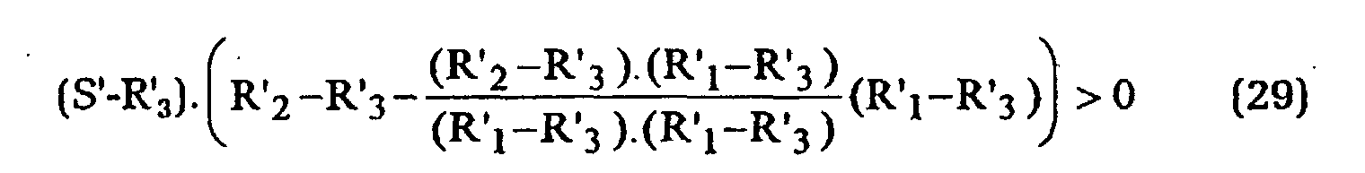
- Figure 5 illustrates the two dimensional subspace of the reference signatures with three possible locations for B. If B is inside the angle subtended by R1' and R2' (position 2), then the quality of the weld is satisfactory as far as the component B is concerned since the normalised welding signature is expected to move between R1' and R2' during normal welding as conditions change. However of B is in either of positions 1 or 3, this represents a discrepancy from ideal in addition to the discrepancy associated with non-zero C. Using the fact that the adjusted region populations making up the signatures are never negative, the condition that B lies between R1' and R2' can be written
- If this condition is satisfied then C gives the part of the measured signature which differs from the reference signatures and the quality q becomes
- Conversely, if the above conditions are not both satisfied, then either R1' or R2' will be closest to S' and the quality q should be taken as the larger of R1'.S' and R2'.S'. These are the same values as would result from using a single reference of R1 or R2 respectively.
- The above considerations can be extended to a three-reference system, R1, R2, and R3. The component of S' in the three-dimensional subspace generated by R1, R2, and R3 is
- Again the component of S' orthogonal to the subspace is C=S'-B. An approximate set of conditions for vector B' to lie within the solid region formed by R1, R2, and R3 isand
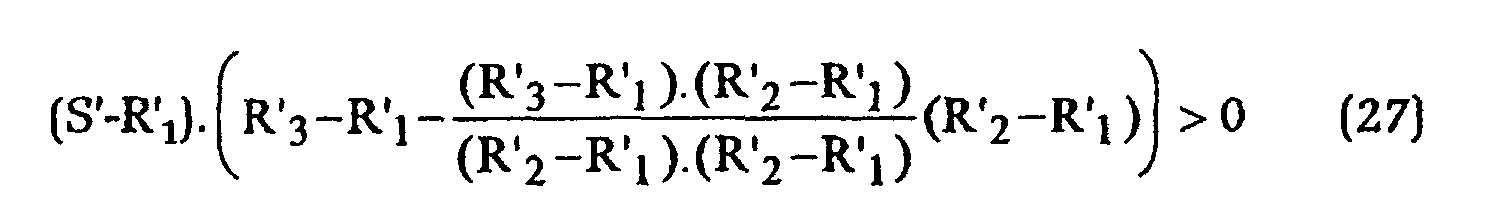 and
and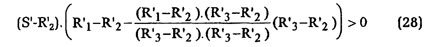
- If these conditions are all satisfied then the quality q is given by
- Conversely, if the three conditions are not all satisfied then the quality should be calculated successively for the three pairs of references R1 and R2 ; R2 and R3 ; and R1 and R3, using the method already defined for a pair of references. The largest of the three resultant quality estimates is taken to be the final quality.
- It will be appreciated by persons skilled in the art that numerous variations and/or modifications may be made to the invention as shown in the specific embodiments without departing from the spirit or scope of the invention as broadly described. The present embodiments are, therefore, to be considered in all respects as illustrative and not restrictive.
Claims (30)
- An apparatus for measuring the quality of a weld, comprising:sampling means to sample either the welding current or the welding voltage to provide a series of values for a first signal;a second sampling means to sample the welding voltage or the welding current, whichever is not sampled by the sampling means, to provide a series of values for a second signal;collection means to collect pairs of values of the first and second signals which are useful for quality monitoring into groups;calculation means to multiply values of the two dimensional group populations for each group by a weighting factor and to sum the products for each group;memory means to store a reference set of the resultant adjusted group populations collected for a high quality weldment; andcomparison means to compare the reference set of adjusted group populations with another set produced by the calculation means to provide a measure of weld quality for the weld from which the other set was produced.
- An apparatus for measuring the quality of a weld, comprising:sampling means to sample either the welding current or the welding voltage to provide a series of values for a first signal;a signal generating means to use the first signal to generate a series of values for an artificial second signal, which depends upon at least some values of the first signal either explicitly or through a recurrence relation;collection means to collect pairs of values of the first and second signals which are useful for quality monitoring into groups;calculation means to multiply values of the two dimensional group populations for each group by a weighting factor and to sum the products for each group;memory means to store a reference set of the resultant adjusted group populations collected for a high quality weldment; andcomparison means to compare the reference set of adjusted group populations with another set produced by the calculation means to provide a measure of weld quality for the weld from which the other set was produced.
- Apparatus according to claim 2, wherein the values An of the artificial signal are given by
- An apparatus according to claim 2, wherein the values An of the artificial signal are given by:
- An apparatus according to claim 2, wherein the values An of the artificial signal are given by:
- An apparatus according to any preceding claim, wherein the groups of pairs collected by the collection means are those that fall within selected regions of a two dimensional histogram of the values of the first and second signals.
- An apparatus according to claim 6, wherein the regions are not of equal size.
- An apparatus according to claim 7, wherein the regions are smaller where the density of sample points is greater.
- An apparatus according to any one of claims 6, 7 or 8, wherein the regions selected are those having the greatest density of sample points.
- An apparatus according to claim 1 or 2, wherein the calculation means sums the group population densities fq weighted by weighting factors wqr for a set of m regions to produce a set of weighted group populations G1, G2 to Gm according to:

- An apparatus according claim 10, wherein the calculation means also applies a monotonic single-valued function F to each of the Gr values to produce the set of values P1, P2 to Pm according to:
- An apparatus according to claim 11, wherein the comparison means compares a welding signature produced from a reference set of weighted group populations with a welding signature produced from another set.
- An apparatus according to claim 12, wherein there is a single reference signature R, a welding signature S of a weld and a quality factor q of the weld is defined to beand aj and bj are the Pr of the signatures A and B respectively.
- An apparatus according to claim 12, wherein there are two reference signatures R1 and R2, a welding signature S of a weld and a quality factor q of the weld is defined as follows
a normalised or unit signature U' is calculated from any signature U asand aj and bj are the Pr of the signatures A and B respectively,
P will be nonzero provided R1 and R2 are independent signatures, that is, not the same signature or signatures whose elements, the adjusted region populations, differ from each other by a constant multiplying factor;
P' and R1' are orthogonal unit signatures in the two-dimensional linear signature subspace defined by R1 and R2, and the component B of S' which lies in the subspace is - An apparatus according to claim 12, wherein there are three reference signatures R1, R2 and R3, a welding signature S of a weld and a quality factor q of the weld is defined as follows
a normalised or unit signature U' is calculated from any signature U asand aj and bj are the Pr of the signatures A and B respectively,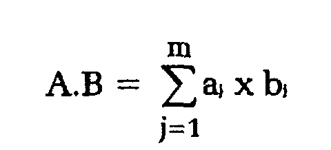
the component of S' in the three-dimensional subspace generated by R1, R2, and R3 isand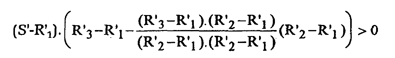 and
and if these conditions are all satisfied then the quality q is given by
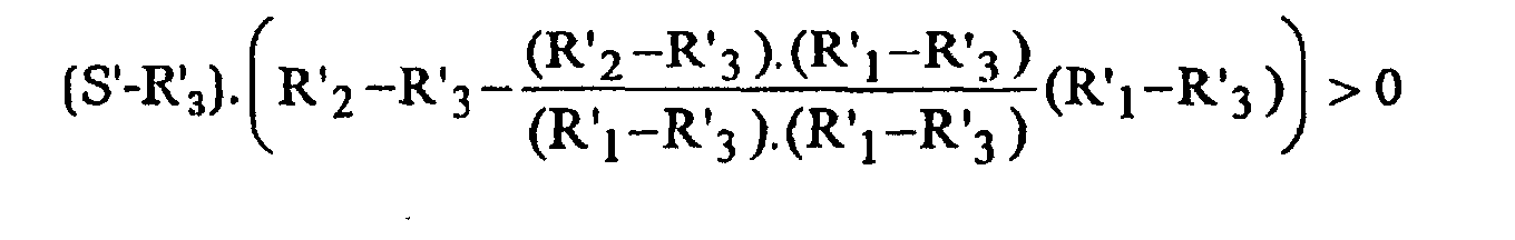
- A method of measuring weld quality comprising the steps of:sampling either the welding current or the welding voltage to provide a series of values for a first signal;sampling the welding voltage or the welding current, whichever has not already been sampled, to provide a series of values for a second signal;pairing corresponding values of the first and second signals.collecting pairs of values which are useful for quality monitoring into groups;calculating the products of the two dimensional group populations with fixed weights defined for the same groups and summing the products for each group to produce a new set of weighted group populations;storing a reference set of adjusted group populations obtained from producing a high quality weldment, or, alternatively, determining a reference set from a weighted average of sets of adjusted group populations calculated previously; andcomparing the reference set of adjusted group populations with another set to produce a measure of weld quality for the weld from which the other set was produced.
- A method of measuring weld quality comprising the steps of:sampling either the welding current or the welding voltage to provide a series of values for a first signal;generating a series of values for an artificial second signal, which depends upon at least some values of the first signal either explicitly or through a recurrence relation;pairing corresponding values of the first and second signals.collecting pairs of values which are useful for quality monitoring into groups;calculating the products of the two dimensional group populations with fixed weights defined for the same groups and summing the products for each group to produce a new set of weighted group populations;storing a reference set of adjusted group populations obtained from producing a high quality weldment, or, alternatively, determining a reference set from a weighted average of sets of adjusted group populations calculated previously; andcomparing the reference set of adjusted group populations with another set to produce a measure of weld quality for the weld from which the other set was produced.
- A method according to claim 17, wherein the values An of the artificial signal are given by:
- A method according to claim 17, wherein the values An of the artificial signal are given by:
- A method according to claim 17, wherein the values An of the artificial signal are given by:
- A method according to any one of claims 16 to 20, wherein the groups of pairs collected by the collection means are those that fall within selected regions of a two dimensional histogram of the values of the first and second signals.
- A method according to claim 21, wherein the regions are not of equal size.
- A method according to claim 22, wherein the regions are smaller where the density of sample points is greater.
- A method according to any one of claims 21, 22 or 23, wherein the regions selected are those having the greatest density of sample points.
- A method according to claim 16 or 17, wherein the calculating step sums the group population densities fq weighted by weighting factors wqr for a set of m groups to produce a set of weighted group populations, according to:

- A method according to claim 25, wherein the calculating step also applies a fixed monotonic single valued function F to each of the weighted group populations Gr to produce a new set of adjusted group populations Pr, according to:
- A method according to claim 26, wherein the comparing step compares a welding signature produced from the reference set of adjusted group populations with a welding signature produced from another set.
- A method according to claim 27, wherein there is a single reference signature R, a welding signature Sof a weld and a quality factor q of the weld is defined to bewhere aj and bj are the adjusted region populations of the signatures A and B respectively.

- An method according to claim 27, wherein there are two reference signatures R1 and R2, a welding signature S of a weld and a quality factor q of the weld is defined as follows
a normalised or unit signature U' is calculated from any signature U asand aj and bj are the Pr of the signatures A and B respectively,
P will be nonzero provided R1 and R2 are independent signatures, that is, not the same signature or signatures whose elements, the adjusted region populations, differ from each other by a constant multiplying factor;
P' and R1' are orthogonal unit signatures in the two-dimensional linear signature subspace defined by R1 and R2, and the component B of S' which lies in the subspace is - An method according to claim 27, wherein there are three reference signatures R1, R2 and R3, a welding signature S of a weld and a quality factor q of the weld is defined as follows
a normalised or unit signature U1 is calculated from any signature U asand aj and bj are the Pr of the signatures A and B respectively,
the component of S' in the three-dimensional subspace generated by R1, R2, and R3 isand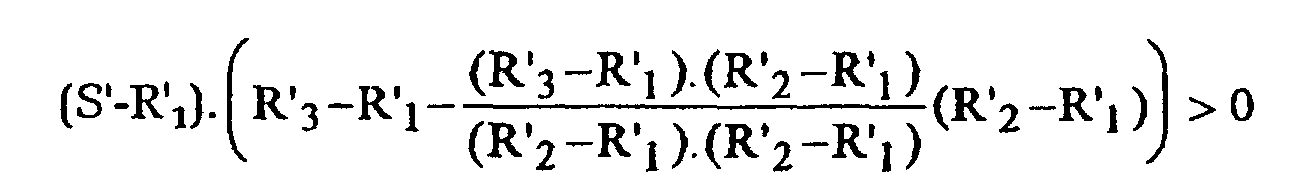 and
and if these conditions are all satisfied then the quality q is given by
Applications Claiming Priority (3)
| Application Number | Priority Date | Filing Date | Title |
|---|---|---|---|
| AUPO607397 | 1997-04-08 | ||
| AUPO6073A AUPO607397A0 (en) | 1997-04-08 | 1997-04-08 | Weld quality measurement |
| PCT/AU1998/000244 WO1998045078A1 (en) | 1997-04-08 | 1998-04-08 | Weld quality measurement |
Publications (3)
| Publication Number | Publication Date |
|---|---|
| EP1007263A1 EP1007263A1 (en) | 2000-06-14 |
| EP1007263A4 EP1007263A4 (en) | 2001-11-21 |
| EP1007263B1 true EP1007263B1 (en) | 2003-09-17 |
Family
ID=3800372
Family Applications (1)
| Application Number | Title | Priority Date | Filing Date |
|---|---|---|---|
| EP98913436A Expired - Lifetime EP1007263B1 (en) | 1997-04-08 | 1998-04-08 | Weld quality measurement |
Country Status (11)
| Country | Link |
|---|---|
| US (1) | US6288364B1 (en) |
| EP (1) | EP1007263B1 (en) |
| KR (1) | KR100503778B1 (en) |
| AT (1) | ATE249906T1 (en) |
| AU (1) | AUPO607397A0 (en) |
| CA (1) | CA2285561C (en) |
| DE (1) | DE69818275T2 (en) |
| DK (1) | DK1007263T3 (en) |
| ES (1) | ES2202826T3 (en) |
| PT (1) | PT1007263E (en) |
| WO (1) | WO1998045078A1 (en) |
Families Citing this family (48)
| Publication number | Priority date | Publication date | Assignee | Title |
|---|---|---|---|---|
| US6660965B2 (en) * | 1999-12-15 | 2003-12-09 | The University Of Sydney | Welding assessment |
| AU763689B2 (en) * | 1999-12-15 | 2003-07-31 | University Of Sydney, The | Welding assessment |
| US6441342B1 (en) * | 2000-11-20 | 2002-08-27 | Lincoln Global, Inc. | Monitor for electric arc welder |
| KR100428050B1 (en) * | 2001-06-25 | 2004-04-28 | 한국과학기술원 | Weld quality assessment method of arc welding |
| JP4667678B2 (en) * | 2001-09-20 | 2011-04-13 | 中央精機株式会社 | Arc welding quality evaluation system |
| DE10204495C1 (en) * | 2002-02-04 | 2003-07-03 | Tech Fachhochschule Wildau | Test apparatus for welding current power supply units, comprises enclosed non-sacrificial electrodes with instrument measuring their separation and other arc parameters |
| US6670574B1 (en) * | 2002-07-31 | 2003-12-30 | Unitek Miyachi Corporation | Laser weld monitor |
| DE102006038786A1 (en) | 2006-08-18 | 2008-02-21 | Robert Bosch Gmbh | Control of a welding device |
| US9104195B2 (en) | 2006-12-20 | 2015-08-11 | Lincoln Global, Inc. | Welding job sequencer |
| US10994358B2 (en) | 2006-12-20 | 2021-05-04 | Lincoln Global, Inc. | System and method for creating or modifying a welding sequence based on non-real world weld data |
| US9937577B2 (en) | 2006-12-20 | 2018-04-10 | Lincoln Global, Inc. | System for a welding sequencer |
| US8851896B2 (en) | 2008-08-21 | 2014-10-07 | Lincoln Global, Inc. | Virtual reality GTAW and pipe welding simulator and setup |
| US8911237B2 (en) | 2008-08-21 | 2014-12-16 | Lincoln Global, Inc. | Virtual reality pipe welding simulator and setup |
| US9483959B2 (en) | 2008-08-21 | 2016-11-01 | Lincoln Global, Inc. | Welding simulator |
| US9318026B2 (en) | 2008-08-21 | 2016-04-19 | Lincoln Global, Inc. | Systems and methods providing an enhanced user experience in a real-time simulated virtual reality welding environment |
| US9330575B2 (en) | 2008-08-21 | 2016-05-03 | Lincoln Global, Inc. | Tablet-based welding simulator |
| US9196169B2 (en) | 2008-08-21 | 2015-11-24 | Lincoln Global, Inc. | Importing and analyzing external data using a virtual reality welding system |
| US8884177B2 (en) | 2009-11-13 | 2014-11-11 | Lincoln Global, Inc. | Systems, methods, and apparatuses for monitoring weld quality |
| US9280913B2 (en) | 2009-07-10 | 2016-03-08 | Lincoln Global, Inc. | Systems and methods providing enhanced education and training in a virtual reality environment |
| US8834168B2 (en) | 2008-08-21 | 2014-09-16 | Lincoln Global, Inc. | System and method providing combined virtual reality arc welding and three-dimensional (3D) viewing |
| US8274013B2 (en) | 2009-03-09 | 2012-09-25 | Lincoln Global, Inc. | System for tracking and analyzing welding activity |
| US9221117B2 (en) | 2009-07-08 | 2015-12-29 | Lincoln Global, Inc. | System for characterizing manual welding operations |
| US9773429B2 (en) | 2009-07-08 | 2017-09-26 | Lincoln Global, Inc. | System and method for manual welder training |
| US10748447B2 (en) | 2013-05-24 | 2020-08-18 | Lincoln Global, Inc. | Systems and methods providing a computerized eyewear device to aid in welding |
| US9011154B2 (en) | 2009-07-10 | 2015-04-21 | Lincoln Global, Inc. | Virtual welding system |
| US8569655B2 (en) | 2009-10-13 | 2013-10-29 | Lincoln Global, Inc. | Welding helmet with integral user interface |
| US9468988B2 (en) | 2009-11-13 | 2016-10-18 | Lincoln Global, Inc. | Systems, methods, and apparatuses for monitoring weld quality |
| US8569646B2 (en) * | 2009-11-13 | 2013-10-29 | Lincoln Global, Inc. | Systems, methods, and apparatuses for monitoring weld quality |
| CA2821671C (en) | 2010-12-13 | 2018-01-09 | Edison Welding Institute, Inc. | Welding training system |
| US20160093233A1 (en) | 2012-07-06 | 2016-03-31 | Lincoln Global, Inc. | System for characterizing manual welding operations on pipe and other curved structures |
| US9767712B2 (en) | 2012-07-10 | 2017-09-19 | Lincoln Global, Inc. | Virtual reality pipe welding simulator and setup |
| US10930174B2 (en) | 2013-05-24 | 2021-02-23 | Lincoln Global, Inc. | Systems and methods providing a computerized eyewear device to aid in welding |
| US20150072323A1 (en) | 2013-09-11 | 2015-03-12 | Lincoln Global, Inc. | Learning management system for a real-time simulated virtual reality welding training environment |
| US10083627B2 (en) | 2013-11-05 | 2018-09-25 | Lincoln Global, Inc. | Virtual reality and real welding training system and method |
| US9836987B2 (en) | 2014-02-14 | 2017-12-05 | Lincoln Global, Inc. | Virtual reality pipe welding simulator and setup |
| WO2015185972A1 (en) | 2014-06-02 | 2015-12-10 | Lincoln Global, Inc. | System and method for manual welder training |
| DE102015114957A1 (en) * | 2015-09-07 | 2017-03-09 | Harms + Wende Gmbh & Co. Kg | Electric welding process |
| CN105750754B (en) * | 2016-05-06 | 2018-01-16 | 广州市精源电子设备有限公司 | Resistance spot welding quality influence factor discrimination method and system |
| EP3319066A1 (en) | 2016-11-04 | 2018-05-09 | Lincoln Global, Inc. | Magnetic frequency selection for electromagnetic position tracking |
| US20180130226A1 (en) | 2016-11-07 | 2018-05-10 | Lincoln Global, Inc. | System and method for calibrating a welding trainer |
| US10913125B2 (en) | 2016-11-07 | 2021-02-09 | Lincoln Global, Inc. | Welding system providing visual and audio cues to a welding helmet with a display |
| US10997872B2 (en) | 2017-06-01 | 2021-05-04 | Lincoln Global, Inc. | Spring-loaded tip assembly to support simulated shielded metal arc welding |
| US11475792B2 (en) | 2018-04-19 | 2022-10-18 | Lincoln Global, Inc. | Welding simulator with dual-user configuration |
| US11557223B2 (en) | 2018-04-19 | 2023-01-17 | Lincoln Global, Inc. | Modular and reconfigurable chassis for simulated welding training |
| CN118891521A (en) * | 2021-12-22 | 2024-11-01 | 卡文迪什核电有限公司 | Improvements in welding and quality control and related improvements |
| GB2616336A (en) * | 2021-12-22 | 2023-09-06 | Cavendish Nuclear Ltd | Improvements in and relating to welding and quality control |
| DE102022208184A1 (en) * | 2022-08-05 | 2024-02-08 | Kjellberg Stiftung, rechtsfähige Stiftung des bürgerlichen Rechts | Method and device for detecting a process state of a plasma arc process |
| CN118671145B (en) * | 2024-08-14 | 2024-10-22 | 天津商科数控技术股份有限公司 | Welding quality detection method, device, equipment and storage medium |
Family Cites Families (11)
| Publication number | Priority date | Publication date | Assignee | Title |
|---|---|---|---|---|
| US4024371A (en) * | 1974-12-18 | 1977-05-17 | Kelsey-Hayes Company | Welding monitoring and control system |
| HU188832B (en) * | 1983-01-26 | 1986-05-28 | Retfalvi,Ferenc,Hu | Method and apparatus for securing the weld quality during operation, for marking the defect spots on piece and for certifying the quality |
| JPH0815669B2 (en) * | 1988-07-06 | 1996-02-21 | 日本電装株式会社 | Control device for resistance welding |
| DE3936329A1 (en) | 1989-10-27 | 1991-05-08 | Innovationsgesellschaft Fuer F | METHOD FOR AUTOMATICALLY DETERMINING PARAMETERS FOR PROCESS CONTROL SYSTEMS WITH UNKNOWN TRANSFER BEHAVIOR, ESPECIALLY FOR PROCESS CONTROL SYSTEMS FOR RESISTANCE SPOT WELDING, AND DEVICE FOR CARRYING OUT THE PROCESS |
| US5270516A (en) | 1991-04-01 | 1993-12-14 | Matsushita Electric Industrial Co., Ltd. | Arc welding machine |
| FR2694899B1 (en) | 1992-08-19 | 1994-09-23 | Paul Leon | Process for measuring a quantity representative of a physical and / or mechanical characteristic of a spot weld, applications of this process to spot welding. |
| JP3322448B2 (en) * | 1993-07-16 | 2002-09-09 | 小原株式会社 | Resistance welding control method |
| DE4330914A1 (en) | 1993-09-11 | 1995-03-23 | Bosch Gmbh Robert | Resistance welding process |
| JPH07303966A (en) * | 1994-05-11 | 1995-11-21 | Fanuc Ltd | Robot control device |
| US5521354A (en) * | 1994-06-21 | 1996-05-28 | Caterpillar Inc. | Method for arc welding fault detection |
| DE19539038A1 (en) | 1995-10-20 | 1997-04-24 | Ewm High Tech Precision Schwei | Arc welder with an AC powered rectifier |
-
1997
- 1997-04-08 AU AUPO6073A patent/AUPO607397A0/en not_active Abandoned
-
1998
- 1998-04-08 US US09/402,717 patent/US6288364B1/en not_active Expired - Fee Related
- 1998-04-08 PT PT98913436T patent/PT1007263E/en unknown
- 1998-04-08 DE DE69818275T patent/DE69818275T2/en not_active Expired - Fee Related
- 1998-04-08 WO PCT/AU1998/000244 patent/WO1998045078A1/en not_active Ceased
- 1998-04-08 ES ES98913436T patent/ES2202826T3/en not_active Expired - Lifetime
- 1998-04-08 AT AT98913436T patent/ATE249906T1/en not_active IP Right Cessation
- 1998-04-08 KR KR10-1999-7009259A patent/KR100503778B1/en not_active Expired - Fee Related
- 1998-04-08 DK DK98913436T patent/DK1007263T3/en active
- 1998-04-08 EP EP98913436A patent/EP1007263B1/en not_active Expired - Lifetime
- 1998-04-08 CA CA002285561A patent/CA2285561C/en not_active Expired - Fee Related
Also Published As
| Publication number | Publication date |
|---|---|
| ATE249906T1 (en) | 2003-10-15 |
| EP1007263A1 (en) | 2000-06-14 |
| AUPO607397A0 (en) | 1997-05-01 |
| CA2285561C (en) | 2004-07-20 |
| KR20010006180A (en) | 2001-01-26 |
| KR100503778B1 (en) | 2005-07-26 |
| WO1998045078A1 (en) | 1998-10-15 |
| CA2285561A1 (en) | 1998-10-15 |
| DE69818275D1 (en) | 2003-10-23 |
| DK1007263T3 (en) | 2004-02-02 |
| EP1007263A4 (en) | 2001-11-21 |
| DE69818275T2 (en) | 2004-04-08 |
| ES2202826T3 (en) | 2004-04-01 |
| US6288364B1 (en) | 2001-09-11 |
| PT1007263E (en) | 2004-02-27 |
Similar Documents
| Publication | Publication Date | Title |
|---|---|---|
| EP1007263B1 (en) | Weld quality measurement | |
| CA2393773C (en) | Welding assessment | |
| Zhang et al. | Prediction of surface roughness in end face milling based on Gaussian process regression and cause analysis considering tool vibration | |
| JP3704336B2 (en) | Waveform detector and condition monitoring system using it | |
| CN100451895C (en) | Method for controlling quality of industry process especially of laser welding process | |
| US6064029A (en) | Apparatus for controlling the quality of a resistance spot weld and method therefor | |
| CN113916983B (en) | Device for detecting damage of scraper of powder-spreading type metal 3D printing equipment | |
| US7020046B1 (en) | System and method for target motion analysis with intelligent parameter evaluation plot | |
| CN110596541A (en) | Partial discharge positioning method and system based on fingerprint map | |
| AU741965B2 (en) | Weld quality measurement | |
| EP2003470B1 (en) | Constant false alarm rate adaptive radar control | |
| KR102793030B1 (en) | Apparatus for diagnosing unusual situation of equipment based on energy time series data and method there | |
| CN116644305B (en) | Ultrasonic welding quality prediction method based on multi-sensor data decision fusion | |
| CN100464270C (en) | Method of controlling the quality of industrial processes and system therefor | |
| Belmont et al. | Adaptive measurement and signal processing strategies associated with deterministic sea wave prediction | |
| Huang et al. | Multifractal analysis for gas metal arc welding | |
| CN120948923A (en) | A surge arrester parameter measurement system and method | |
| US20250285024A1 (en) | Method for Generating a Training Dataset | |
| AU2130101A (en) | Welding assessment | |
| US20250355053A1 (en) | Measurement apparatus, electricity storage system, and measurement method | |
| US20250284968A1 (en) | Method for Generating a Training Dataset | |
| US20250283998A1 (en) | Measuring Device | |
| US20250283999A1 (en) | Method for Operating a Measuring Device | |
| JP2607861B2 (en) | Signal format judgment method | |
| EA050181B1 (en) | METHOD OF MANUFACTURING A PRODUCT BY THREE-DIMENSIONAL PRINTING BY ELECTRIC ARC SURFACING WITH INTELLIGENT DIAGNOSTICS OF DYNAMIC STABILITY OF THE PROCESS |
Legal Events
| Date | Code | Title | Description |
|---|---|---|---|
| PUAI | Public reference made under article 153(3) epc to a published international application that has entered the european phase |
Free format text: ORIGINAL CODE: 0009012 |
|
| 17P | Request for examination filed |
Effective date: 19991025 |
|
| AK | Designated contracting states |
Kind code of ref document: A1 Designated state(s): AT BE CH CY DE DK ES FI FR GB GR IE IT LI LU MC NL PT SE |
|
| AX | Request for extension of the european patent |
Free format text: AL PAYMENT 19991025;LT PAYMENT 19991025;LV PAYMENT 19991025;MK PAYMENT 19991025;RO PAYMENT 19991025;SI PAYMENT 19991025 |
|
| A4 | Supplementary search report drawn up and despatched |
Effective date: 20011009 |
|
| AK | Designated contracting states |
Kind code of ref document: A4 Designated state(s): AT BE CH CY DE DK ES FI FR GB GR IE IT LI LU MC NL PT SE |
|
| RIC1 | Information provided on ipc code assigned before grant |
Free format text: 7B 23K 9/095 A, 7B 23K 11/25 B, 7B 23K 31/12 B |
|
| GRAH | Despatch of communication of intention to grant a patent |
Free format text: ORIGINAL CODE: EPIDOS IGRA |
|
| GRAS | Grant fee paid |
Free format text: ORIGINAL CODE: EPIDOSNIGR3 |
|
| GRAA | (expected) grant |
Free format text: ORIGINAL CODE: 0009210 |
|
| AK | Designated contracting states |
Kind code of ref document: B1 Designated state(s): AT BE CH CY DE DK ES FI FR GB GR IE IT LI LU MC NL PT SE |
|
| AX | Request for extension of the european patent |
Extension state: AL LT LV MK RO SI |
|
| PG25 | Lapsed in a contracting state [announced via postgrant information from national office to epo] |
Ref country code: CY Free format text: LAPSE BECAUSE OF FAILURE TO SUBMIT A TRANSLATION OF THE DESCRIPTION OR TO PAY THE FEE WITHIN THE PRESCRIBED TIME-LIMIT Effective date: 20030917 |
|
| REG | Reference to a national code |
Ref country code: GB Ref legal event code: FG4D |
|
| REG | Reference to a national code |
Ref country code: SE Ref legal event code: TRGR Ref country code: CH Ref legal event code: EP |
|
| REF | Corresponds to: |
Ref document number: 69818275 Country of ref document: DE Date of ref document: 20031023 Kind code of ref document: P |
|
| REG | Reference to a national code |
Ref country code: IE Ref legal event code: FG4D |
|
| PG25 | Lapsed in a contracting state [announced via postgrant information from national office to epo] |
Ref country code: GR Free format text: LAPSE BECAUSE OF FAILURE TO SUBMIT A TRANSLATION OF THE DESCRIPTION OR TO PAY THE FEE WITHIN THE PRESCRIBED TIME-LIMIT Effective date: 20031217 |
|
| REG | Reference to a national code |
Ref country code: CH Ref legal event code: NV Representative=s name: ISLER & PEDRAZZINI AG |
|
| REG | Reference to a national code |
Ref country code: DK Ref legal event code: T3 |
|
| LTIE | Lt: invalidation of european patent or patent extension |
Effective date: 20030917 |
|
| REG | Reference to a national code |
Ref country code: ES Ref legal event code: FG2A Ref document number: 2202826 Country of ref document: ES Kind code of ref document: T3 |
|
| PG25 | Lapsed in a contracting state [announced via postgrant information from national office to epo] |
Ref country code: LU Free format text: LAPSE BECAUSE OF NON-PAYMENT OF DUE FEES Effective date: 20040408 |
|
| PG25 | Lapsed in a contracting state [announced via postgrant information from national office to epo] |
Ref country code: MC Free format text: LAPSE BECAUSE OF NON-PAYMENT OF DUE FEES Effective date: 20040430 |
|
| ET | Fr: translation filed | ||
| PLBE | No opposition filed within time limit |
Free format text: ORIGINAL CODE: 0009261 |
|
| STAA | Information on the status of an ep patent application or granted ep patent |
Free format text: STATUS: NO OPPOSITION FILED WITHIN TIME LIMIT |
|
| 26N | No opposition filed |
Effective date: 20040618 |
|
| PGFP | Annual fee paid to national office [announced via postgrant information from national office to epo] |
Ref country code: NL Payment date: 20050403 Year of fee payment: 8 |
|
| PGFP | Annual fee paid to national office [announced via postgrant information from national office to epo] |
Ref country code: SE Payment date: 20050406 Year of fee payment: 8 Ref country code: PT Payment date: 20050406 Year of fee payment: 8 |
|
| PGFP | Annual fee paid to national office [announced via postgrant information from national office to epo] |
Ref country code: AT Payment date: 20050413 Year of fee payment: 8 |
|
| PGFP | Annual fee paid to national office [announced via postgrant information from national office to epo] |
Ref country code: FI Payment date: 20050414 Year of fee payment: 8 Ref country code: IE Payment date: 20050414 Year of fee payment: 8 |
|
| PGFP | Annual fee paid to national office [announced via postgrant information from national office to epo] |
Ref country code: DK Payment date: 20050415 Year of fee payment: 8 Ref country code: CH Payment date: 20050415 Year of fee payment: 8 |
|
| PGFP | Annual fee paid to national office [announced via postgrant information from national office to epo] |
Ref country code: ES Payment date: 20050527 Year of fee payment: 8 |
|
| PGFP | Annual fee paid to national office [announced via postgrant information from national office to epo] |
Ref country code: BE Payment date: 20050615 Year of fee payment: 8 |
|
| PG25 | Lapsed in a contracting state [announced via postgrant information from national office to epo] |
Ref country code: FI Free format text: LAPSE BECAUSE OF NON-PAYMENT OF DUE FEES Effective date: 20060408 Ref country code: AT Free format text: LAPSE BECAUSE OF NON-PAYMENT OF DUE FEES Effective date: 20060408 |
|
| PG25 | Lapsed in a contracting state [announced via postgrant information from national office to epo] |
Ref country code: SE Free format text: LAPSE BECAUSE OF NON-PAYMENT OF DUE FEES Effective date: 20060409 |
|
| PG25 | Lapsed in a contracting state [announced via postgrant information from national office to epo] |
Ref country code: IE Free format text: LAPSE BECAUSE OF NON-PAYMENT OF DUE FEES Effective date: 20060410 Ref country code: ES Free format text: LAPSE BECAUSE OF NON-PAYMENT OF DUE FEES Effective date: 20060410 |
|
| PG25 | Lapsed in a contracting state [announced via postgrant information from national office to epo] |
Ref country code: LI Free format text: LAPSE BECAUSE OF NON-PAYMENT OF DUE FEES Effective date: 20060430 Ref country code: CH Free format text: LAPSE BECAUSE OF NON-PAYMENT OF DUE FEES Effective date: 20060430 Ref country code: BE Free format text: LAPSE BECAUSE OF NON-PAYMENT OF DUE FEES Effective date: 20060430 |
|
| PGFP | Annual fee paid to national office [announced via postgrant information from national office to epo] |
Ref country code: IT Payment date: 20060430 Year of fee payment: 9 |
|
| PG25 | Lapsed in a contracting state [announced via postgrant information from national office to epo] |
Ref country code: DK Free format text: LAPSE BECAUSE OF NON-PAYMENT OF DUE FEES Effective date: 20060501 |
|
| PG25 | Lapsed in a contracting state [announced via postgrant information from national office to epo] |
Ref country code: PT Free format text: LAPSE BECAUSE OF NON-PAYMENT OF DUE FEES Effective date: 20061009 |
|
| PG25 | Lapsed in a contracting state [announced via postgrant information from national office to epo] |
Ref country code: NL Free format text: LAPSE BECAUSE OF NON-PAYMENT OF DUE FEES Effective date: 20061101 |
|
| REG | Reference to a national code |
Ref country code: PT Ref legal event code: MM4A Free format text: LAPSE DUE TO NON-PAYMENT OF FEES Effective date: 20061009 |
|
| REG | Reference to a national code |
Ref country code: DK Ref legal event code: EBP |
|
| REG | Reference to a national code |
Ref country code: CH Ref legal event code: PL |
|
| EUG | Se: european patent has lapsed | ||
| NLV4 | Nl: lapsed or anulled due to non-payment of the annual fee |
Effective date: 20061101 |
|
| REG | Reference to a national code |
Ref country code: IE Ref legal event code: MM4A |
|
| REG | Reference to a national code |
Ref country code: ES Ref legal event code: FD2A Effective date: 20060410 |
|
| BERE | Be: lapsed |
Owner name: THE *UNIVERSITY OF SYDNEY Effective date: 20060430 |
|
| PGFP | Annual fee paid to national office [announced via postgrant information from national office to epo] |
Ref country code: DE Payment date: 20080417 Year of fee payment: 11 |
|
| PGFP | Annual fee paid to national office [announced via postgrant information from national office to epo] |
Ref country code: FR Payment date: 20080414 Year of fee payment: 11 |
|
| PGFP | Annual fee paid to national office [announced via postgrant information from national office to epo] |
Ref country code: GB Payment date: 20080409 Year of fee payment: 11 |
|
| PG25 | Lapsed in a contracting state [announced via postgrant information from national office to epo] |
Ref country code: IT Free format text: LAPSE BECAUSE OF NON-PAYMENT OF DUE FEES Effective date: 20070408 |
|
| GBPC | Gb: european patent ceased through non-payment of renewal fee |
Effective date: 20090408 |
|
| REG | Reference to a national code |
Ref country code: FR Ref legal event code: ST Effective date: 20091231 |
|
| PG25 | Lapsed in a contracting state [announced via postgrant information from national office to epo] |
Ref country code: DE Free format text: LAPSE BECAUSE OF NON-PAYMENT OF DUE FEES Effective date: 20091103 |
|
| PG25 | Lapsed in a contracting state [announced via postgrant information from national office to epo] |
Ref country code: GB Free format text: LAPSE BECAUSE OF NON-PAYMENT OF DUE FEES Effective date: 20090408 Ref country code: FR Free format text: LAPSE BECAUSE OF NON-PAYMENT OF DUE FEES Effective date: 20091222 |