EP1006036B1 - Spring system for a railway vehicle - Google Patents
Spring system for a railway vehicle Download PDFInfo
- Publication number
- EP1006036B1 EP1006036B1 EP99122820A EP99122820A EP1006036B1 EP 1006036 B1 EP1006036 B1 EP 1006036B1 EP 99122820 A EP99122820 A EP 99122820A EP 99122820 A EP99122820 A EP 99122820A EP 1006036 B1 EP1006036 B1 EP 1006036B1
- Authority
- EP
- European Patent Office
- Prior art keywords
- spring arrangement
- arrangement according
- measuring
- spring
- sensor
- Prior art date
- Legal status (The legal status is an assumption and is not a legal conclusion. Google has not performed a legal analysis and makes no representation as to the accuracy of the status listed.)
- Expired - Lifetime
Links
Images
Classifications
-
- B—PERFORMING OPERATIONS; TRANSPORTING
- B60—VEHICLES IN GENERAL
- B60G—VEHICLE SUSPENSION ARRANGEMENTS
- B60G17/00—Resilient suspensions having means for adjusting the spring or vibration-damper characteristics, for regulating the distance between a supporting surface and a sprung part of vehicle or for locking suspension during use to meet varying vehicular or surface conditions, e.g. due to speed or load
- B60G17/015—Resilient suspensions having means for adjusting the spring or vibration-damper characteristics, for regulating the distance between a supporting surface and a sprung part of vehicle or for locking suspension during use to meet varying vehicular or surface conditions, e.g. due to speed or load the regulating means comprising electric or electronic elements
- B60G17/018—Resilient suspensions having means for adjusting the spring or vibration-damper characteristics, for regulating the distance between a supporting surface and a sprung part of vehicle or for locking suspension during use to meet varying vehicular or surface conditions, e.g. due to speed or load the regulating means comprising electric or electronic elements characterised by the use of a specific signal treatment or control method
- B60G17/0185—Resilient suspensions having means for adjusting the spring or vibration-damper characteristics, for regulating the distance between a supporting surface and a sprung part of vehicle or for locking suspension during use to meet varying vehicular or surface conditions, e.g. due to speed or load the regulating means comprising electric or electronic elements characterised by the use of a specific signal treatment or control method for failure detection
-
- B—PERFORMING OPERATIONS; TRANSPORTING
- B60—VEHICLES IN GENERAL
- B60G—VEHICLE SUSPENSION ARRANGEMENTS
- B60G17/00—Resilient suspensions having means for adjusting the spring or vibration-damper characteristics, for regulating the distance between a supporting surface and a sprung part of vehicle or for locking suspension during use to meet varying vehicular or surface conditions, e.g. due to speed or load
- B60G17/005—Suspension locking arrangements
-
- B—PERFORMING OPERATIONS; TRANSPORTING
- B60—VEHICLES IN GENERAL
- B60G—VEHICLE SUSPENSION ARRANGEMENTS
- B60G17/00—Resilient suspensions having means for adjusting the spring or vibration-damper characteristics, for regulating the distance between a supporting surface and a sprung part of vehicle or for locking suspension during use to meet varying vehicular or surface conditions, e.g. due to speed or load
- B60G17/015—Resilient suspensions having means for adjusting the spring or vibration-damper characteristics, for regulating the distance between a supporting surface and a sprung part of vehicle or for locking suspension during use to meet varying vehicular or surface conditions, e.g. due to speed or load the regulating means comprising electric or electronic elements
- B60G17/019—Resilient suspensions having means for adjusting the spring or vibration-damper characteristics, for regulating the distance between a supporting surface and a sprung part of vehicle or for locking suspension during use to meet varying vehicular or surface conditions, e.g. due to speed or load the regulating means comprising electric or electronic elements characterised by the type of sensor or the arrangement thereof
- B60G17/01933—Velocity, e.g. relative velocity-displacement sensors
-
- B—PERFORMING OPERATIONS; TRANSPORTING
- B60—VEHICLES IN GENERAL
- B60G—VEHICLE SUSPENSION ARRANGEMENTS
- B60G17/00—Resilient suspensions having means for adjusting the spring or vibration-damper characteristics, for regulating the distance between a supporting surface and a sprung part of vehicle or for locking suspension during use to meet varying vehicular or surface conditions, e.g. due to speed or load
- B60G17/02—Spring characteristics, e.g. mechanical springs and mechanical adjusting means
- B60G17/04—Spring characteristics, e.g. mechanical springs and mechanical adjusting means fluid spring characteristics
- B60G17/052—Pneumatic spring characteristics
-
- B—PERFORMING OPERATIONS; TRANSPORTING
- B61—RAILWAYS
- B61F—RAIL VEHICLE SUSPENSIONS, e.g. UNDERFRAMES, BOGIES OR ARRANGEMENTS OF WHEEL AXLES; RAIL VEHICLES FOR USE ON TRACKS OF DIFFERENT WIDTH; PREVENTING DERAILING OF RAIL VEHICLES; WHEEL GUARDS, OBSTRUCTION REMOVERS OR THE LIKE FOR RAIL VEHICLES
- B61F5/00—Constructional details of bogies; Connections between bogies and vehicle underframes; Arrangements or devices for adjusting or allowing self-adjustment of wheel axles or bogies when rounding curves
- B61F5/02—Arrangements permitting limited transverse relative movements between vehicle underframe or bolster and bogie; Connections between underframes and bogies
- B61F5/14—Side bearings
-
- F—MECHANICAL ENGINEERING; LIGHTING; HEATING; WEAPONS; BLASTING
- F16—ENGINEERING ELEMENTS AND UNITS; GENERAL MEASURES FOR PRODUCING AND MAINTAINING EFFECTIVE FUNCTIONING OF MACHINES OR INSTALLATIONS; THERMAL INSULATION IN GENERAL
- F16F—SPRINGS; SHOCK-ABSORBERS; MEANS FOR DAMPING VIBRATION
- F16F9/00—Springs, vibration-dampers, shock-absorbers, or similarly-constructed movement-dampers using a fluid or the equivalent as damping medium
- F16F9/02—Springs, vibration-dampers, shock-absorbers, or similarly-constructed movement-dampers using a fluid or the equivalent as damping medium using gas only or vacuum
- F16F9/04—Springs, vibration-dampers, shock-absorbers, or similarly-constructed movement-dampers using a fluid or the equivalent as damping medium using gas only or vacuum in a chamber with a flexible wall
- F16F9/05—Springs, vibration-dampers, shock-absorbers, or similarly-constructed movement-dampers using a fluid or the equivalent as damping medium using gas only or vacuum in a chamber with a flexible wall the flexible wall being of the rolling diaphragm type
- F16F9/052—Springs, vibration-dampers, shock-absorbers, or similarly-constructed movement-dampers using a fluid or the equivalent as damping medium using gas only or vacuum in a chamber with a flexible wall the flexible wall being of the rolling diaphragm type characterised by the bumper
-
- B—PERFORMING OPERATIONS; TRANSPORTING
- B60—VEHICLES IN GENERAL
- B60G—VEHICLE SUSPENSION ARRANGEMENTS
- B60G2202/00—Indexing codes relating to the type of spring, damper or actuator
- B60G2202/10—Type of spring
- B60G2202/15—Fluid spring
- B60G2202/152—Pneumatic spring
-
- B—PERFORMING OPERATIONS; TRANSPORTING
- B60—VEHICLES IN GENERAL
- B60G—VEHICLE SUSPENSION ARRANGEMENTS
- B60G2204/00—Indexing codes related to suspensions per se or to auxiliary parts
- B60G2204/10—Mounting of suspension elements
- B60G2204/11—Mounting of sensors thereon
- B60G2204/111—Mounting of sensors thereon on pneumatic springs
-
- B—PERFORMING OPERATIONS; TRANSPORTING
- B60—VEHICLES IN GENERAL
- B60G—VEHICLE SUSPENSION ARRANGEMENTS
- B60G2204/00—Indexing codes related to suspensions per se or to auxiliary parts
- B60G2204/10—Mounting of suspension elements
- B60G2204/12—Mounting of springs or dampers
- B60G2204/126—Mounting of pneumatic springs
-
- B—PERFORMING OPERATIONS; TRANSPORTING
- B60—VEHICLES IN GENERAL
- B60G—VEHICLE SUSPENSION ARRANGEMENTS
- B60G2204/00—Indexing codes related to suspensions per se or to auxiliary parts
- B60G2204/40—Auxiliary suspension parts; Adjustment of suspensions
- B60G2204/45—Stops limiting travel
-
- B—PERFORMING OPERATIONS; TRANSPORTING
- B60—VEHICLES IN GENERAL
- B60G—VEHICLE SUSPENSION ARRANGEMENTS
- B60G2204/00—Indexing codes related to suspensions per se or to auxiliary parts
- B60G2204/40—Auxiliary suspension parts; Adjustment of suspensions
- B60G2204/45—Stops limiting travel
- B60G2204/4502—Stops limiting travel using resilient buffer
-
- B—PERFORMING OPERATIONS; TRANSPORTING
- B60—VEHICLES IN GENERAL
- B60G—VEHICLE SUSPENSION ARRANGEMENTS
- B60G2204/00—Indexing codes related to suspensions per se or to auxiliary parts
- B60G2204/40—Auxiliary suspension parts; Adjustment of suspensions
- B60G2204/46—Means for locking the suspension
-
- B—PERFORMING OPERATIONS; TRANSPORTING
- B60—VEHICLES IN GENERAL
- B60G—VEHICLE SUSPENSION ARRANGEMENTS
- B60G2300/00—Indexing codes relating to the type of vehicle
- B60G2300/10—Railway vehicles
-
- B—PERFORMING OPERATIONS; TRANSPORTING
- B60—VEHICLES IN GENERAL
- B60G—VEHICLE SUSPENSION ARRANGEMENTS
- B60G2400/00—Indexing codes relating to detected, measured or calculated conditions or factors
- B60G2400/25—Stroke; Height; Displacement
- B60G2400/252—Stroke; Height; Displacement vertical
-
- B—PERFORMING OPERATIONS; TRANSPORTING
- B60—VEHICLES IN GENERAL
- B60G—VEHICLE SUSPENSION ARRANGEMENTS
- B60G2401/00—Indexing codes relating to the type of sensors based on the principle of their operation
- B60G2401/17—Magnetic/Electromagnetic
-
- B—PERFORMING OPERATIONS; TRANSPORTING
- B60—VEHICLES IN GENERAL
- B60G—VEHICLE SUSPENSION ARRANGEMENTS
- B60G2401/00—Indexing codes relating to the type of sensors based on the principle of their operation
- B60G2401/20—Switches, e.g. mercury or ball type switches
-
- B—PERFORMING OPERATIONS; TRANSPORTING
- B60—VEHICLES IN GENERAL
- B60G—VEHICLE SUSPENSION ARRANGEMENTS
- B60G2600/00—Indexing codes relating to particular elements, systems or processes used on suspension systems or suspension control systems
- B60G2600/08—Failure or malfunction detecting means
-
- B—PERFORMING OPERATIONS; TRANSPORTING
- B60—VEHICLES IN GENERAL
- B60G—VEHICLE SUSPENSION ARRANGEMENTS
- B60G2800/00—Indexing codes relating to the type of movement or to the condition of the vehicle and to the end result to be achieved by the control action
- B60G2800/20—Stationary vehicle
-
- B—PERFORMING OPERATIONS; TRANSPORTING
- B60—VEHICLES IN GENERAL
- B60G—VEHICLE SUSPENSION ARRANGEMENTS
- B60G2800/00—Indexing codes relating to the type of movement or to the condition of the vehicle and to the end result to be achieved by the control action
- B60G2800/20—Stationary vehicle
- B60G2800/204—Stationary vehicle adjusting floor height to the loading ramp level
- B60G2800/2042—Stationary vehicle adjusting floor height to the loading ramp level using an anticreep mechanism to lock the height
-
- B—PERFORMING OPERATIONS; TRANSPORTING
- B60—VEHICLES IN GENERAL
- B60G—VEHICLE SUSPENSION ARRANGEMENTS
- B60G2800/00—Indexing codes relating to the type of movement or to the condition of the vehicle and to the end result to be achieved by the control action
- B60G2800/80—Detection or control after a system or component failure
Definitions
- the invention relates to a suspension for a rail vehicle with at least one spring device, in particular an air spring, and with a relative to the chassis frame height adjustable stored emergency pad on which the car body of the rail vehicle decreases when the spring device fails.
- Such a spring system is for example from the Austrian Utility Model 2471 or DE29813031 U known.
- an emergency spring allows the emergency rest there shown in the form of a height-adjustable Hydraulic stamp also in emergency operation, a height adjustment of the chassis opposite the car body of the rail vehicle.
- Rail vehicles especially articulated trains, an advantage, you can namely the under the emergency conditions of the individual chassis or chassis sides Allow spaces to communicate for the hydraulic fluid.
- Hydraulic fluid column from left to right or from front to rear on the vehicle longitudinal direction possible. So the emergency edition is not perfect rigid and you can run over the hills and crests with the vehicle, even when the main spring, in particular an air spring, has failed.
- a height adjustment of the emergency pad for rail vehicles low be, for example, to adapt to the currently driven speed.
- the object of the invention is therefore to provide an improved suspension of the above to create the aforementioned genus. This task is done by the features of claim 1 solved.
- electrical signal can then be adjusted the Notauflage in their height, at a preferred embodiment, for example by supply or discharge of Hydraulic fluid under a hydraulic ram on which the emergency pad is formed is.
- Hydraulic fluid under a hydraulic ram on which the emergency pad is formed is.
- electromechanical for the emergency edition quite conceivable and possible.
- the measuring device As far as the measuring device itself is concerned, it is convenient not to directly contact the sensors the emergency rest, but a mechanical sensor to use, which is moved mechanically with the emergency rest. It can then a place cheaper place the position of the probe by means of at least one Sensor are detected, which also knows the location of the emergency.
- the axially displaceable in one sleeve-shaped guide is mounted, wherein the sensors on the sleeve-shaped Leadership can be attached.
- the measuring pin can, for example, at the Abut the underside of the piston of a hydraulic ram and thus its vertical Join in the movement.
- the measuring device according to the invention in particular in the form of a sleeve guided Meßconfigres can be easily retrofitted to existing suspension systems be there to increase the positional accuracy of the emergency pad.
- the existing oil supply port can be used to insert the sensor inside.
- the pin may be hollow to allow passage of the hydraulic oil.
- the sleeve may be connected to the housing of the spring system, for example be screwed.
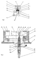
- Fig. 1 is 1 of the car body of the Rail vehicle indicated.
- the chassis frame of a not shown to resilient suspension carries the reference numeral 2. It is about the car body. 1bondedfedem against the chassis frame 2, which is mainly on the air spring 3 happens in the interior of which in normal operation via a filling opening. 5 filled compressed air is located.
- a height adjustable emergency 6 provided, which in the present embodiment on a hydraulic ram. 7 is trained.
- This hydraulic ram has a piston 8 at the bottom, whose Bottom 8a acted upon against the action of a spring 9 with hydraulic fluid is present in the space 10 by means of a schematically indicated pressure pump is.
- the pressure of the hydraulic fluid the height of the emergency rest 6 can be adjusted become. This is in principle also without measuring device, which in the following is possible, if one acts on the piston 8 from above Forces, in particular the force of the spring 9 and the compressed air and on the other hand the Oil pressure knows.
- the invention now proposes a separate Device before, to accurately detect the altitude of the emergency 6.
- Fig. 1 is in the measuring device around one connected to the underside 8a of the piston 8 or pressed against it Measuring pin 12, the 13 readable by sensors 13 marks.
- the exits This example, inductive proximity sensors are equipped with an evaluation device 15 connected via the pressure pump 11 and the pressure of the hydraulic fluid Adjust the altitude of the emergency rest 6 to a predetermined level.
- only two sensors 13 are shown, whereby a Einregelung on a certain altitude between the two sensors altitude of the emergency pad. 6 is possible.
- there are also several sensors or one sensor line As well as continuously detecting sensors conceivable and possible to the altitude of the Emergency stop 6 to be set to any value.
- Fig. 2 shows another embodiment, which is substantially the lower Part of Fig. 1 corresponds.
- the altitude of the piston 8 relative to the Housing 16 mirrors exactly the altitude of the overlying Notauflage (in Fig. 2 not shown) again. It is therefore about to detect the altitude of the surface 8a.
- a measuring pin 12th provided, which is mounted axially displaceably in a sleeve-shaped guide 17, which is connectable to the housing 16.
- the measuring pin 12 has below a thickened end 18, which has a piston with a Piston bottom 18a forms.
- This piston bottom 18a is from below with a Hydraulic fluid (hydraulic oil) acted upon via a line 19 and upwards pressed, so that the measuring pin 12 is always rich on the surface 8a and thus their vertical movement participates.
- a vent opening is provided with a filter 22 Mistake.
- the measuring pin 12 is hollow, he has inside a channel 20 and an outlet opening 21 for hydraulic oil.
- Hydraulic oil supply 19 through the measuring pin 12 and its channel 20 through the Outflow 21 hydraulic fluid into the space 10 under the piston 8 to bring.
- two sensors 14 are provided which detect the altitude of the diameter variation 23 at the point at which the Measuring pin 12 from its smaller upper diameter to the thicker lower Diameter in the range of reference numeral 18 increases.
- This diameter variation or edge can be easily detected, for example, by inductive proximity switches. Due to the electrical signals from these sensors 14 can not be shown Evaluation or control devices, the hydraulic supply to the room 10 and thus the Adjust the altitude of the emergency rest.
- the measuring direction can be arranged within the spring system and more or less directly capture the situation of the emergency, for example by means of optical sensors.
- other sensors can be used, For example, ultrasonic sensors od.
- ultrasonic sensors od.
- Suitable sensors are certainly the inductive proximity switches mentioned above.
- the invention is not on the height adjustment via a hydraulic fluid limited, also differently adjustable emergency editions are quite conceivable and possible.
Abstract
Description
Die Erfindung betrifft eine Federung für ein Schienenfahrzeug mit mindestens einer Federeinrichtung, insbesondere einer Luftfeder, und mit einer gegenüber dem Fahrwerksrahmen höhenverstellbar gelagerten Notauflage, auf die der Wagenkasten des Schienenfahrzeuges absinkt, wenn die Federeinrichtung ausfällt.The invention relates to a suspension for a rail vehicle with at least one spring device, in particular an air spring, and with a relative to the chassis frame height adjustable stored emergency pad on which the car body of the rail vehicle decreases when the spring device fails.
Ein solches Federsystem ist beispielsweise aus dem österreichischen Gebrauchsmuster 2471 oder DE29813031 U bekannt. Im Gegensatz zu bloßen Gummipuffern als Notfeder erlaubt die dort gezeigte Notauflage in Form eines höhenverstellbaren Hydraulikstempels auch im Notbetrieb eine Höhenverstellung des Fahrwerks gegenüber dem Wagenkasten des Schienenfahrzeugs. Dies ist vor allem bei längeren Schienenfahrzeugen, insbesondere Gliederzügen, von Vorteil, man kann nämlich die unter den Notauflagen der einzelnen Fahrwerke bzw. Fahrwerksseiten befindlichen Räume für die Hydraulikflüssigkeit kommunizieren lassen. Damit ist ein Pendeln der Hydraulikflüssigkeitssäule von links nach rechts bzw. von vorne nach hinten bezogen auf die Fahrzeuglängsrichtung möglich. Damit ist die Notauflage nicht vollkommen starr und man kann mit dem Fahrzeug auch Kuppen und Wellen überfahren, selbst wenn die Hauptfeder, insbesondere eine Luftfeder, ausgefallen ist.Such a spring system is for example from the Austrian Utility Model 2471 or DE29813031 U known. In contrast to mere rubber buffers as an emergency spring allows the emergency rest there shown in the form of a height-adjustable Hydraulic stamp also in emergency operation, a height adjustment of the chassis opposite the car body of the rail vehicle. This is especially true for longer ones Rail vehicles, especially articulated trains, an advantage, you can namely the under the emergency conditions of the individual chassis or chassis sides Allow spaces to communicate for the hydraulic fluid. This is a commuting of Hydraulic fluid column from left to right or from front to rear on the vehicle longitudinal direction possible. So the emergency edition is not perfect rigid and you can run over the hills and crests with the vehicle, even when the main spring, in particular an air spring, has failed.
Auch sonst kann eine Höhenverstellung der Notauflage für Schienenfahrzeuge günstig sein, beispielsweise zur Anpassung an die momentan gefahrene Geschwindigkeit.Even otherwise, a height adjustment of the emergency pad for rail vehicles low be, for example, to adapt to the currently driven speed.
Bei den bisherigen Federsystemen hat sich gezeigt, daß die höhenmäßige Positionierung der Notauflage durch eine bloße Regelung des Drucks der Hydraulikflüssigkeit relativ ungenau ist.In the previous spring systems has been shown that the höhenmäßig Positioning of the emergency rest by a mere regulation of the pressure of the Hydraulic fluid is relatively inaccurate.
Aufgabe der Erfindung ist es daher, eine verbesserte Federung der eingangs genannten Gattung zu schaffen. Diese Aufgabe wird durch die Merkmale des Anspruchs 1 gelöst. The object of the invention is therefore to provide an improved suspension of the above to create the aforementioned genus. This task is done by the features of claim 1 solved.
In Abhängigkeit von dem aus dieser Meßeinrichtung stammenden, vorzugsweise elektrischen Signal kann dann die Notauflage in ihrer Höhe verstellt werden, bei einem bevorzugten Ausführungsbeispiel, beispielsweise durch Zufuhr bzw. Ablassen von Hydraulikflüssigkeit unter einem Hydraulikstempel, auf dem die Notauflage ausgebildet ist. Es sind jedoch auch andere Höhenverstellungen, beispielsweise elektromechanische für die Notauflage durchaus denkbar und möglich.Depending on the originating from this measuring device, preferably electrical signal can then be adjusted the Notauflage in their height, at a preferred embodiment, for example by supply or discharge of Hydraulic fluid under a hydraulic ram on which the emergency pad is formed is. However, there are other height adjustments, for example electromechanical for the emergency edition quite conceivable and possible.
Was die Meßeinrichtung selbst betrifft, so ist es günstig, die Sensoren nicht direkt an der Notauflage erfassen zu lassen, sondern einen mechanischen Meßfühler zu verwenden, der mechanisch mit der Notauflage mitbewegt wird. Es kann dann an einem platzmäßig günstigeren Ort die Lage des Meßfühlers mittels mindestens einem Sensor erfaßt werden, womit man auch die Lage der Notauflage kennt. Besonders eignet sich ein als Meßstift ausgebildeter Meßfühler, der axial verschiebbar in einer hülsenförmigen Führung gelagert ist, wobei die Sensoren an der hülsenförmigen Führung angebracht werden können. Der Meßstift kann beispielsweise an der Unterseite des Kolbens eines Hydraulikstempels anliegen und damit dessen vertikale Bewegung mitmachen.As far as the measuring device itself is concerned, it is convenient not to directly contact the sensors the emergency rest, but a mechanical sensor to use, which is moved mechanically with the emergency rest. It can then a place cheaper place the position of the probe by means of at least one Sensor are detected, which also knows the location of the emergency. Especially is suitable as a Meßstift trained sensor, the axially displaceable in one sleeve-shaped guide is mounted, wherein the sensors on the sleeve-shaped Leadership can be attached. The measuring pin can, for example, at the Abut the underside of the piston of a hydraulic ram and thus its vertical Join in the movement.
Die erfindungsgemäße Meßeinrichtung, insbesondere in Form eines in einer Hülse geführten Meßstiftes kann leicht an bestehenden Federungssystemen nachgerüstet werden, um dort die Positionsgenauigkeit der Notauflage zu erhöhen.The measuring device according to the invention, in particular in the form of a sleeve guided Meßstiftes can be easily retrofitted to existing suspension systems be there to increase the positional accuracy of the emergency pad.
Bei Federungssystemen, bei denen die Notauflage an einem Hydraulikstempe! ausgebildet ist, der von unten mit Hydraulikflüssigkeit beaufschlagt ist, kann sogar die Bestehende Ölzufuhröffnung verwendet werden, um darin den Meßfühler einzusetzen. Der Stift kann hohl ausgebildet sein, um den Durchgang des Hydrauliköls zu erlauben. Die Hülse kann mit dem Gehäuse des Federsystems verbunden, beispielsweise verschraubt werden. Damit erfüllt dann der Meßfühler eine Doppelfunktion, einerseits leitet er die Bewegung und damit die Lage der Notauflage nach außen weiter und kann dort beispielsweise mittels eines induktiven Sensors leicht erfaßt werden. Andererseits erlaübt er die Hydraulikflüssigkeitszufuhr in den Raum unter der Notauflage. In suspension systems in which the emergency support on a Hydraulikstempe! is formed, which is acted upon from below with hydraulic fluid, even the Existing oil supply port can be used to insert the sensor inside. The pin may be hollow to allow passage of the hydraulic oil. The sleeve may be connected to the housing of the spring system, for example be screwed. Thus, the sensor then fulfills a dual function, on the one hand He continues the movement and thus the situation of the emergency edition to the outside and can be easily detected there, for example by means of an inductive sensor. on the other hand He exhausts the hydraulic fluid supply into the room under the emergency pad.
Weitere Vorteile und Einzelheiten der Erfindung werden anhand der nachfolgenden
Figurenbeschreibung näher erläutert.
Da aus dem Stand der Technik die konstruktiven Details derartiger Federungen bereits bekannt sind (beispielsweise aus dem österreichischen Gebrauchsmuster 2471), kann im folgenden vor allem auf die erfindungswesentlichen Teile abgehoben werden.As from the prior art, the structural details of such suspensions already are known (for example, from the Austrian Utility Model 2471), can be lifted in the following mainly on the essential parts of the invention.
Bei dem in Fig. 1 dargestellten Ausführungsbeispiel ist mit 1 der Wagenkasten des
Schienenfahrzeugs angedeutet. Der Fahrwerksrahmen eines nicht näher dargestellten
zu federnden Fahrwerks trägt die Bezugsziffer 2. Es geht darum, den Wagenkasten 1
gegenüber dem Fahrwerksrahmen 2 abzufedem, was hauptsächlich über die Luftfeder
3 geschieht, in deren Innenraum sich im Normalbetrieb über eine Einfüllöffnung 5
eingefüllte Druckluft befindet.In the embodiment shown in Fig. 1 is 1 of the car body of the
Rail vehicle indicated. The chassis frame of a not shown
to resilient suspension carries the
Damit bei einem Ausfall dieser Luftfederung der Wagenkasten 1 nicht vollständig,
sondern nur auf eine vordefinierte Höhe abfällt, ist eine höhenverstellbare Notauflage 6
vorgesehen, die beim vorliegenden Ausführungsbeispiel an einem Hydraulikstempel 7
ausgebildet ist. Dieser Hydraulikstempel weist unten einen Kolben 8 auf, dessen
Unterseite 8a gegen die Wirkung einer Feder 9 mit Hydraulikflüssigkeit beaufschlagt
ist, die im Raum 10 mittels einer schematisch angedeuteten Druckpumpe vorhanden
ist. Über den Druck der Hydraulikflüssigkeit kann die Höhe der Notauflage 6 eingestellt
werden. Dies ist prinzipiell auch ohne Meßeinrichtung, die im folgenden noch
eingegangen wird, möglich, wenn man die von oben auf den Kolben 8 wirkenden
Kräfte, insbesondere die Kraft der Feder 9 und der Druckluft und andererseits den
Öldruck kennt. So that in case of failure of this air suspension of the car body 1 is not complete,
but only drops to a predefined height, is a height
In der Praxis hat sich gezeigt, daß eine solche Druckregulierung allerdings relativ
ungenau ist. Aus diesem Grund schlägt die Erfindung nunmehr eine gesonderte
Einrichtung vor, um die Höhenlage der Notauflage 6 exakt erfassen zu können. Bei
dem in Fig. 1 dargestellten Ausführungsbeispiel handelt es sich bei der Meßeinrichtung
um einen mit der Unterseite 8a des Kolbens 8 verbundenen oder daran angepreßten
Meßstift 12, der von Sensoren 13 ablesbare Markierungen 14 trägt. Die Ausgänge
dieser beispielsweise induktiven Näherungssensoren sind mit einer Auswerteinrichtung
15 verbunden, die über die Druckpumpe 11 und den Druck der Hydraulikflüssigkeit die
Höhenlage der Notauflage 6 auf ein vorbestimmtes Maß regeln. Beim vorliegenden
Ausführungsbeispiel sind nur zwei Sensoren 13 gezeigt, womit eine Einregelung auf
eine bestimmte zwischen den beiden Sensoren liegende Höhenlage der Notauflage 6
möglich ist. Selbstverständlich sind auch mehrere Sensoren oder eine Sensorenzeile
sowie kontinuierlich erfassende Sensoren denkbar und möglich, um die Höhenlage der
Notauflage 6 auf einen beliebigen Wert festzulegen.In practice, however, it has been found that such pressure regulation is relatively
is inaccurate. For this reason, the invention now proposes a separate
Device before, to accurately detect the altitude of the
Die Fig. 2 zeigt ein weiteres Ausführungsbeispiel, das im wesentlichen dem unteren
Teil der Fig. 1 entspricht. Man sieht noch den unteren Rand des Kolbens 8, dessen
Unterseite 8a als Meßfläche dient. Die Höhenlage des Kolbens 8 gegenüber dem
Gehäuse 16 spiegelt exakt die Höhenlage der darüber befindlichen Notauflage (in Fig.
2 nicht gezeigt) wieder. Es geht also darum, die Höhenlage der Fläche 8a zu erfassen.Fig. 2 shows another embodiment, which is substantially the lower
Part of Fig. 1 corresponds. One can still see the lower edge of the
Dazu ist bei dem in Fig. 2 dargestellten Ausführungsbeispiel ein Meßstift 12
vorgesehen, der axial verschiebbar in einer hülsenförmigen Führung 17 gelagert ist,
die mit dem Gehäuse 16 verbindbar ist.For this purpose, in the embodiment shown in Fig. 2, a measuring pin 12th
provided, which is mounted axially displaceably in a sleeve-
Der Meßstift 12 weist unten ein verdicktes Ende 18 auf, das einen Kolben mit einem
Kolbenboden 18a bildet. Dieser Kolbenboden 18a wird von unten mit einer
Hydraulikflüssigkeit (Hydrauliköl) über eine Leitung 19 beaufschlagt und nach oben
gedrückt, womit der Meßstift 12 oben immer satt an der Fläche 8a anliegt und damit
deren vertikale Bewegung mitmacht. Eine Entlüftungsöffnung ist mit einem Filter 22
versehen. The
Außerdem ist der Meßstift 12 hohl ausgebildet, er weist im Inneren einen Kanal 20 und
eine Austrittsöffnung 21 für Hydrauliköl auf. Damit ist es möglich, über die
Hydraulikölzufuhr 19 durch den Meßstift 12 bzw. dessen Kanal 20 hindurch über die
Ausströmöffnung 21 Hydraulikflüssigkeit in den Raum 10 unter den Kolben 8 zu
bringen.In addition, the
Zur Erfassung der Höhenlage des Meßstiftes 12 sind zwei Sensoren 14 vorgesehen,
die die Höhenlage der Durchmesservariation 23 an jener Stelle erfassen, an der der
Meßstift 12 von seinem geringeren oberen Durchmesser auf den dickeren unteren
Durchmesser im Bereich der Bezugsziffer 18 anwächst. Diese Durchmesservariation
bzw. Kante ist beispielsweise durch induktive Näherungsschalter leicht erfaßbar.
Aufgrund der elektrischen Signale aus diesen Sensoren 14 können nicht dargestellte
Auswert- bzw. Regeleinrichtungen die Hydraulikzufuhr in den Raum 10 und damit die
Höhenlage der Notauflage verstellen.For detecting the altitude of the
Selbstverständlich sind auch andere Ausführungsbeispiele denkbar und möglich, beispielsweise kann die Meßrichtung innerhalb des Federsystems angeordnet sein und mehr oder weniger direkt die Lage der Notauflage erfassen, beispielsweise mittels optischer Sensoren. Grundsätzlich können auch andere Sensoren eingesetzt werden, beispielsweise Ultraschallsensoren od. dgl. Robuste für den Eisenbahnbetrieb geeignete Sensoren sind sicherlich die oben genannten induktiven Näherungsschalter. Auch ist die Erfindung nicht auf die Höhenverstellung über eine Hydraulikflüssigkeit beschränkt, auch anders verstellbare Notauflagen sind durchaus denkbar und möglich.Of course, other embodiments are conceivable and possible, For example, the measuring direction can be arranged within the spring system and more or less directly capture the situation of the emergency, for example by means of optical sensors. In principle, other sensors can be used, For example, ultrasonic sensors od. Like. Robust for railway operation Suitable sensors are certainly the inductive proximity switches mentioned above. Also, the invention is not on the height adjustment via a hydraulic fluid limited, also differently adjustable emergency editions are quite conceivable and possible.
Claims (8)
- A spring arrangement for a rail vehicle (1) comprising a plurality of spring devices (3), in particular air springs, and a respective emergency support (6) which is mounted adjustably in respect of height with respect to the bogie frame (2) of the rail vehicle, characterised in that each emergency support has a separate measuring device (12, 13) for detecting its height position with respect to the bogie frame (2).
- A spring arrangement according to claim 1 characterised in that the measuring device (12, 13) has a mechanical measuring sensor (12) which bears against the emergency support (6) or a part (8) connected thereto or which is connected thereto and the position of which is detected at a location (8a) remote from the emergency support (6) by at least one sensor (13).
- A spring arrangement according to claim 2 characterised in that the measuring sensor (12) is an axially displaceably mounted measuring pin.
- A spring arrangement according to claim 3 characterised in that the sensor (13) or sensors is (are) arranged in or at the preferably sleeve-shaped guide (17) of the measuring pin (12).
- A spring arrangement according to one of claims 2 to 4 characterised in that the at least one sensor (13) is an inductive proximity switch for detecting a marking (14) or variation (23) in diameter of the measuring sensor (12).
- A spring arrangement according to one of claims 1 to 5 characterised in that the emergency support (6) is provided on a hydraulic ram (17) which is acted upon from below (10) by hydraulic fluid under pressure and which is preferably subjected from above to the force of a spring (9).
- A spring arrangement according to one of claims 3 to 4 and claim 6 characterised in that the measuring device (12, 14) which preferably includes a measuring pin extends into the space (10) filled with hydraulic fluid and detects the position of the lower piston face (8a) of the hydraulic ram (17).
- A spring arrangement according to claim 6 or claim 7 characterised in that the measuring sensor (12) is hollow and a feed of hydraulic oil into the space (10) under the piston (8) of the hydraulic ram (17) is effected through the passage (20) of the measuring sensor (12).
Priority Applications (1)
| Application Number | Priority Date | Filing Date | Title |
|---|---|---|---|
| AT99122820T ATE295291T1 (en) | 1998-12-03 | 1999-11-17 | SPRING SYSTEM FOR RAIL VEHICLES |
Applications Claiming Priority (2)
| Application Number | Priority Date | Filing Date | Title |
|---|---|---|---|
| AT204498 | 1998-12-03 | ||
| AT0204498A AT407031B (en) | 1998-12-03 | 1998-12-03 | SPRING ROUND FOR A RAIL VEHICLE |
Publications (3)
| Publication Number | Publication Date |
|---|---|
| EP1006036A2 EP1006036A2 (en) | 2000-06-07 |
| EP1006036A3 EP1006036A3 (en) | 2001-03-28 |
| EP1006036B1 true EP1006036B1 (en) | 2005-05-11 |
Family
ID=3526572
Family Applications (1)
| Application Number | Title | Priority Date | Filing Date |
|---|---|---|---|
| EP99122820A Expired - Lifetime EP1006036B1 (en) | 1998-12-03 | 1999-11-17 | Spring system for a railway vehicle |
Country Status (3)
| Country | Link |
|---|---|
| EP (1) | EP1006036B1 (en) |
| AT (2) | AT407031B (en) |
| DE (1) | DE59912037D1 (en) |
Families Citing this family (7)
| Publication number | Priority date | Publication date | Assignee | Title |
|---|---|---|---|---|
| DE10052806A1 (en) * | 2000-10-25 | 2002-05-08 | Alstom Lhb Gmbh | Pneumatic suspension for rail vehicles, includes cord lifting-restraint within pneumatic spring |
| US6786509B2 (en) * | 2001-11-06 | 2004-09-07 | Meritor Heavy Vehicle Technology, Llc | Vehicle suspension with a dock height holding device |
| DE10238059B4 (en) * | 2002-08-20 | 2014-02-13 | Liebherr-Aerospace Lindenberg Gmbh | spring element |
| NL1029266C2 (en) * | 2005-06-16 | 2006-12-19 | Wp Suspension B V | Spring device and method for adjusting the spring characteristic of a spring device. |
| EP2353962A1 (en) * | 2010-02-01 | 2011-08-10 | Stadler Bussnang AG | Undercarriage assembly for a rail vehicle |
| DE202012103305U1 (en) * | 2012-08-30 | 2012-09-12 | Contitech Luftfedersysteme Gmbh | Air suspension system for a rail vehicle |
| CN112049876A (en) * | 2019-06-06 | 2020-12-08 | 河北艾斯特瑞亚科技有限责任公司 | Air bag for pushing membrane piston |
Family Cites Families (9)
| Publication number | Priority date | Publication date | Assignee | Title |
|---|---|---|---|---|
| GB893261A (en) * | 1958-02-28 | 1962-04-04 | Eaton Axles Ltd | Improvements in or relating to vehicle axle suspensions |
| GB1210465A (en) * | 1968-04-03 | 1970-10-28 | Gerald William Matthias Lush | Simplified vehicle suspension |
| SU1136999A1 (en) * | 1982-12-07 | 1985-01-30 | Харьковский Ордена Ленина Политехнический Институт Им.В.И.Ленина | Device for maintaining constant space between spring-biased and unbiased parts of pneumatically suspended locomotive |
| DE3711907A1 (en) * | 1987-04-08 | 1988-11-10 | Gutehoffnungshuette Man | Device for controlling the angle of inclination of a wagon body for pneumatic spring bogies as a function of track bends |
| JPH04175531A (en) * | 1990-11-05 | 1992-06-23 | Aisin Seiki Co Ltd | Displacement sensor for air suspension |
| DE4234523A1 (en) * | 1992-10-13 | 1994-04-14 | Knorr Bremse Ag | Level and incline control of a car body |
| AU1907695A (en) * | 1994-10-07 | 1996-05-02 | Nai Neway, Inc. | Air spring with internal support member |
| DE29813031U1 (en) * | 1997-07-23 | 1998-11-12 | Integral Verkehrstechnik Ag | Spring device |
| AT2471U1 (en) | 1997-07-23 | 1998-11-25 | Jenbacher Energiesysteme Ag | SPRING DEVICE |
-
1998
- 1998-12-03 AT AT0204498A patent/AT407031B/en not_active IP Right Cessation
-
1999
- 1999-11-17 AT AT99122820T patent/ATE295291T1/en not_active IP Right Cessation
- 1999-11-17 EP EP99122820A patent/EP1006036B1/en not_active Expired - Lifetime
- 1999-11-17 DE DE59912037T patent/DE59912037D1/en not_active Expired - Lifetime
Also Published As
| Publication number | Publication date |
|---|---|
| DE59912037D1 (en) | 2005-06-16 |
| EP1006036A2 (en) | 2000-06-07 |
| EP1006036A3 (en) | 2001-03-28 |
| ATE295291T1 (en) | 2005-05-15 |
| ATA204498A (en) | 2000-04-15 |
| AT407031B (en) | 2000-11-27 |
Similar Documents
| Publication | Publication Date | Title |
|---|---|---|
| AT500202B1 (en) | DEVICE FOR SECONDARY SUSPENSION OF A VEHICLE BOX IN A RAIL VEHICLE WITH AN ACTIVE SPRING ELEMENT | |
| DE4102870C2 (en) | Continuously movable track construction machine for compacting the ballast bed and method for correcting the lateral position of a track with a track stabilization machine | |
| DE2928153C2 (en) | Brake testing device | |
| EP2652567B1 (en) | Open- and closed-loop control device for bending press | |
| EP2623344B1 (en) | Trailer coupling with a sensor | |
| WO2001070526A1 (en) | Pneumatic shock-absorber | |
| DE2043369B2 (en) | Elsenbahn track brake with a hydraulic unit attached to a rail | |
| EP1006036B1 (en) | Spring system for a railway vehicle | |
| DE2440094C3 (en) | Elevator buffer | |
| AT500278B1 (en) | DEVICE FOR SECONDARY SUSPENSION OF A VEHICLE BOX IN A RAIL VEHICLE WITH A PASSIVE SPRING ELEMENT | |
| DE3133818A1 (en) | Thickness measuring device for thickness measurements of plates in the course of the production of chipboards (pressboards), fibreboards and the like | |
| DE944846C (en) | Device for keeping the distance between rolling mill rolls provided with a hydraulically-electrically controlled adjusting device | |
| DE4101430A1 (en) | Tilting gangway side rail - is rotatable around horizontal lateral pivot point on push rod, and constructed as parallel linked rod assembly | |
| EP0029178B1 (en) | Device for sensing the level of liquid media | |
| DE3000237C2 (en) | ||
| DE10360517B4 (en) | Device for secondary suspension of a car body in a rail vehicle with an active spring element | |
| DE1958048A1 (en) | Brake arrangement for maneuvering purposes | |
| DE4240599B4 (en) | Device for detecting relative movements | |
| EP0417427A1 (en) | Apparatus for monitoring the pressure of a vehicle tyre | |
| DE3804111C2 (en) | ||
| DE10245362A1 (en) | Adjustable shock absorber for motor vehicles | |
| EP0658742A1 (en) | Device for measuring differences in height | |
| DE2118655C2 (en) | Pulling and pushing device for central buffer couplings of rail vehicles | |
| DE19881900B4 (en) | A rail brake device | |
| DE657557C (en) | Device to compensate for the brake piston stroke in vehicle brakes with adjustable braking force |
Legal Events
| Date | Code | Title | Description |
|---|---|---|---|
| PUAI | Public reference made under article 153(3) epc to a published international application that has entered the european phase |
Free format text: ORIGINAL CODE: 0009012 |
|
| AK | Designated contracting states |
Kind code of ref document: A2 Designated state(s): AT CH DE FR IT LI |
|
| AX | Request for extension of the european patent |
Free format text: AL;LT;LV;MK;RO;SI |
|
| PUAL | Search report despatched |
Free format text: ORIGINAL CODE: 0009013 |
|
| AK | Designated contracting states |
Kind code of ref document: A3 Designated state(s): AT BE CH CY DE DK ES FI FR GB GR IE IT LI LU MC NL PT SE |
|
| AX | Request for extension of the european patent |
Free format text: AL;LT;LV;MK;RO;SI |
|
| 17P | Request for examination filed |
Effective date: 20010705 |
|
| AKX | Designation fees paid |
Free format text: AT CH DE FR IT LI |
|
| RAP1 | Party data changed (applicant data changed or rights of an application transferred) |
Owner name: CONNEX VERKEHR GMBH |
|
| 17Q | First examination report despatched |
Effective date: 20030718 |
|
| GRAP | Despatch of communication of intention to grant a patent |
Free format text: ORIGINAL CODE: EPIDOSNIGR1 |
|
| GRAS | Grant fee paid |
Free format text: ORIGINAL CODE: EPIDOSNIGR3 |
|
| GRAA | (expected) grant |
Free format text: ORIGINAL CODE: 0009210 |
|
| AK | Designated contracting states |
Kind code of ref document: B1 Designated state(s): AT CH DE FR IT LI |
|
| REG | Reference to a national code |
Ref country code: CH Ref legal event code: EP |
|
| REF | Corresponds to: |
Ref document number: 59912037 Country of ref document: DE Date of ref document: 20050616 Kind code of ref document: P |
|
| REG | Reference to a national code |
Ref country code: CH Ref legal event code: NV Representative=s name: ISLER & PEDRAZZINI AG |
|
| PG25 | Lapsed in a contracting state [announced via postgrant information from national office to epo] |
Ref country code: AT Free format text: LAPSE BECAUSE OF NON-PAYMENT OF DUE FEES Effective date: 20051117 |
|
| PLBE | No opposition filed within time limit |
Free format text: ORIGINAL CODE: 0009261 |
|
| STAA | Information on the status of an ep patent application or granted ep patent |
Free format text: STATUS: NO OPPOSITION FILED WITHIN TIME LIMIT |
|
| ET | Fr: translation filed | ||
| 26N | No opposition filed |
Effective date: 20060214 |
|
| REG | Reference to a national code |
Ref country code: CH Ref legal event code: PCAR Free format text: ISLER & PEDRAZZINI AG;POSTFACH 1772;8027 ZUERICH (CH) |
|
| PG25 | Lapsed in a contracting state [announced via postgrant information from national office to epo] |
Ref country code: IT Free format text: LAPSE BECAUSE OF NON-PAYMENT OF DUE FEES Effective date: 20071117 |
|
| PGFP | Annual fee paid to national office [announced via postgrant information from national office to epo] |
Ref country code: CH Payment date: 20091117 Year of fee payment: 11 |
|
| PGFP | Annual fee paid to national office [announced via postgrant information from national office to epo] |
Ref country code: FR Payment date: 20091201 Year of fee payment: 11 |
|
| PGFP | Annual fee paid to national office [announced via postgrant information from national office to epo] |
Ref country code: DE Payment date: 20100122 Year of fee payment: 11 |
|
| REG | Reference to a national code |
Ref country code: CH Ref legal event code: PL |
|
| PG25 | Lapsed in a contracting state [announced via postgrant information from national office to epo] |
Ref country code: CH Free format text: LAPSE BECAUSE OF NON-PAYMENT OF DUE FEES Effective date: 20101130 Ref country code: LI Free format text: LAPSE BECAUSE OF NON-PAYMENT OF DUE FEES Effective date: 20101130 |
|
| PGFP | Annual fee paid to national office [announced via postgrant information from national office to epo] |
Ref country code: IT Payment date: 20091124 Year of fee payment: 11 |
|
| PGRI | Patent reinstated in contracting state [announced from national office to epo] |
Ref country code: IT Effective date: 20110616 |
|
| REG | Reference to a national code |
Ref country code: FR Ref legal event code: ST Effective date: 20110801 |
|
| REG | Reference to a national code |
Ref country code: DE Ref legal event code: R119 Ref document number: 59912037 Country of ref document: DE Effective date: 20110601 Ref country code: DE Ref legal event code: R119 Ref document number: 59912037 Country of ref document: DE Effective date: 20110531 |
|
| PG25 | Lapsed in a contracting state [announced via postgrant information from national office to epo] |
Ref country code: DE Free format text: LAPSE BECAUSE OF NON-PAYMENT OF DUE FEES Effective date: 20110531 |
|
| PG25 | Lapsed in a contracting state [announced via postgrant information from national office to epo] |
Ref country code: FR Free format text: LAPSE BECAUSE OF NON-PAYMENT OF DUE FEES Effective date: 20101130 |
|
| PGRI | Patent reinstated in contracting state [announced from national office to epo] |
Ref country code: IT Effective date: 20110616 |