EP1005755B2 - Energieeinsparung für pots und modulierte datenübertragung - Google Patents
Energieeinsparung für pots und modulierte datenübertragung Download PDFInfo
- Publication number
- EP1005755B2 EP1005755B2 EP98938102A EP98938102A EP1005755B2 EP 1005755 B2 EP1005755 B2 EP 1005755B2 EP 98938102 A EP98938102 A EP 98938102A EP 98938102 A EP98938102 A EP 98938102A EP 1005755 B2 EP1005755 B2 EP 1005755B2
- Authority
- EP
- European Patent Office
- Prior art keywords
- circuitry
- signal
- loop
- modulated data
- unit
- Prior art date
- Legal status (The legal status is an assumption and is not a legal conclusion. Google has not performed a legal analysis and makes no representation as to the accuracy of the status listed.)
- Expired - Lifetime
Links
Images

Classifications
-
- H—ELECTRICITY
- H04—ELECTRIC COMMUNICATION TECHNIQUE
- H04L—TRANSMISSION OF DIGITAL INFORMATION, e.g. TELEGRAPHIC COMMUNICATION
- H04L12/00—Data switching networks
- H04L12/02—Details
- H04L12/12—Arrangements for remote connection or disconnection of substations or of equipment thereof
-
- H—ELECTRICITY
- H04—ELECTRIC COMMUNICATION TECHNIQUE
- H04M—TELEPHONIC COMMUNICATION
- H04M11/00—Telephonic communication systems specially adapted for combination with other electrical systems
- H04M11/06—Simultaneous speech and data transmission, e.g. telegraphic transmission over the same conductors
- H04M11/062—Simultaneous speech and data transmission, e.g. telegraphic transmission over the same conductors using different frequency bands for speech and other data
-
- H—ELECTRICITY
- H04—ELECTRIC COMMUNICATION TECHNIQUE
- H04M—TELEPHONIC COMMUNICATION
- H04M19/00—Current supply arrangements for telephone systems
- H04M19/08—Current supply arrangements for telephone systems with current supply sources at the substations
-
- Y—GENERAL TAGGING OF NEW TECHNOLOGICAL DEVELOPMENTS; GENERAL TAGGING OF CROSS-SECTIONAL TECHNOLOGIES SPANNING OVER SEVERAL SECTIONS OF THE IPC; TECHNICAL SUBJECTS COVERED BY FORMER USPC CROSS-REFERENCE ART COLLECTIONS [XRACs] AND DIGESTS
- Y02—TECHNOLOGIES OR APPLICATIONS FOR MITIGATION OR ADAPTATION AGAINST CLIMATE CHANGE
- Y02D—CLIMATE CHANGE MITIGATION TECHNOLOGIES IN INFORMATION AND COMMUNICATION TECHNOLOGIES [ICT], I.E. INFORMATION AND COMMUNICATION TECHNOLOGIES AIMING AT THE REDUCTION OF THEIR OWN ENERGY USE
- Y02D30/00—Reducing energy consumption in communication networks
- Y02D30/50—Reducing energy consumption in communication networks in wire-line communication networks, e.g. low power modes or reduced link rate
-
- Y—GENERAL TAGGING OF NEW TECHNOLOGICAL DEVELOPMENTS; GENERAL TAGGING OF CROSS-SECTIONAL TECHNOLOGIES SPANNING OVER SEVERAL SECTIONS OF THE IPC; TECHNICAL SUBJECTS COVERED BY FORMER USPC CROSS-REFERENCE ART COLLECTIONS [XRACs] AND DIGESTS
- Y02—TECHNOLOGIES OR APPLICATIONS FOR MITIGATION OR ADAPTATION AGAINST CLIMATE CHANGE
- Y02D—CLIMATE CHANGE MITIGATION TECHNOLOGIES IN INFORMATION AND COMMUNICATION TECHNOLOGIES [ICT], I.E. INFORMATION AND COMMUNICATION TECHNOLOGIES AIMING AT THE REDUCTION OF THEIR OWN ENERGY USE
- Y02D30/00—Reducing energy consumption in communication networks
- Y02D30/70—Reducing energy consumption in communication networks in wireless communication networks
Definitions
- the present invention is directed to a power conservation system for modulated data communications, and more particularly to a power conservation system for transmission systems in which data is modulated over a communications loop from a central office location to a customer premises.
- Wire loops extending from a telephone company central office to a customer premises are a ubiquitous part of the existing communications infrastructure. These wire loops form a communications network often referred to as the plain old telephone service' (POTS) network.
- POTS plain old telephone service'
- the POTS network originated to support analog voice phone service.
- the POTS network currently supports a wide range of communications services in addition to analog voice phone calls. These services include digital data transmissions from facsimile (FAX) machines and computer modems. Voice calls, FAX connections, and computer modem transmissions all operate within the frequency spectrum of traditional POTS calls, thus ensuring compatibility with the existing wire loop infrastructure and allowing transport of these services end-to-end through the POTS phone network.
- FAX facsimile
- POTS-compatible transmission frequencies severely limits the maximum information carrying capacity of the wire loop.
- Certain transmission technologies may use carrier frequencies greater than those required for POTS services to exceed the information capacity limits of POTS calls over wire loops.
- the existing POTS loop infrastructure was not designed for carrying such high frequency signals, severe impediments to such transmission exist.
- electromagnetic coupling among wire loops electromagnetic noise signals are induced on the loops. This electromagnetic coupling may occur among the large number of loops in the wire bundles that extend from the central office to various customer distribution points.
- Noise signals induced on the loops by electromagnetic coupling may not be perceptible on POTS voice calls. However, such signals may significantly interfere with wide-bandwidth modulated data transmissions that use high frequency signals.
- DSPs digital signal processors
- modulated data receiver and transmitter units are used within modulated data receiver and transmitter units to remove noise, to encode and decode desired signals, and to perform error correction functions.
- POTS signals and modulated data transmission signals may be combined on a single wire loop.
- the wide-bandwidth modulated data is transported using frequencies (spectrum) greater than those of POTS services.
- This spectrum usage allows a POTS service connection to be supported by its traditionally allocated spectrum while simultaneously supporting high frequency modulated data transmission.
- current technology permits POTS and high bandwidth data may be carried between customer premise equipment (CPE) and a central office (CO) on a single wire loop.
- CPE customer premise equipment
- CO central office
- the POTS signal frequencies are separated from the high frequency data signal; the POTS signal is then handled by the existing POTS switch and network, while the high frequency spectrum is directed to separate processing components.
- Signal processing, transmitting, and receiving circuitry for such high frequency modulated data signals requires a substantial amounts of power, typically up to 5 watts per loop served. For a large central office, potentially serving many thousands of such data connections, this power usage is substantial.
- US 4,484,028 describes a digital telephone system, with a digital private automatic branch exchange (POBX).
- POBX digital private automatic branch exchange
- This exchange has a plurality of digital line cards coupling the exchange to respective digital subscriber sets via subscriber lines.
- This document further describes a system for powering up and down all circuitry associated with the digital loop transceiver except for enough circuitry to detect an incoming data burst. This incoming data burst will act as a resume signal to the system.
- WO 97/20396 describes an ADSL or similar data transmission system including a telephone server subscriber loop.
- the system described has a splitter attached to the loop which is connected to both a POT's unit and to the ADSL transceiver. This document is concerned with the design of the splitter to maximise the trans hybrid loss for digital subscriber loop transmissions.
- US Patent No 5,491,721 describes a modem with a power saving feature wherein the modem is powered down under a number of conditions including lack of line activity for a predetermined period.
- Implementations of the invention may include one or more of the following features in accordance with any of claims 2 to 5.
- a modulated data transmitting and receiving unit comprising: a connector operatively coupling the unit to a communications loop shared with voiceband telephone equipment; first circuitry coupled to the connector to transmit and receive a modulated data signal in a frequency range above voiceband; characterized by: memory circuitry operatively coupled to the first circuitry to store loop characteristic parameters in a low-power state and to restore loop characteristic parameters during a power up sequence; and second circuitry coupled to the connector to detect a resume signal in the frequency range above voiceband and then to initiate the power up sequence for the first circuitry.
- the connector may be a two-wire connector.
- the transmit and receive circuitry may include Asymmetric Digital Subscriber Line transmit and receive circuitry.
- the resume signal detection circuitry may be a 16 kHz frequency detector.
- the communications loop may be a wireless communications loop.
- the resume signal may be an AC signal greater than 4 kHz or may be a multi-tone AC signal.
- the unit may also include a control signal interface to receive a start-up signal, and circuitry to transmit a resume signal upon receipt of the start-up signal.
- a modulated data transmitting and receiving unit comprising: a connector operatively coupling the unit to a communications loop shared with voiceband telephone equipment; first circuitry coupled to the connector to transmit and receive a modulated data signal at frequencies above voiceband; characterized by: a control signal interface for receiving a start-up signal; memory circuitry operatively coupled to the first circuitry to store loop characteristic parameters in a low-power state and to restore loop characteristic parameters upon receipt of the start-up signal on the control signal interface; and second circuitry coupled to the connector to transmit a resume signal to initiate a power up sequence on the loop upon receipt of a start-up signal on the control signal interface.
- the communications loop may a wireless loop-
- the control signal interface may be a data interface, such as a peripheral component interconnect (PCI) interface.
- the start-up signal may be indicated by receipt of data on the control signal interface.
- the control signal interface may be used for the exchange of both the start-up signal and of data between the modulated data transmitting and receiving unit and customer premise equipment.
- Modulated data signal processing, transmitting, and receiving circuitry can be placed in a low power state when inactive, and then re-energized to resume full power operation as needed.
- Central office terminals (COTs) and customer premises equipment (CPE) units can exchange shut-down and resume signals without interfering with POTS services on the wire loop. Additionally, either a CPE or a COT unit can initiate both a low power state and resumption to a full power state.
- ADSL Asymmetric Digital Subscriber Line
- ADSL allows a two-wire loop to simultaneously transport POTS analog voice phone services along with high speed modulated digital data over wire loops of up to 18,000 feet.
- This simultaneous support of POTS and modulated digital services is provided by transporting POTS services using their traditionally allocated spectrum while transporting modulated digital data using spectrum outside of the POTS range.
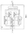
- Fig. 1 is a block diagram of an ADSL unit.
- the ADSL unit 100 employs high speed signal processing electronics 111 that includes, for example, digital signal processing (DSP) circuitry.
- Signal processing electronics 111 eliminate stray electronic noise induced on the two-wire loop 120 and, along with transmit circuitry 112 and receive circuitry 113, are used to send and receive modulated data.
- signal processing circuitry 111 may implement error correcting algorithms, such as the Reed-Solomon algorithm, to further reduce data errors that arise during transmission.
- the signal processing, transmit, and receive functions may be provided by, for example, a Motorola CopperGold chip set or a GlobeSpan Technologies STAR or SLADE chip set.
- Control circuitry 117 is provided to control operation of the ADSL unit 100, to control power usage by ADSL unit circuitry, and for storage of ADSL unit parameters.
- an ADSL unit 100 is located at each end of a wire loop 120.
- an ADSL unit 100 located at the subscriber premises 240 is referred to as a customer premises equipment (CPE) ADSL unit 242.
- a second ADSL unit 100, typically located at a telephone company central office 230, is known as the central office terminal (COT) unit 232.
- the CPE unit and the COT unit are connected by a two-wire loop 220 of up to 18,000 feet.
- Central office and customer premises equipment connects to the ADSL unit through a data interface 116 ( Fig: 1 ).
- the data interface of the COT unit 232 is connected to central office data switching equipment 234.
- the data interface of the CPE unit 242 is connected to customer premise equipment such as a personal computer 244.
- a frame is an arrangement of bits including both user data and signaling information required by the ADSL units. When there is nothing to transmit between ADSL units, the user data portion of the frame may be filled with idle packets.
- a low bit rate signaling channel over which handshaking information can be exchanged between ADSL units. This signaling channel may be used, for example, to test the wire loop transmission path and to send ADSL device status information.
- Circuitry within each ADSL unit 232 and 242 is used to remove noise, to perform error correction, to multiplex data, and to transmit and receive data. This is done without interfering with POTS audio and signaling transmissions over the two-wire loop 220, which uses spectrum below 4 kilohertz (kHz). Modulated data from the ADSL units 232 and 242 is transmitted using spectrum above 4 kHz, typically using a range of frequencies of 40 kHz and greater.
- Signal filters 233 and 243 are used to join signals being transmitted from one location, for example, the central office 230, and to separate signals when they are received at the distant location, for example, the customer premises 240.
- a splitter 233 is used to combine outgoing signals from the POTS switching equipment 231 and the COT ADSL unit 232 for transmission on the loop 220.
- the splitter 233 also provides signals received on the two-wire loop 220 to both the POTS switching equipment 231 and to the COT ADSL unit 232.
- Signals to be sent to the POTS switching equipment 231 are filtered by the splitter 233 so as to remove frequencies above voiceband.
- the resulting filtered signal may be handled by the POTS switch 231 as if it had originated on a traditional analog POTS connection.
- the signal from the splitter 233 to the COT ADSL unit 232 may contain the full frequency spectrum as it arrives over the wire loop 220 or may be filtered to remove voice band frequencies.
- a splitter 243 which may serve as a telephone company network interface (NI) device, is used to combine outgoing signals from customer premises POTS-compatible equipment 241 and the CPE ADSL unit 242 for transmission on the loop 220.
- the splitter 243 is also used to direct signals received on the two-wire loop 220 to both customer premises POTS equipment 241, such as an analog telephone or a FAX machine, and to the CPE ADSL unit 242.
- NI telephone company network interface
- Signals to be sent to the customer premises POTS equipment 241 are filtered to remove frequencies above voice band.
- the resulting filtered signal may be handled by the customer premises POTS equipment 241 as if it had originated on a traditional analog POTS connection.
- the signal from the splitter 243 to the CPE ADSL unit 242 may contain the full frequency spectrum as it arrives over the wire loop 220 or it may be filtered to remove voiceband frequencies.
- the CPE ADSL unit 242 may be incorporated in, for example, an ADSL modem connected to a personal computer 244 that is programmed to send and receive over the ADSL connection.
- Circuitry to handle POTS and ADSL data functions may be combined within a single physical device handling signal splitting and filtering, POTS call processing and modulated data processing, transmitting, and receiving. Alternatively, these functions may be achieved using a number of physically separate devices.
- signals Prior to initiating transport of modulated data over the loop 220, signals are exchanged over the loop 220 between the COT unit 232 and the CPE unit 242 to adapt the ADSL units to the electronic characteristics of the particular wire loop 220. For example, loop loss characteristics, which are a function of loop length, wire gauge, wire composition, and other factors, are exchanged. This exchange of information is often referred to as handshaking. Once handshaking is completed, transmission of user data may begin.
- the ADSL units 232 and 242 may enter low power mode when user data transmission is complete. Either unit may initiate the low power mode. If, for example, the CPE unit 242 initiates low power mode, it does so by sending a shut-down signal to the COT unit 232. This shut-down signal may be conveyed in the ADSL low bit rate signaling channel; alternatively, an out-of-band signal on the loop may be used, for example, a 16 kHz AC signal. Still another alternative is for the CPE unit to stop sending ADSL framing information (such as would happen if the CPE unit were powered down).
- the COT unit 232 Upon receipt of the shut-down signal, the COT unit 232 optionally stores in memory 117 characteristics of the loop 220 that were determined by CPE to COT handshaking. Likewise, upon sending the shut-down signal, the CPE unit 242 may also optionally store the loop characteristics that it obtained through CPE to COT handshaking. Storing loop characteristics enables rapid resumption of user data transmission when the units are returned to full power mode. Each unit 232 and 242 may then enter low-power mode by shutting off the now unnecessary sections of signal processing 111, transmitting 112, and receiving 113 circuitry. The loop 220 will then be in an inactive state. Circuitry 115 to detect the resume signal must remain capable of signal detection during low power operation. If the COT unit 232 were to initiate low power mode, signals would be exchanged with the CPE unit 242 in a like fashion.
- both CPE 242 and COT 232 units may be capable of reduced power operation.
- only the COT 232 unit may reduce its power consumption, or only the CPE unit 242 may reduce its power consumption. If only the COT unit 232 is to reduce its power consumption, the COT unit 232 will not require resume signal generation 114 circuitry, nor will the CPE unit 242 require resume signal detection circuitry 115. Similarly, if only the CPE unit 242 is to reduce power consumption, the CPE unit 242 will not require resume signal generation 114 circuitry nor will the COT unit 232 require resume signal detection circuitry.
- the particular circuit components that can be placed in a low power mode may vary among differing brands, models, and versions of ADSL units.
- a resume signal is sent to the unit.
- a COT ADSL unit resumes full power operation upon receipt of a 16 kHz AC signal that is sent over the wire loop by a CPE ADSL unit.
- This resume signal may be detected by the COT unit using a 16 kHz AC signal detector 115 that employs conventional frequency detection techniques. This detector 115 remains operative when the unit 232 is in low-power mode. If the CPE unit 242 is capable of reduced power operation, a resume signal sent from the COT unit 232 to the CPE unit 242 would be similarly received at the customer premises and detected by the CPE unit 242.
- the receiving ADSL unit Upon receipt of the resume signal, the receiving ADSL unit returns the signal processing 111, transmitting 112, and receiving 113 circuitry to full power mode. If loop transmission characteristics had been stored, these parameters are retrieved from memory 117 and used to enable data transmission to resume quickly by reducing the time needed to determine loop transmission characteristics. After resumption of full power mode, additional handshaking between ADSL units 232 and 242 may occur. Upon reaching a fully operational state, transmission of user data may resume.
- one exemplary application of the invention is to reduce power requirements needed to maintain a link between a personal computer (PC) 244 and a remote data source 250.
- the remote data source 250 may be, for example, an Internet service provider (ISP) or an online service provider (OSP).
- ISP Internet service provider
- OSP online service provider
- a CPE ADSL unit 242 is connected by a digital interface 247 to a personal computer 244 programmed to send and receive data over the ADSL unit 242.
- the CPE ADSL unit 242 may be incorporated in an ADSL modem that is installed in, or connected to, the PC 244.
- the CPE ADSL unit 242 is connected by a wire loop 220 to a COT ADSL unit 232 at a central office 230 at which a link to the remote data source 250 exists.
- the wire loop 220 is initially inactive, thus preventing information flow between the CPE 242 and COT 232 ADSL units.
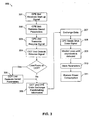
- a start-up signal is sent to the CPE ADSL unit (step 301).
- the start-up signal is, for example, a command sent over the digital interface 247 from a device driver or other program module running in the PC 244 or may be represented by power to the CPE ADSL unit being turned on.
- the CPE ADSL unit may restore saved loop characteristic parameters (step 302).
- the CPE ADSL unit transmits a 16 kHz resume signal on the loop (step 303)
- the resume signal is subsequently detected by loop monitoring circuitry in the COT unit (step 304).
- the COT unit If the COT unit is in a low power state, it will return to full power operation upon detection of the resume signal from the CPE unit, this may include restoring loop characteristic parameters (step 305). If the COT unit was not in a low power state, the resume signal may be ignored by the COT unit.
- CPE and COT ADSL units may then exchange handshaking information to establish reliable data communication between the units (step 306). Handshaking information may be required where, for example, loop characteristics have changed due, for example, to temperature-dependent changes in loop resistance. Handshaking information may also be exchanged for other device initialization purposes.
- the personal computer 244 may use the data path between ADSL units to communicate with a remote data source by sending information over a digital interface 247 to the CPE ADSL unit 242.
- This digital interface may be an industry standard computer interface such as a small computer systems interface (SCSI), an Ethernet interface, or a peripheral component interconnect (PCI) interface, or other industry standard or vendor proprietary interfaces allowing two-way data exchange.
- SCSI small computer systems interface
- Ethernet Ethernet
- PCI peripheral component interconnect
- Information from the PC to the CPE unit may include both user data and signaling information to control CPE ADSL unit operation or, by relaying such signaling over an ADSL to ADSL unit signaling channel, to control COT ADSL unit operation.
- User data provided to the CPE unit by the PC is transmitted to the COT unit over the established CPE to COT data transmission path.
- Data received at the COT unit may be converted to a data signal format compatible with standard telephone company switching equipment, for example, a 1.544 million bits per second (Mbps) T1 data signal, or to asynchronous transfer mode (ATM) cells over an optical carrier level 3 (OC-3) synchronous optical network (SONET) interface.
- the received data now in a central office equipment compatible format, may be provided over a standard telephony interface 236 to telephone company high speed data switching equipment 234, such as a digital cross connect switch or multiplexing equipment to a second interface 251 that connects to a remote data source 250.
- the data may flow from the COT ADSL unit 232 directly to the remote data source 250 without handling by intermediary switching equipment 234. Two way data transfers between the remote data source 250 and the PC 244 may then take place over the resulting path from PC 244 to CPE unit 242 to COT unit 232 to switching equipment 234 to remote data resource 250.
- the COT unit may be returned to low power mode by sending a shut-down signal from the CPE unit to the COT unit (step 308).
- the shut-down signal may be an expressly transmitted signal or may be inferred.
- the shut down signal may be expressly sent as a series of signaling bits transmitted between the CPE and COT ADSL units.
- a shut-down signal may be inferred from the loss of transmitted framing information between the CPE unit and the COT unit.
- the shut-down signal is subsequently detected by monitoring circuitry in the COT ADSL unit (step 309).
- the COT unit may save loop characteristics (step 310) and enter low power mode by reducing power to now unnecessary circuitry (step 311).
- the described procedure 300 may be repeated to resume data transmission. Essentially the same sequence may occur to reduce power at a CPE ADSL unit 242.
- a CPE ADSL unit may enter a low power mode when, for example, a preset or programmed period of time passes without any user activity on the data path or an appropriate signal is sent from the COT ADSL unit.
Landscapes
- Engineering & Computer Science (AREA)
- Signal Processing (AREA)
- Computer Networks & Wireless Communication (AREA)
- Telephonic Communication Services (AREA)
- Interface Circuits In Exchanges (AREA)
- Transmitters (AREA)
- Devices For Supply Of Signal Current (AREA)
- Cable Transmission Systems, Equalization Of Radio And Reduction Of Echo (AREA)
- Telephone Function (AREA)
- Near-Field Transmission Systems (AREA)
- Facsimiles In General (AREA)
- Digital Transmission Methods That Use Modulated Carrier Waves (AREA)
Claims (24)
- Verfahren zum Energiesparen in einer Endgeräteeinheit (100) für einen asymmetrischen digitalen Teilnehmer-Anschluss (ADSL), einen symmetrischen digitalen Teilnehmer-Anschluss (SDSL) oder einen ratenadaptiven digitalen Teilnehmer-Anschluss (RADSL) mit einem Sender (112) und einem Empfänger (113) für modulierte Datenkommunikation über eine Kommunikationsschleife (120), die mit Voiceband-Telefonausrüstung (231, 241) gemeinsam benutzt wird, wobei Voiceband-Dienstleistungen die Schleife mit modulierter Datenübertragung gemeinsam benutzen, gekennzeichnet durch:Überwachen der Schleife (120), um ein ausdrücklich übertragenes Abschaltsignal zu erfassen, das auf eine Abschalt-Bedingung hinweist;Verringern des Energieverbrauchs der Signalverarbeitungsschaltung (111), der Übertragungsschaltung (112) zum Senden von modulierten Daten und der Empfangsschaltung (113) zum Empfangen von modulierten Daten in der Endgeräteeinheit auf eine Erfassung einer Abschalt-Bedingung hin;Überwachen der Schleife mit einer Überwachungsschaltung (115), um ein Wiederaufnahme-Signal außerhalb des Voiceband-Frequenzbereichs auf der Schleife (120) in Form eines AC-Signals, das größer ist als 4 kHz, zu erfassen; undWiederherstellen der Energie an die Signalverarbeitungsschaltung (111), die Übertragungsschaltung (112) und die Empfangsschaltung (113), wenn das Wiederaufnahme-Signal erfasst ist.
- Verfahren nach Anspruch 1, wobei modulierte Daten einen Bitrahmen umfassen, der Signalisierungsbits und Datenbits einschließt, und wobei das Überwachen der Schleife, um ein Abschalt-Signal zu erfassen, das Überwachen von Signalisierungsbits in dem Bitrahmen umfasst.
- Verfahren nach Anspruch 1, wobei das Wiederaufnahme-Signal ein 16 kHz-AC-Signal umfasst.
- Verfahren nach Anspruch 1, weiter umfassend:Speichern von schleifenspezifischen Parametern in einem Speicher (117) auf den Empfang des Abschaltsignals hin; undWiederherstellen der schleifenspezifischen Parameter aus dem Speicher (117) auf ein Wiederherstellen der Energie an die Empfangsschaltung (113) hin.
- Verfahren nach Anspruch 4, weiter umfassend ein Durchführen eines Handshaking, um Schleifeneigenschaften zu bestimmen.
- Sende- und Empfangseinheit für modulierte Daten, umfassend
eine Verbindungseinrichtung, welche die Einheit funktionsfähig mit einer Kommunikationsschleife (120) koppelt, die mit Voiceband-Telefonausrüstung (231, 241) gemeinsam benutzt wird;
eine erste Schaltungsanordnung (111, 112, 113), die mit der Verbindungseinrichtung gekoppelt ist, um ein moduliertes Datensignal in einem Frequenzbereich oberhalb von Voiceband zu senden und zu empfangen;
gekennzeichnet durch:eine Speicherschaltungsanordnurig (117), die funktionsfähig mit der ersten Schaltungsanordnung (111, 112, 113) gekoppelt ist, um schleifenspezifische Parameter während eines Niederenergie-Zustands zu speichern, und um schleifenspezifische Parameter während einer Einschaltsequenz wieder herzustellen; undeine zweite Schaltungsanordnung (115), die mit der Verbindungseinrichtung gekoppelt ist, um ein Wiederaufnahme-Signal in dem Frequenzbereich oberhalb von Voiceband zu erfassen und dann die Einschaltsequenz für die erste Schaltungsanordnung einzuleiten. - Sende- und Empfangseinheit für modulierte Daten nach Anspruch 6, wobei die Verbindungseinrichtung eine Verbindungseinrichtung mit zwei Leitungen umfasst.
- Sende- und Empfangseinheit für modulierte Daten nach Anspruch 6, wobei die erste Schaltungsanordnung Asymmetrie Digital Subscriber Line-Datenübertragungsschaltungen umfasst.
- Sende- und Empfangseinheit für modulierte Daten nach Anspruch 6, wobei die zweite Schaltungsanordnung eine 16 kHz-Frequenz-Erfassungsschaltungsanordnung umfasst.
- Sende- und Empfangseinheit für modulierte Daten nach Anspruch 6, wobei die Kommunikationsschleife (120) eine Drahtlos-Kommunikationsschleife umfasst.
- Sende- und Empfangseinheit für modulierte Daten nach Anspruch 6, wobei das Wiederaufnahme-Signal ein AC-Signal mit mehr als 4 kHz umfasst.
- Sende- und Empfangseinheit für modulierte Daten nach Anspruch 6, wobei das Wiederaufnahme-Signal eine Übertragung eines AC-Signals bei einer ersten Frequenz, gefolgt von einer Übertragung eines AC-Signals bei einer zweiten Frequenz umfasst.
- Sende- und Empfangseinheit für modulierte Daten nach Anspruch 6, weiter umfassend;
eine Steuersignalschnittstelle zum Empfangen eines Start-Signals; und
eine dritte Schaltungsanordnung (114), die mit der Verbindungseinrichtung gekoppelt ist, um ein Wiederaufnahmesignal an die Schleife (120) auf den Empfang eines Start-Signals an der Steuersignalschnittstelle hin zu senden. - Sende- und Empfangseinheit für modulierte Daten nach Anspruch 6, wobei die Einheit eingerichtet ist, ein Handshaking durchzufiihren, um schleifenspezifsche Parameter zu bestimmen, die mit der Schleife (120) verknüpft sind.
- Sende- und Empfangseinheit für modulierte Daten, umfassend
eine Verbindungseinrichtung, welche die Einheit funktionsfähig mit einer Kommunikationsschleife (120) koppelt, die mit Voiceband-Telefonausrüstung (231, 241) gemeinsam benutzt wird;
eine erste Schaltungsanordnung (111, 112, 113), die mit der Verbindungseinrichtung gekoppelt ist, um ein moduliertes Datensignal auf Frequenzen oberhalb von Voiceband zu senden und zu empfangen;
gekennzeichnet durch:eine Steuersignalschnittstelle zum Empfangen eines Start-Signals;eine Speicherschaltungsanordnung (117), die funktionsfähig mit der ersten Schaltungsanordnung (111, 112, 113) gekoppelt ist, zum Speichern von schleifenspezifischen Parametern während eines Niedezenergie-Zustarids und zum Wiederherstellen von schleifenspezifischen Parametern auf den Empfang des Startsignals an der Steuersignalschnittstelle hin; undeine zweite Schaltungsanordnung (114), die mit der Verbindungseinrichtung gekoppelt ist, zum Übertragen eines Wiederaufnahme-Signals, um eine Einschaltsequenz an der Schleife einzuleiten, auf einen Empfang eines Startsignals an der Steuersignalschnittstelle hin. - Sende- und Empfangseinheit für modulierte Daten nach Anspruch 15, wobei die Kommunikationsschleife (120) eine Kommunikationsschleife mit zwei Leitungen umfasst.
- Sende- und Empfangseinheit für modulierte Daten nach Anspruch 15, wobei die Kommunikationsschleife (120) eine Drahtlos-Kommunikationsschleife umfasst.
- Sende- und Empfangseinheit für modulierte Daten nach Anspruch 15, wobei die Steuersignalschnittstelle eine Datenschnittstelle umfasst.
- Sende- und Empfangseinheit für modulierte Daten nach Anspruch 18, wobei die Datenschnittstelle eine peripheral component interconnect (PCI)-Schnittstelle umfasst.
- Sende- und Empfangseinheit für modulierte Daten nach Anspruch 18, wobei der Empfang des Start-Signals an der Steuersigrialschnittstelle einen Empfang von Daten an der Steuersignalschnittstelle umfasst.
- Sende- und Empfangseinheit für modulierte Daten nach Anspruch 15, wobei die Steuersignalschnittstelle einen Austausch von einem Startsignal und von Daten zwischen der Sende- und Empfangseinheit für modulierte Daten und einem Kunden-Endgerät ermöglicht.
- Sende- und Empfangseinheit für modulierte Daten nach Anspruch 15, wobei die Einheit eingerichtet ist, ein Handshaking durchzufiihren, um schleifenspezifische Parameter zu bestimmen, die mit der Schleife (120) verknüpft sind.
- Sende- und Empfangseinheit für modulierte Daten nach Anspruch 6, umfassend:eine Signalverarbeitungsschaltung (111);eine Übertragungsschaltung (112) zum Senden von modulierten Daten über die Kommunikationsschleife;eine Empfangsschaltung (113), die mit der Verbindungseinrichtung gekoppelt ist, zum Empfangen von modulierten Daten über die Kommunikationsschleife (120);eine Energie-Steuerungsschaltungsanordnung (117), die mit der Signalverarbeitungsschaltung (111), der Übertragungsschaltung (112) und der Empfangsschaltung (113) gekoppelt ist;eine Überwachungsschaltung, die eingerichtet ist, ein Abschaltsignal auf der Schleife zu erfassen,wobei die Einheit eingerichtet ist, die Signalverarbeitungsschaltung (111), die Übertragungsschaltung (112) und die Empfangsschaltung (113) auf den Empfang eines Abschaltsignals hin abzuschalten; undeine Überwachungsschaltung (115), die eingerichtet ist, ein Wiederaufnahme-Signal zu erfassen, das sich außerhalb des Voiceband-Frequenzbereichs befindet,wobei die Einheit (100) eingerichtet ist, eine Einschalt-Sequenz für die Signalverarbeitungsschaltung (111), die Übertragungsschaltung (112) und die Empfangsschaltung (113) auf die Erfassung des Wiederaufnahme-Signals hin einzuleiten.
- Sende- und Empfangseinheit für modulierte Daten nach Anspruch 23, wobei die Überwachungsschaltungsanordnung (115) eine Schaltungsanordnung umfasst, um ein Wechselstrom-Signal bei einer Frequenz oberhalb von Voiceband zu erfassen.
Priority Applications (2)
| Application Number | Priority Date | Filing Date | Title |
|---|---|---|---|
| EP10178560.8A EP2267939A3 (de) | 1997-07-30 | 1998-07-30 | Stromkonservierung für POTS und modulierte Datenübertragung |
| EP07075218A EP1798992A1 (de) | 1997-07-30 | 1998-07-30 | Energieeinsparung für Pots und modulierte Datenübertragung |
Applications Claiming Priority (3)
| Application Number | Priority Date | Filing Date | Title |
|---|---|---|---|
| US08/903,504 US5956323A (en) | 1997-07-30 | 1997-07-30 | Power conservation for pots and modulated data transmission |
| US903504 | 1997-07-30 | ||
| PCT/US1998/015751 WO1999007162A1 (en) | 1997-07-30 | 1998-07-30 | Power conservation for pots and modulated data transmission |
Related Child Applications (2)
| Application Number | Title | Priority Date | Filing Date |
|---|---|---|---|
| EP07075218A Division EP1798992A1 (de) | 1997-07-30 | 1998-07-30 | Energieeinsparung für Pots und modulierte Datenübertragung |
| EP07075218.3 Division-Into | 2007-03-21 |
Publications (4)
| Publication Number | Publication Date |
|---|---|
| EP1005755A1 EP1005755A1 (de) | 2000-06-07 |
| EP1005755A4 EP1005755A4 (de) | 2005-07-06 |
| EP1005755B1 EP1005755B1 (de) | 2007-03-28 |
| EP1005755B2 true EP1005755B2 (de) | 2010-10-20 |
Family
ID=25417614
Family Applications (3)
| Application Number | Title | Priority Date | Filing Date |
|---|---|---|---|
| EP10178560.8A Withdrawn EP2267939A3 (de) | 1997-07-30 | 1998-07-30 | Stromkonservierung für POTS und modulierte Datenübertragung |
| EP98938102A Expired - Lifetime EP1005755B2 (de) | 1997-07-30 | 1998-07-30 | Energieeinsparung für pots und modulierte datenübertragung |
| EP07075218A Withdrawn EP1798992A1 (de) | 1997-07-30 | 1998-07-30 | Energieeinsparung für Pots und modulierte Datenübertragung |
Family Applications Before (1)
| Application Number | Title | Priority Date | Filing Date |
|---|---|---|---|
| EP10178560.8A Withdrawn EP2267939A3 (de) | 1997-07-30 | 1998-07-30 | Stromkonservierung für POTS und modulierte Datenübertragung |
Family Applications After (1)
| Application Number | Title | Priority Date | Filing Date |
|---|---|---|---|
| EP07075218A Withdrawn EP1798992A1 (de) | 1997-07-30 | 1998-07-30 | Energieeinsparung für Pots und modulierte Datenübertragung |
Country Status (9)
| Country | Link |
|---|---|
| US (1) | US5956323A (de) |
| EP (3) | EP2267939A3 (de) |
| JP (4) | JP2001512937A (de) |
| CN (1) | CN1119903C (de) |
| AT (1) | ATE358394T1 (de) |
| AU (1) | AU745929B2 (de) |
| DE (1) | DE69837436T3 (de) |
| NO (1) | NO20000402L (de) |
| WO (1) | WO1999007162A1 (de) |
Families Citing this family (39)
| Publication number | Priority date | Publication date | Assignee | Title |
|---|---|---|---|---|
| US6470046B1 (en) * | 1997-02-26 | 2002-10-22 | Paradyne Corporation | Apparatus and method for a combined DSL and voice system |
| US20040160906A1 (en) | 2002-06-21 | 2004-08-19 | Aware, Inc. | Multicarrier transmission system with low power sleep mode and rapid-on capability |
| US6480510B1 (en) | 1998-07-28 | 2002-11-12 | Serconet Ltd. | Local area network of serial intelligent cells |
| EP0991223A1 (de) * | 1998-09-30 | 2000-04-05 | Alcatel | Verfahren und Einrichtung für einen schnellen Übergang eines niedrigen Leistungszustandes zu einem hohen Leistungszustand in ein Kommunikationssystem |
| US6480603B1 (en) * | 1998-11-06 | 2002-11-12 | Nortel Networks Limited | Device which reduces central office battery current during modem connections |
| US7075903B1 (en) * | 1999-04-14 | 2006-07-11 | Adc Telecommunications, Inc. | Reduced power consumption in a communication device |
| US6956826B1 (en) | 1999-07-07 | 2005-10-18 | Serconet Ltd. | Local area network for distributing data communication, sensing and control signals |
| US6690677B1 (en) | 1999-07-20 | 2004-02-10 | Serconet Ltd. | Network for telephony and data communication |
| US6640101B1 (en) | 1999-08-06 | 2003-10-28 | Bellsouth Intellectual Property Corporation | Remote transmission testing and monitoring to a cell site in a cellular communications network |
| US6493355B1 (en) * | 1999-09-27 | 2002-12-10 | Conexant Systems, Inc. | Method and apparatus for the flexible use of speech coding in a data communication network |
| US7200156B2 (en) * | 1999-12-21 | 2007-04-03 | Skarpness Mark L | Modular broadband adapter system |
| US6829292B1 (en) | 2000-01-03 | 2004-12-07 | Symmetricom, Inc. | Increasing gain with isolating upstream and downstream filters and amplifiers |
| US6549616B1 (en) | 2000-03-20 | 2003-04-15 | Serconet Ltd. | Telephone outlet for implementing a local area network over telephone lines and a local area network using such outlets |
| US6507606B2 (en) | 2000-03-29 | 2003-01-14 | Symmetrican, Inc. | Asymmetric digital subscriber line methods suitable for long subscriber loops |
| IL135744A (en) | 2000-04-18 | 2008-08-07 | Mosaid Technologies Inc | Telephone communication system through a single line |
| US6842459B1 (en) | 2000-04-19 | 2005-01-11 | Serconet Ltd. | Network combining wired and non-wired segments |
| US6842426B2 (en) | 2000-04-21 | 2005-01-11 | Symmetricom, Inc. | Fault detection for subscriber loop repeaters |
| US7142619B2 (en) * | 2000-04-26 | 2006-11-28 | Symmetricom, Inc. | Long subscriber loops using automatic gain control mid-span extender unit |
| US20020061058A1 (en) * | 2000-07-25 | 2002-05-23 | Symmetricom, Inc. | Subscriber loop repeater loopback for fault isolation |
| DE10059014B4 (de) * | 2000-11-28 | 2004-03-25 | Winbond Electronics Corp | Vorrichtung und Verfahren zur Fernaktivierung eines im Wartezustand befindlichen Computers |
| WO2002065746A1 (en) * | 2001-02-13 | 2002-08-22 | Infineon Technologies Ag | System and method for establishing an xdsl data transfer link |
| IL144158A (en) | 2001-07-05 | 2011-06-30 | Mosaid Technologies Inc | Socket for connecting an analog telephone to a digital communications network that carries digital voice signals |
| US20030068024A1 (en) * | 2001-10-05 | 2003-04-10 | Jones William W. | Communication system activation |
| US20030210708A1 (en) * | 2002-05-07 | 2003-11-13 | Belotserkovsky Maxim B. | Digital telephone system and protocol for joint voice and data exchange via pots line |
| IL152824A (en) | 2002-11-13 | 2012-05-31 | Mosaid Technologies Inc | A socket that can be connected to and the network that uses it |
| IL154234A (en) | 2003-01-30 | 2010-12-30 | Mosaid Technologies Inc | Method and system for providing dc power on local telephone lines |
| IL154921A (en) | 2003-03-13 | 2011-02-28 | Mosaid Technologies Inc | A telephone system that includes many separate sources and accessories for it |
| IL157787A (en) | 2003-09-07 | 2010-12-30 | Mosaid Technologies Inc | Modular outlet for data communications network |
| IL159838A0 (en) | 2004-01-13 | 2004-06-20 | Yehuda Binder | Information device |
| IL160417A (en) | 2004-02-16 | 2011-04-28 | Mosaid Technologies Inc | Unit added to the outlet |
| CN100502291C (zh) * | 2005-08-22 | 2009-06-17 | 华为技术有限公司 | 一种通讯装置和节省通讯装置静态功耗的方法 |
| CN101207968B (zh) * | 2006-12-22 | 2011-11-09 | 鸿富锦精密工业(深圳)有限公司 | 电路板 |
| EP2127332A4 (de) * | 2007-01-16 | 2014-01-29 | Ikanos Communications Inc | Verfahren und vorrichtung für ein dsl-leitungskarten-leistungsmanagement |
| DE102011075996B3 (de) * | 2011-05-17 | 2012-10-11 | Siemens Aktiengesellschaft | Verfahren zum Betrieb einer Automatisierungseinrichtung mit einem Kommunikationsmodul |
| US8812670B2 (en) | 2011-10-11 | 2014-08-19 | Telefonaktiebolaget L M Ericsson (Publ) | Architecture for virtualized home IP service delivery |
| EP2648363B1 (de) | 2012-04-05 | 2017-10-11 | Lantiq Deutschland GmbH | Verfahren zur Regelung eines Leistungsstatus einer Netzwerkeinheit |
| US9025439B2 (en) | 2012-06-26 | 2015-05-05 | Telefonaktiebolaget L M Ericsson (Publ) | Method and system to enable re-routing for home networks upon connectivity failure |
| US9203694B2 (en) | 2013-03-15 | 2015-12-01 | Telefonaktiebolaget L M Ericsson (Publ) | Network assisted UPnP remote access |
| CN105391874B (zh) * | 2014-09-09 | 2018-05-18 | 上海核工程研究设计院 | 符合国内核电厂使用需求的检修电话系统 |
Family Cites Families (19)
| Publication number | Priority date | Publication date | Assignee | Title |
|---|---|---|---|---|
| US4484028A (en) * | 1982-11-01 | 1984-11-20 | Motorola, Inc. | Digital loop transceiver having a power up/down circuit |
| JPS62133893A (ja) * | 1985-12-06 | 1987-06-17 | Kokusai Syst Kk | シグナリングパルス伝送装置 |
| DE3545572A1 (de) * | 1985-12-21 | 1987-06-25 | Philips Patentverwaltung | Verfahren und einrichtung zum unhoerbaren kennungsaustausch zwischen einem funkstationspaar |
| JPH0789627B2 (ja) * | 1986-09-04 | 1995-09-27 | 株式会社東芝 | 回線接続装置のパラメ−タ保持方式 |
| JPH01204549A (ja) * | 1988-02-10 | 1989-08-17 | Mitsubishi Electric Corp | 変復調装置 |
| JPH01220949A (ja) * | 1988-02-29 | 1989-09-04 | Nec Corp | 帯域外シグナリング信号の検出回路 |
| US4979208A (en) * | 1988-06-29 | 1990-12-18 | Mars Incorporated | Method and apparatus for electronic payphone open switch interval management |
| JPH02246562A (ja) * | 1989-03-20 | 1990-10-02 | Fujitsu Ltd | 単一周波数信号受信回路 |
| JP2968291B2 (ja) * | 1989-12-05 | 1999-10-25 | 富士通株式会社 | 2周波混合信号の検出装置 |
| JPH04115767A (ja) * | 1990-09-05 | 1992-04-16 | Matsushita Electric Ind Co Ltd | 回線端末装置 |
| US5195125A (en) * | 1990-09-17 | 1993-03-16 | Raychem Corporation | Gel filled RJ11 connector |
| JP2905616B2 (ja) * | 1991-05-20 | 1999-06-14 | シャープ株式会社 | 通信端末装置 |
| US5491721A (en) * | 1994-02-23 | 1996-02-13 | Motorola, Inc. | Modem powering method and apparatus |
| US5590396A (en) * | 1994-04-20 | 1996-12-31 | Ericsson Inc. | Method and apparatus for a deep-sleep mode in a digital cellular communication system |
| US5631952A (en) * | 1994-10-18 | 1997-05-20 | Motorola, Inc. | Apparatus and method for modem wake-up with autobaud function |
| US5799064A (en) * | 1995-08-31 | 1998-08-25 | Motorola, Inc. | Apparatus and method for interfacing between a communications channel and a processor for data transmission and reception |
| US5756280A (en) * | 1995-10-03 | 1998-05-26 | International Business Machines Corporation | Multimedia distribution network including video switch |
| US5757803A (en) | 1995-11-27 | 1998-05-26 | Analog Devices, Inc. | Pots splitter assembly with improved transhybrid loss for digital subscriber loop transmission |
| US5742527A (en) * | 1996-03-15 | 1998-04-21 | Motorola, Inc. | Flexible asymmetrical digital subscriber line (ADSL) receiver, central office using same, and method therefor |
-
1997
- 1997-07-30 US US08/903,504 patent/US5956323A/en not_active Expired - Lifetime
-
1998
- 1998-07-30 EP EP10178560.8A patent/EP2267939A3/de not_active Withdrawn
- 1998-07-30 AU AU86703/98A patent/AU745929B2/en not_active Expired
- 1998-07-30 CN CN98807744A patent/CN1119903C/zh not_active Expired - Lifetime
- 1998-07-30 DE DE69837436T patent/DE69837436T3/de not_active Expired - Lifetime
- 1998-07-30 EP EP98938102A patent/EP1005755B2/de not_active Expired - Lifetime
- 1998-07-30 WO PCT/US1998/015751 patent/WO1999007162A1/en active IP Right Grant
- 1998-07-30 JP JP2000505753A patent/JP2001512937A/ja active Pending
- 1998-07-30 AT AT98938102T patent/ATE358394T1/de not_active IP Right Cessation
- 1998-07-30 EP EP07075218A patent/EP1798992A1/de not_active Withdrawn
-
2000
- 2000-01-26 NO NO20000402A patent/NO20000402L/no unknown
-
2008
- 2008-03-26 JP JP2008080220A patent/JP2008245287A/ja not_active Withdrawn
-
2011
- 2011-08-05 JP JP2011171517A patent/JP2011217423A/ja not_active Withdrawn
-
2014
- 2014-08-28 JP JP2014174467A patent/JP5731049B2/ja not_active Expired - Lifetime
Also Published As
| Publication number | Publication date |
|---|---|
| JP2001512937A (ja) | 2001-08-28 |
| JP5731049B2 (ja) | 2015-06-10 |
| CN1276948A (zh) | 2000-12-13 |
| US5956323A (en) | 1999-09-21 |
| AU745929B2 (en) | 2002-04-11 |
| DE69837436T2 (de) | 2007-12-13 |
| EP1005755A1 (de) | 2000-06-07 |
| JP2008245287A (ja) | 2008-10-09 |
| ATE358394T1 (de) | 2007-04-15 |
| AU8670398A (en) | 1999-02-22 |
| JP2014225927A (ja) | 2014-12-04 |
| NO20000402L (no) | 2000-03-27 |
| CN1119903C (zh) | 2003-08-27 |
| EP2267939A2 (de) | 2010-12-29 |
| DE69837436D1 (de) | 2007-05-10 |
| EP1005755A4 (de) | 2005-07-06 |
| WO1999007162A8 (en) | 2000-06-08 |
| NO20000402D0 (no) | 2000-01-26 |
| EP2267939A3 (de) | 2013-10-30 |
| EP1798992A1 (de) | 2007-06-20 |
| WO1999007162A1 (en) | 1999-02-11 |
| JP2011217423A (ja) | 2011-10-27 |
| EP1005755B1 (de) | 2007-03-28 |
| DE69837436T3 (de) | 2011-05-12 |
Similar Documents
| Publication | Publication Date | Title |
|---|---|---|
| EP1005755B2 (de) | Energieeinsparung für pots und modulierte datenübertragung | |
| US6647117B1 (en) | Continuity of voice carried over DSL during power failure | |
| US7707446B2 (en) | System and method for minimized power consumption for frame and cell data transmission systems | |
| US6781981B1 (en) | Adding DSL services to a digital loop carrier system | |
| US20020167949A1 (en) | Apparatus and method for asynchronous transfer mode (ATM) adaptive time domain duplex (ATDD) communication | |
| EP1176792A1 (de) | Verfahren und Vorrichtung zur optimierte Leistungsversorgung in einem digitalen Übertragungssystem | |
| US8345859B2 (en) | Method and apparatus for DSL line card power management | |
| US6952399B1 (en) | Method and apparatus for synchronizing the coding and decoding of information in an integrated services hub | |
| WO2001017219A1 (en) | Enhanced line card and packetizing cpe for lifeline packet voice telephone | |
| US6880093B1 (en) | Low power communication device | |
| US6922415B1 (en) | Apparatus and method for a non-symmetrical half-duplex DSL modem | |
| JP2005323301A (ja) | Dslモデム装置及びdslモデム装置の制御方法 | |
| JP2014531809A (ja) | Xdsl伝送システムのための非規格モードを開始するための方法、およびその方法を使用したレジデンシャルゲートウェイ | |
| US20050025153A1 (en) | Apparatus and method for asynchronous transfer mode (atm) adaptive time domain duplex (atdd) communication | |
| US20050111534A1 (en) | Method and system for selecting an optimal asymmetric digital subscriber line mode | |
| CN1552152B (zh) | 发送数据流的方法和设备 | |
| KR20010094554A (ko) | 에이티엠 정합 에이디에스엘 모뎀 | |
| WO1998038813A2 (en) | Apparatus and method for a multipoint dsl modem | |
| KR20000044357A (ko) | 디지탈 가입자 선 전송장치의 원격감시방법 | |
| JP2003333205A (ja) | 加入者線にデジタル信号を重畳するモデムとその電話機のダイヤル方式変換 | |
| CA2382334A1 (en) | Enhanced line card and packetizing cpe for lifeline packet voice telephone | |
| JP2003333204A (ja) | 加入者線にデジタル信号を重畳するモデムとその電話機 |
Legal Events
| Date | Code | Title | Description |
|---|---|---|---|
| PUAI | Public reference made under article 153(3) epc to a published international application that has entered the european phase |
Free format text: ORIGINAL CODE: 0009012 |
|
| 17P | Request for examination filed |
Effective date: 20000125 |
|
| AK | Designated contracting states |
Kind code of ref document: A1 Designated state(s): AT BE CH DE FI FR GB IT LI NL SE |
|
| RIN1 | Information on inventor provided before grant (corrected) |
Inventor name: BOWIE, BRUCE, H. |
|
| A4 | Supplementary search report drawn up and despatched |
Effective date: 20050525 |
|
| RIC1 | Information provided on ipc code assigned before grant |
Ipc: 7H 04M 19/08 B Ipc: 7H 04L 12/12 B Ipc: 7H 04L 12/10 B Ipc: 7H 04M 11/06 B Ipc: 7H 04Q 1/00 A |
|
| RAP1 | Party data changed (applicant data changed or rights of an application transferred) |
Owner name: NOKIA HIGH SPEED ACCESS PRODUCTS, INC. |
|
| GRAP | Despatch of communication of intention to grant a patent |
Free format text: ORIGINAL CODE: EPIDOSNIGR1 |
|
| GRAS | Grant fee paid |
Free format text: ORIGINAL CODE: EPIDOSNIGR3 |
|
| GRAA | (expected) grant |
Free format text: ORIGINAL CODE: 0009210 |
|
| AK | Designated contracting states |
Kind code of ref document: B1 Designated state(s): AT BE CH DE FI FR GB IT LI NL SE |
|
| PG25 | Lapsed in a contracting state [announced via postgrant information from national office to epo] |
Ref country code: NL Free format text: LAPSE BECAUSE OF FAILURE TO SUBMIT A TRANSLATION OF THE DESCRIPTION OR TO PAY THE FEE WITHIN THE PRESCRIBED TIME-LIMIT Effective date: 20070328 Ref country code: LI Free format text: LAPSE BECAUSE OF FAILURE TO SUBMIT A TRANSLATION OF THE DESCRIPTION OR TO PAY THE FEE WITHIN THE PRESCRIBED TIME-LIMIT Effective date: 20070328 Ref country code: FI Free format text: LAPSE BECAUSE OF FAILURE TO SUBMIT A TRANSLATION OF THE DESCRIPTION OR TO PAY THE FEE WITHIN THE PRESCRIBED TIME-LIMIT Effective date: 20070328 Ref country code: CH Free format text: LAPSE BECAUSE OF FAILURE TO SUBMIT A TRANSLATION OF THE DESCRIPTION OR TO PAY THE FEE WITHIN THE PRESCRIBED TIME-LIMIT Effective date: 20070328 Ref country code: BE Free format text: LAPSE BECAUSE OF FAILURE TO SUBMIT A TRANSLATION OF THE DESCRIPTION OR TO PAY THE FEE WITHIN THE PRESCRIBED TIME-LIMIT Effective date: 20070328 Ref country code: AT Free format text: LAPSE BECAUSE OF FAILURE TO SUBMIT A TRANSLATION OF THE DESCRIPTION OR TO PAY THE FEE WITHIN THE PRESCRIBED TIME-LIMIT Effective date: 20070328 |
|
| REG | Reference to a national code |
Ref country code: GB Ref legal event code: FG4D |
|
| REG | Reference to a national code |
Ref country code: CH Ref legal event code: EP |
|
| REF | Corresponds to: |
Ref document number: 69837436 Country of ref document: DE Date of ref document: 20070510 Kind code of ref document: P |
|
| PG25 | Lapsed in a contracting state [announced via postgrant information from national office to epo] |
Ref country code: SE Free format text: LAPSE BECAUSE OF FAILURE TO SUBMIT A TRANSLATION OF THE DESCRIPTION OR TO PAY THE FEE WITHIN THE PRESCRIBED TIME-LIMIT Effective date: 20070628 |
|
| REG | Reference to a national code |
Ref country code: CH Ref legal event code: PL |
|
| NLV1 | Nl: lapsed or annulled due to failure to fulfill the requirements of art. 29p and 29m of the patents act | ||
| RAP2 | Party data changed (patent owner data changed or rights of a patent transferred) |
Owner name: WI-LAN INC. |
|
| PLBI | Opposition filed |
Free format text: ORIGINAL CODE: 0009260 |
|
| PLAX | Notice of opposition and request to file observation + time limit sent |
Free format text: ORIGINAL CODE: EPIDOSNOBS2 |
|
| 26 | Opposition filed |
Opponent name: INFINEON TECHNOLOGIES AG Effective date: 20071228 |
|
| REG | Reference to a national code |
Ref country code: GB Ref legal event code: 732E |
|
| PLAF | Information modified related to communication of a notice of opposition and request to file observations + time limit |
Free format text: ORIGINAL CODE: EPIDOSCOBS2 |
|
| PLBB | Reply of patent proprietor to notice(s) of opposition received |
Free format text: ORIGINAL CODE: EPIDOSNOBS3 |
|
| REG | Reference to a national code |
Ref country code: FR Ref legal event code: TP |
|
| PLBP | Opposition withdrawn |
Free format text: ORIGINAL CODE: 0009264 |
|
| PUAH | Patent maintained in amended form |
Free format text: ORIGINAL CODE: 0009272 |
|
| STAA | Information on the status of an ep patent application or granted ep patent |
Free format text: STATUS: PATENT MAINTAINED AS AMENDED |
|
| 27A | Patent maintained in amended form |
Effective date: 20101020 |
|
| AK | Designated contracting states |
Kind code of ref document: B2 Designated state(s): AT BE CH DE FI FR GB IT LI NL SE |
|
| REG | Reference to a national code |
Ref country code: DE Ref legal event code: R082 Ref document number: 69837436 Country of ref document: DE Representative=s name: MARKS & CLERK (LUXEMBOURG) LLP, LU |
|
| PGFP | Annual fee paid to national office [announced via postgrant information from national office to epo] |
Ref country code: DE Payment date: 20150722 Year of fee payment: 18 |
|
| PGFP | Annual fee paid to national office [announced via postgrant information from national office to epo] |
Ref country code: IT Payment date: 20150727 Year of fee payment: 18 |
|
| REG | Reference to a national code |
Ref country code: FR Ref legal event code: PLFP Year of fee payment: 19 |
|
| REG | Reference to a national code |
Ref country code: DE Ref legal event code: R119 Ref document number: 69837436 Country of ref document: DE |
|
| PG25 | Lapsed in a contracting state [announced via postgrant information from national office to epo] |
Ref country code: DE Free format text: LAPSE BECAUSE OF NON-PAYMENT OF DUE FEES Effective date: 20170201 |
|
| REG | Reference to a national code |
Ref country code: FR Ref legal event code: PLFP Year of fee payment: 20 |
|
| PGFP | Annual fee paid to national office [announced via postgrant information from national office to epo] |
Ref country code: FR Payment date: 20170613 Year of fee payment: 20 |
|
| PG25 | Lapsed in a contracting state [announced via postgrant information from national office to epo] |
Ref country code: IT Free format text: LAPSE BECAUSE OF NON-PAYMENT OF DUE FEES Effective date: 20160730 |
|
| PGFP | Annual fee paid to national office [announced via postgrant information from national office to epo] |
Ref country code: GB Payment date: 20170726 Year of fee payment: 20 |
|
| REG | Reference to a national code |
Ref country code: GB Ref legal event code: 732E Free format text: REGISTERED BETWEEN 20180104 AND 20180110 |
|
| REG | Reference to a national code |
Ref country code: FR Ref legal event code: TP Owner name: WI-LAN INC., CA Effective date: 20180418 |
|
| REG | Reference to a national code |
Ref country code: GB Ref legal event code: PE20 Expiry date: 20180729 |
|
| PG25 | Lapsed in a contracting state [announced via postgrant information from national office to epo] |
Ref country code: GB Free format text: LAPSE BECAUSE OF EXPIRATION OF PROTECTION Effective date: 20180729 |