EP1005146B1 - Filter für Gleichspannungswandler - Google Patents
Filter für Gleichspannungswandler Download PDFInfo
- Publication number
- EP1005146B1 EP1005146B1 EP99117841A EP99117841A EP1005146B1 EP 1005146 B1 EP1005146 B1 EP 1005146B1 EP 99117841 A EP99117841 A EP 99117841A EP 99117841 A EP99117841 A EP 99117841A EP 1005146 B1 EP1005146 B1 EP 1005146B1
- Authority
- EP
- European Patent Office
- Prior art keywords
- filter
- voltage
- auxiliary
- source
- converter
- Prior art date
- Legal status (The legal status is an assumption and is not a legal conclusion. Google has not performed a legal analysis and makes no representation as to the accuracy of the status listed.)
- Expired - Lifetime
Links
Images


Classifications
-
- H—ELECTRICITY
- H02—GENERATION; CONVERSION OR DISTRIBUTION OF ELECTRIC POWER
- H02M—APPARATUS FOR CONVERSION BETWEEN AC AND AC, BETWEEN AC AND DC, OR BETWEEN DC AND DC, AND FOR USE WITH MAINS OR SIMILAR POWER SUPPLY SYSTEMS; CONVERSION OF DC OR AC INPUT POWER INTO SURGE OUTPUT POWER; CONTROL OR REGULATION THEREOF
- H02M1/00—Details of apparatus for conversion
- H02M1/14—Arrangements for reducing ripples from dc input or output
Definitions
- the invention relates to a DC-DC converter, which operates according to the switching regulator principle.
- Such DC-DC converters inherently produce unwanted high-frequency alternating currents, which are superimposed on the recorded direct current.
- a filter consisting of chokes and capacitors must be connected between the supply source and the DC-DC converter. Due to the good attenuation of multi-stage LC filters, the interference currents can be attenuated to acceptable values for the feeding source.
- the voluminous chokes and capacitors are undesirable because they increase the size and, above all, the weight of the power supply systems.
- GB 904,482 relates to an electrical filter with capacitors which is provided for DC circuits.
- GB 904,482 describes the use of an electrical filter wherein the capacitors are connected in series with a DC voltage source such that the DC voltage received by the capacitors is less than the voltage applied to the entire filter.
- US 5,668,708 relates to a DC supplier having a low ripple level for the output current.
- US 5,668,708 describes a power supplier which includes a final stage with a filter. The electricity supplier described further contains a ripple separator in its final stage, which includes a means for measuring the ripple current flowing through the filter. A current of equal magnitude but different polarity is introduced into the output current of the power supplier to effectively neutralize the ripple.
- the object of the invention is to reduce the volume of the chokes without changing the attenuation characteristic of the filter to such an extent that the effective protection against high-frequency interference is lost. This object is solved by the features of claim 1.
- Fig. 1 shows the standard configuration of a conventional LC LC filter.
- the unwanted interference current I L1 is driven by the interference voltage U C1 (AC voltage component) through the inductor L1.
- the DC component of U C1 is not relevant to the following considerations and will therefore not be further mentioned. Reduce the inductances of L1 and L2 to save volume and mass, Thus, the noise voltage U C1 and thus also the noise current I L1 becomes larger and is no longer acceptable for the feeding source.
- FIG. 1 An example of the solution to this problem, which facilitates understanding of the invention, is shown in FIG.
- U H is the same AC voltage amplitude as the interference voltage U C1 at 180 ° phase rotation.
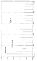
- the actual noise current of a DC-DC converter is shown in FIG.
- the triangular current is represented by means of a Fourier analysis as a frequency spectrum.
- the fundamental wave is 50 kHz / 1A and the strongest harmonic is 150 kHz / 0.1 A.
- the required chokes are much smaller than a conventional filter that must be designed for the 50 kHz fundamental.
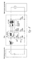
- the inventive filter hereinafter called FRC (F eedback R ipple ompensation C) consists of three LC stages.
- the auxiliary voltage source U H is generated by the inductor L3 (secondary winding W2) and coupled via the resistors R4, R3 to the capacitor C1.
- the necessary antiphase of U C1 and U H is achieved by the phase rotation of L3, C2, L2, C1, which is tuned to 180 ° at the frequency to be canceled (50 kHz).
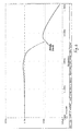
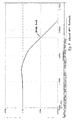
- the damping curve of the FRC is recorded in FIGS. 6 and 7.
- the 1 Aeff current is attenuated to 7 mA ( Figure 6).
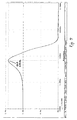
- the current increase in the resonant frequency of the FRC is 1.4 Aeff ( Figure 7).
- the prior art filter ( Figure 8) is designed according to the optimization guidelines of D. Venable, described in the article 'Minimizing Input Filter Requirements Power Supply Design' (PCIM May 1987).
- the 50 kHz The fundamental is attenuated from 1 Aeff to 9 mAeff ( Figure 9).
- the current increase in the resonance frequency (FIG. 10) is 1.4 Aeff.
- the FRC filter requires only 26% of the inductance of the venable filter (9 ⁇ H to 35 ⁇ H). This achieves the desired mass and volume savings.
Landscapes
- Engineering & Computer Science (AREA)
- Power Engineering (AREA)
- Filters And Equalizers (AREA)
- Power Conversion In General (AREA)
- Networks Using Active Elements (AREA)
- Amplifiers (AREA)
- Dc-Dc Converters (AREA)
Description
- Die Erfindung betrifft einen Gleichspannungswandler, der nach dem Schaltreglerprinzip arbeitet.
- Derartige Gleichspannungswandler erzeugen prinzipbedingt unerwünschte hochfrequente Wechselströme, die dem aufgenommenen Gleichstrom überlagert sind. Um eine speisende Gleichspannungsquelle vor diesen Störungen zu schützen, muß ein Filter, bestehend aus Drosseln und Kondensatoren, zwischen speisende Quelle und Gleichspannungswandler geschaltet werden.
Durch die gute Dämpfung von mehrstufigen L-C Filtern können die Störströme auf akzeptable Werte für die speisende Quelle abgeschwächt werden. - Bei allen Anwendungen und speziell beim Einsatz in der Luft- und Raumfahrt sind die voluminösen Drosseln und Kondensatoren unerwünscht, da sie die Baugröße und vor allem das Gewicht der Stromversorgungssysteme in die Höhe treiben.
- Die GB 904,482 betrifft einen elektrischen Filter mit Kondensatoren, welcher für Gleichstromkreise bereitgestellt wird. Die GB 904,482 beschreibt die Verwendung eines elektrischen Filters, wobei die Kondensatoren in Reihe mit einer Gleichspannungsquelle geschaltet sind und zwar so, dass die Gleichspannung, welche von den Kondensatoren aufgenommen wird, kleiner ist als die Spannung, welche auf den gesamten Filter angewendet wird.
- Die US 5,668,708 betrifft einen Gleichstromversorger mit einem niedrigen Welligkeitslevel für den Ausgabestrom. Die US 5,668,708 beschreibt einen Stormversorger, welcher eine Endstufe mit einem Filter enthält. Der beschriebene Stromversorger enthält weiterhin in seiner Endstufe einen Welligkeitsausscheider, welcher ein Mittel zur Messung des Welligkeitsstroms enthält, der durch den Filter fließt. Ein Strom von gleicher Größe, aber unterschiedlicher Polarität wird in den Ausgabestrom des Stromversorgers eingebracht, um wirksam die Welligkeit zu neutralisieren.
- Aufgabe der Erfindung ist es, das Volumen der Drosseln zu verringern, ohne die Dämpfungskennlinie des Filters soweit zu verändern, daß der wirksame Schutz gegen hochfrequente Störungen verlorengeht. Diese Aufgabe wird durch die Merkmale des Anspruchs 1 gelöst.
- Diese Aufgabe wird erfindungsgemäss durch den Gegenstand der Patentansprüche gelöst.
- Die Erfindung wird nachfolgend anhand von Figuren näher erläutert. Es zeigen:
- Fig. 1
- einen zum Stand der Technik gehörenden L-C L-C filter,
- Fig. 2
- einen L-C L-C Filter der ein Beispiel für die Lösung ist,
- Fig. 3
- den Störstrom eines Gleichspannungswandlers,
- Fig. 4
- das Frequenzspektrum des Wandler Störstromes,
- Fig. 5
- eine technische Ausführung des erfindungsgemässen Filters,
- Fig. 6
- die Dämpfungskurve (logaritmische Darstellung) des erfindungsgemässen Filters,
- Fig. 7
- die Dämpfungskurve (lineare Darstellung) des erfindungsgemässen Filters,
- Fig. 8
- eine technische Ausführung eines zum 'Stand der Technik' gehörenden Filters,
- Fig. 9
- die Dämpfungskurve (logaritmische Darstellung) des Filters von Fig. 8 und
- Fig. 10
- die Dämpfungskurve (lineare Darstellung) des zum 'Stand der Technik' gehörenden Filters.
- Fig. 1 zeigt die Standardkonfiguration eines herkömmlichen L-C L-C Filters. Der unerwünschte Störstrom IL1 wird von der Störspannung UC1 (Wechselspannungsanteil) durch die Drossel L1 getrieben. Der Gleichspannungsanteil von UC1 ist für die folgenden Betrachtungen nicht relevant und wird deshalb nicht weiter erwähnt. Reduziert man die Induktivitäten von L1 und L2, um Volumen und Masse einzusparen, so wird die Störspannung UC1 und somit auch der Störstrom IL1 größer und ist nicht mehr akzeptabel für die speisende Quelle.
- Ein Beispiel für die Lösung dieses Problems der das Verständnis der Erfindung erleichtert ist in Fig. 2 dargestellt. In Reihe zu C1 ist eine Hilfswechselspannungsquelle UH geschaltet. UH ist die gleiche Wechselspannungsamplitude wie die Störspannung UC1 bei 180° Phasendrehung.
- Durch die Gegenphasigkeit heben sich die beiden Spannungen gegenseitig auf, und die stromtreibende Wechselspannungskomponente am Eingang von L1 (Anschluß A) wird zu null, und somit wird auch der Störstrom IL1 zu null.
- Die komplette Auslöschung von IL1 funktioniert natürlich nur ideal unter der Annahme, daß der Gleichspannungswandler nur eine feste Störfrequenz ohne Oberwellen erzeugt.
- Der tatsächliche Störstrom eines Gleichspannungswandlers ist in Fig. 3 dargestellt. In Fig. 4 ist der dreieckförmige Strom mittels einer Fourier Analyse als Frequenzspektrum dargestellt. Die Grundwelle liegt bei 50 kHz/1A und die stärkste Oberwelle bei 150 kHz/0,1 A.
- Mit dem Prinzip der gegenphasigen Einkopplung einer 50 kHz Hilfsspannung kann nur die Grundwelle ausgelöscht werden. Zur Dämpfung der Oberwellen ist nach wie vor ein mehrstufiges L-C Filter notwendig.
- Da die Oberwellen nur noch kleine Amplituden bei hohen Frequenzen aufweisen, sind die benötigten Drosseln wesentlich kleiner als bei einem konventionellen Filter, das für die 50 kHz Grundwelle ausgelegt werden muß.
- In Fig. 5 ist die technische Realisierung des neuen und - zum Verlgeich in Fig. 8 - des zum Stand der Technik gehörenden Filters dargestellt. Beide Filter sollen die 50 kHz Grundwelle des Gleichspannungswandlers von 1 Aeff auf 10 mAeff abdämpfen. Die Stromüberhöhung in den Filter Resonanzfrequenzen muß mit zusätzlichen Widerständen in Reihe oder parallel zu Kondensatoren und Drosseln auf maximal 1,4 Aeff begrenzt werden.
- Das erfindungsgemässe Filter, im folgenden FRC (Feedback Ripple Compensation) genannt, besteht aus drei L-C Stufen. Die Hilfsspannungsquelle UH wird von der Drossel L3 (Sekundärwicklung W2) erzeugt und über die Widerstände R4, R3 am Kondensator C1 eingekoppelt. Die notwendige Gegenphasigkeit von UC1 und UH wird durch die Phasendrehung von L3, C2, L2, C1 erreicht, die bei der auszulöschenden Frequenz (50 kHz) auf 180° abgestimmt ist. Die Dämpfungskurve des FRC ist in den Fig. 6 und 7 aufgezeichnet. Bei der 50 kHz Grundwelle wird der 1 Aeff Strom auf 7 mA (Fig. 6) abgedämpft. Die Stromüberhöhung in der Resonanzfrequenz des FRC beträgt 1,4 Aeff (Fig. 7).
- Das zum Stand der Technik gehörende Filter (Fig. 8) ist nach den Optimierungsrichtlinien von D. Venable, die im Aufsatz 'Minimizing Input Filter Requirements Power Supply Design' (PCIM May 1987) beschrieben sind, ausgelegt. Die 50 kHz Grundwelle wird von 1 Aeff auf 9 mAeff (Fig. 9) abgedämpft. Die Stromüberhöhung in der Resonanzfrequenz (Fig. 10) beträgt 1,4 Aeff.
- In der folgenden Tabelle sind die Daten der beiden Filter gegenübergestellt.
Filter FRC-Filter Stand der Technik gemäss der Erfindung Dämpfung (soll > 100) 1 Aeff: 9 mAeff = 111 1A: 7 mA = 143 Resonanzüberhöhung 1,4 A 1,4 A Gesamtkapazität C1 + C2 C1 + C1 + C3 100 µF 100 µF Gesamtinduktivität L1 + L2 L1 + L2 + L3 35 µH 9 µH - Bei ca. gleicher Grundwellendämpfung und gleicher Kapazität benötigt das FRC-Filter nur 26 % der Induktivität des Venable Filters (9 µH zu 35 µH). Hiermit wird die gewünschte Masse- und Volumeneinsparung erreicht.
Claims (1)
- Filter für Gleichspannungswandler, mit drei L-C-Stufen (L1-C1, L2-C2, L3-C3), wobei
der Filter zwischen eine speisende Quelle und den Gleichspannungswandler schaltbar ist, und in Reihe zu einem Kondensator (C1) der L-C-Stufe, die mit der speisenden Quelle direkt verbindbar ist (L1-C1), eine Hilfswechselspannungsquelle (UH) geschaltet ist, die die gleiche Wechselspannungsamplitude wie eine durch den Kondensator hervorgerufene Störspannung (UC1) bei 180°-Phasendrehung aufweist, und wobei
die Hilfswechselspannungsquelle (UH) von einer Sekundärwicklung (W2) der Induktivität (L3) der L-C-Stufe, die mit dem Gleichspannungswandler direkt verbindbar ist (L3-C3), erzeugt wird;
die Sekundärwicklung (W2) der Induktivität (L3) mit einem hierzu seriell geschalteten Widerstand (R4) parallel mit einem in Serie zu dem Kondensator (C1) geschalteten Widerstand (R3) verbunden wird; und
das Verhältnis der Windungszahlen der Primärwicklung (W1) und der Sekundärwicklung (W2) gleich ist.
Applications Claiming Priority (2)
| Application Number | Priority Date | Filing Date | Title |
|---|---|---|---|
| DE19855439 | 1998-11-27 | ||
| DE19855439A DE19855439C2 (de) | 1998-11-27 | 1998-11-27 | Filter für Gleichspannungswandler |
Publications (3)
| Publication Number | Publication Date |
|---|---|
| EP1005146A2 EP1005146A2 (de) | 2000-05-31 |
| EP1005146A3 EP1005146A3 (de) | 2003-09-03 |
| EP1005146B1 true EP1005146B1 (de) | 2006-06-07 |
Family
ID=7889654
Family Applications (1)
| Application Number | Title | Priority Date | Filing Date |
|---|---|---|---|
| EP99117841A Expired - Lifetime EP1005146B1 (de) | 1998-11-27 | 1999-09-10 | Filter für Gleichspannungswandler |
Country Status (6)
| Country | Link |
|---|---|
| US (1) | US6166931A (de) |
| EP (1) | EP1005146B1 (de) |
| AT (1) | ATE329400T1 (de) |
| DE (2) | DE19855439C2 (de) |
| DK (1) | DK1005146T3 (de) |
| ES (1) | ES2262280T3 (de) |
Families Citing this family (3)
| Publication number | Priority date | Publication date | Assignee | Title |
|---|---|---|---|---|
| FR2803135B1 (fr) * | 1999-12-28 | 2002-04-26 | Valeo Electronique | Circuit a decoupage, notamment pour vehicule automobile, a filtrage ameliore |
| US20070115085A1 (en) * | 2005-11-18 | 2007-05-24 | Hamilton Sundstrand Corporation | Direct current link inductor for power source filtration |
| US10230296B2 (en) * | 2016-09-21 | 2019-03-12 | Express Imaging Systems, Llc | Output ripple reduction for power converters |
Family Cites Families (13)
| Publication number | Priority date | Publication date | Assignee | Title |
|---|---|---|---|---|
| CH374416A (de) * | 1959-11-20 | 1964-01-15 | Bbc Brown Boveri & Cie | Elektrisches Filter für Gleichstromkreise |
| US3340458A (en) * | 1964-06-16 | 1967-09-05 | Roy M Keller | Filter choke with self-desaturating magnetic core |
| US4262328A (en) * | 1979-08-03 | 1981-04-14 | Litton Systems, Inc. | DC-to-DC converter |
| US4298924A (en) * | 1979-10-01 | 1981-11-03 | Honeywell Information Systems Inc. | Switching regulator circuit with phase shift subtraction |
| US4594648A (en) * | 1984-11-28 | 1986-06-10 | Venus Scientific Inc. | Wide frequency band coupling network for an active ripple and noise filter |
| US4795959A (en) * | 1985-04-22 | 1989-01-03 | Lesco Development | Harmonic inductor for generation of an energy conserving power wave |
| US4710861A (en) * | 1986-06-03 | 1987-12-01 | Martin Kanner | Anti-ripple circuit |
| GB8714755D0 (en) * | 1987-06-24 | 1987-07-29 | Gen Electric | Filter |
| US4888675A (en) * | 1987-08-26 | 1989-12-19 | Harris Corporation | Switching power supply filter |
| US5227962A (en) * | 1991-03-06 | 1993-07-13 | Constant Velocity Transmission Lines, Inc. | Filter and power factor compensation network |
| US5345375A (en) * | 1991-12-16 | 1994-09-06 | Regents Of The University Of Minnesota | System and method for reducing harmonic currents by current injection |
| DE19509329C1 (de) * | 1995-03-15 | 1996-11-28 | Siemens Ag | Schaltungsanordnung |
| US5668708A (en) * | 1996-03-13 | 1997-09-16 | Spellman High Voltage Electronics Corp. | DC power supply with reduced ripple |
-
1998
- 1998-11-27 DE DE19855439A patent/DE19855439C2/de not_active Expired - Fee Related
-
1999
- 1999-09-10 ES ES99117841T patent/ES2262280T3/es not_active Expired - Lifetime
- 1999-09-10 EP EP99117841A patent/EP1005146B1/de not_active Expired - Lifetime
- 1999-09-10 AT AT99117841T patent/ATE329400T1/de not_active IP Right Cessation
- 1999-09-10 DK DK99117841T patent/DK1005146T3/da active
- 1999-09-10 DE DE59913518T patent/DE59913518D1/de not_active Expired - Fee Related
- 1999-11-29 US US09/449,490 patent/US6166931A/en not_active Expired - Fee Related
Also Published As
| Publication number | Publication date |
|---|---|
| US6166931A (en) | 2000-12-26 |
| DE59913518D1 (de) | 2006-07-20 |
| DE19855439C2 (de) | 2000-09-21 |
| DK1005146T3 (da) | 2006-07-10 |
| ATE329400T1 (de) | 2006-06-15 |
| DE19855439A1 (de) | 2000-06-15 |
| EP1005146A2 (de) | 2000-05-31 |
| EP1005146A3 (de) | 2003-09-03 |
| ES2262280T3 (es) | 2006-11-16 |
Similar Documents
| Publication | Publication Date | Title |
|---|---|---|
| DE3751020T2 (de) | Einrichtung für die Unterdrückung von Oberwellen. | |
| US5910889A (en) | Hybrid active power filter with programmed impedance characteristics | |
| DE19533556C1 (de) | Dreiphasen-Gleichrichterschaltung | |
| DE10392856T5 (de) | Aktiver Emi Filter | |
| DE19736786A1 (de) | U-Umrichter | |
| DE102005019215B4 (de) | Ausgangsfilter für einen gepulsten Stromrichter | |
| DE19547969C1 (de) | Elektrisches Filter | |
| DE19700100C2 (de) | Tiefsetzsteller | |
| US4743873A (en) | Highpass filter of a filter arrangement for a three-phase network connected to converters | |
| EP1005146B1 (de) | Filter für Gleichspannungswandler | |
| CH713573B1 (de) | Magnetische Drossel, Umrichterabschnitt und Umrichter. | |
| WO1999049559A2 (de) | Verfahren und vorrichtung zur entstörung von umrichtern | |
| DE102005028672A1 (de) | Glättungsschaltung zur Verbesserung der EMV | |
| DE4441214C2 (de) | Aktive Filterschaltung | |
| EP1248344B1 (de) | Reaktanz-Zweipolschaltung für nichtlineare Verbraucher | |
| DE3038714C2 (de) | ||
| DE102018010146A1 (de) | Vorrichtung zur Filterung von hochfrequenten Störspannungen in einer Schaltung zur Leistungsfaktorkorrektur | |
| DE4437560A1 (de) | Schaltung zur Kompensation von Wechselspannungsanteilen in einer Gleichspannung | |
| EP0440852B1 (de) | Steuerverfahren und Steuersatz zur Dämpfung von Resonanzschwingungen eines Parallelschwingkreises für einen Pulswechselrichter eines Stromzwischenkreisumrichters | |
| DE3012747A1 (de) | Netzteil mit wechselspannungseingang und gleichrichtern | |
| EP0970560A1 (de) | Schaltungsanordnung | |
| DE102019123197A1 (de) | Elektrische Komponente | |
| DE3342011C2 (de) | Tiefpaßfilter für elektrische Verbraucher | |
| DE19647933A1 (de) | Leistungselektronische Schaltungsanordnung | |
| DE2718598C2 (de) | Störstromreduzierende Stromrichterbeschaltung |
Legal Events
| Date | Code | Title | Description |
|---|---|---|---|
| PUAI | Public reference made under article 153(3) epc to a published international application that has entered the european phase |
Free format text: ORIGINAL CODE: 0009012 |
|
| AK | Designated contracting states |
Kind code of ref document: A2 Designated state(s): AT BE CH CY DE DK ES FI FR GB GR IE IT LI LU MC NL PT SE |
|
| AX | Request for extension of the european patent |
Free format text: AL;LT;LV;MK;RO;SI |
|
| RAP1 | Party data changed (applicant data changed or rights of an application transferred) |
Owner name: ASTRIUM GMBH |
|
| PUAL | Search report despatched |
Free format text: ORIGINAL CODE: 0009013 |
|
| AK | Designated contracting states |
Kind code of ref document: A3 Designated state(s): AT BE CH CY DE DK ES FI FR GB GR IE IT LI LU MC NL PT SE |
|
| AX | Request for extension of the european patent |
Extension state: AL LT LV MK RO SI |
|
| RIC1 | Information provided on ipc code assigned before grant |
Ipc: 7H 02M 1/15 B Ipc: 7H 02M 1/14 A |
|
| 17P | Request for examination filed |
Effective date: 20031205 |
|
| AKX | Designation fees paid |
Designated state(s): AT BE CH CY DE DK ES FI FR GB GR IE IT LI LU MC NL PT SE |
|
| RAP1 | Party data changed (applicant data changed or rights of an application transferred) |
Owner name: EADS ASTRIUM GMBH |
|
| 17Q | First examination report despatched |
Effective date: 20040519 |
|
| GRAP | Despatch of communication of intention to grant a patent |
Free format text: ORIGINAL CODE: EPIDOSNIGR1 |
|
| GRAS | Grant fee paid |
Free format text: ORIGINAL CODE: EPIDOSNIGR3 |
|
| GRAA | (expected) grant |
Free format text: ORIGINAL CODE: 0009210 |
|
| AK | Designated contracting states |
Kind code of ref document: B1 Designated state(s): AT BE CH CY DE DK ES FI FR GB GR IE IT LI LU MC NL PT SE |
|
| PG25 | Lapsed in a contracting state [announced via postgrant information from national office to epo] |
Ref country code: NL Free format text: LAPSE BECAUSE OF FAILURE TO SUBMIT A TRANSLATION OF THE DESCRIPTION OR TO PAY THE FEE WITHIN THE PRESCRIBED TIME-LIMIT Effective date: 20060607 Ref country code: IE Free format text: LAPSE BECAUSE OF FAILURE TO SUBMIT A TRANSLATION OF THE DESCRIPTION OR TO PAY THE FEE WITHIN THE PRESCRIBED TIME-LIMIT Effective date: 20060607 Ref country code: FI Free format text: LAPSE BECAUSE OF FAILURE TO SUBMIT A TRANSLATION OF THE DESCRIPTION OR TO PAY THE FEE WITHIN THE PRESCRIBED TIME-LIMIT Effective date: 20060607 |
|
| REG | Reference to a national code |
Ref country code: GB Ref legal event code: FG4D Free format text: NOT ENGLISH |
|
| REG | Reference to a national code |
Ref country code: CH Ref legal event code: EP |
|
| REG | Reference to a national code |
Ref country code: DK Ref legal event code: T3 |
|
| GBT | Gb: translation of ep patent filed (gb section 77(6)(a)/1977) |
Effective date: 20060621 |
|
| REG | Reference to a national code |
Ref country code: IE Ref legal event code: FG4D Free format text: LANGUAGE OF EP DOCUMENT: GERMAN |
|
| REF | Corresponds to: |
Ref document number: 59913518 Country of ref document: DE Date of ref document: 20060720 Kind code of ref document: P |
|
| PG25 | Lapsed in a contracting state [announced via postgrant information from national office to epo] |
Ref country code: SE Free format text: LAPSE BECAUSE OF FAILURE TO SUBMIT A TRANSLATION OF THE DESCRIPTION OR TO PAY THE FEE WITHIN THE PRESCRIBED TIME-LIMIT Effective date: 20060907 |
|
| PG25 | Lapsed in a contracting state [announced via postgrant information from national office to epo] |
Ref country code: MC Free format text: LAPSE BECAUSE OF NON-PAYMENT OF DUE FEES Effective date: 20060930 Ref country code: LI Free format text: LAPSE BECAUSE OF NON-PAYMENT OF DUE FEES Effective date: 20060930 Ref country code: CH Free format text: LAPSE BECAUSE OF NON-PAYMENT OF DUE FEES Effective date: 20060930 |
|
| PG25 | Lapsed in a contracting state [announced via postgrant information from national office to epo] |
Ref country code: PT Free format text: LAPSE BECAUSE OF FAILURE TO SUBMIT A TRANSLATION OF THE DESCRIPTION OR TO PAY THE FEE WITHIN THE PRESCRIBED TIME-LIMIT Effective date: 20061107 |
|
| REG | Reference to a national code |
Ref country code: ES Ref legal event code: FG2A Ref document number: 2262280 Country of ref document: ES Kind code of ref document: T3 |
|
| NLV1 | Nl: lapsed or annulled due to failure to fulfill the requirements of art. 29p and 29m of the patents act | ||
| REG | Reference to a national code |
Ref country code: IE Ref legal event code: FD4D |
|
| ET | Fr: translation filed | ||
| PLBE | No opposition filed within time limit |
Free format text: ORIGINAL CODE: 0009261 |
|
| STAA | Information on the status of an ep patent application or granted ep patent |
Free format text: STATUS: NO OPPOSITION FILED WITHIN TIME LIMIT |
|
| REG | Reference to a national code |
Ref country code: CH Ref legal event code: PL |
|
| 26N | No opposition filed |
Effective date: 20070308 |
|
| PG25 | Lapsed in a contracting state [announced via postgrant information from national office to epo] |
Ref country code: AT Free format text: LAPSE BECAUSE OF NON-PAYMENT OF DUE FEES Effective date: 20060910 |
|
| PG25 | Lapsed in a contracting state [announced via postgrant information from national office to epo] |
Ref country code: GR Free format text: LAPSE BECAUSE OF FAILURE TO SUBMIT A TRANSLATION OF THE DESCRIPTION OR TO PAY THE FEE WITHIN THE PRESCRIBED TIME-LIMIT Effective date: 20060908 |
|
| PG25 | Lapsed in a contracting state [announced via postgrant information from national office to epo] |
Ref country code: LU Free format text: LAPSE BECAUSE OF NON-PAYMENT OF DUE FEES Effective date: 20060910 |
|
| PGFP | Annual fee paid to national office [announced via postgrant information from national office to epo] |
Ref country code: DK Payment date: 20080912 Year of fee payment: 10 |
|
| PG25 | Lapsed in a contracting state [announced via postgrant information from national office to epo] |
Ref country code: CY Free format text: LAPSE BECAUSE OF FAILURE TO SUBMIT A TRANSLATION OF THE DESCRIPTION OR TO PAY THE FEE WITHIN THE PRESCRIBED TIME-LIMIT Effective date: 20060607 |
|
| PGFP | Annual fee paid to national office [announced via postgrant information from national office to epo] |
Ref country code: FR Payment date: 20080912 Year of fee payment: 10 Ref country code: IT Payment date: 20080924 Year of fee payment: 10 |
|
| PGFP | Annual fee paid to national office [announced via postgrant information from national office to epo] |
Ref country code: GB Payment date: 20080918 Year of fee payment: 10 |
|
| PGFP | Annual fee paid to national office [announced via postgrant information from national office to epo] |
Ref country code: DE Payment date: 20080919 Year of fee payment: 10 |
|
| PGFP | Annual fee paid to national office [announced via postgrant information from national office to epo] |
Ref country code: ES Payment date: 20080929 Year of fee payment: 10 |
|
| PGFP | Annual fee paid to national office [announced via postgrant information from national office to epo] |
Ref country code: BE Payment date: 20081001 Year of fee payment: 10 |
|
| BERE | Be: lapsed |
Owner name: *EADS ASTRIUM G.M.B.H. Effective date: 20090930 |
|
| REG | Reference to a national code |
Ref country code: DK Ref legal event code: EBP |
|
| GBPC | Gb: european patent ceased through non-payment of renewal fee |
Effective date: 20090910 |
|
| REG | Reference to a national code |
Ref country code: FR Ref legal event code: ST Effective date: 20100531 |
|
| PG25 | Lapsed in a contracting state [announced via postgrant information from national office to epo] |
Ref country code: FR Free format text: LAPSE BECAUSE OF NON-PAYMENT OF DUE FEES Effective date: 20090930 Ref country code: DE Free format text: LAPSE BECAUSE OF NON-PAYMENT OF DUE FEES Effective date: 20100401 |
|
| PG25 | Lapsed in a contracting state [announced via postgrant information from national office to epo] |
Ref country code: BE Free format text: LAPSE BECAUSE OF NON-PAYMENT OF DUE FEES Effective date: 20090930 |
|
| PG25 | Lapsed in a contracting state [announced via postgrant information from national office to epo] |
Ref country code: GB Free format text: LAPSE BECAUSE OF NON-PAYMENT OF DUE FEES Effective date: 20090910 |
|
| PG25 | Lapsed in a contracting state [announced via postgrant information from national office to epo] |
Ref country code: DK Free format text: LAPSE BECAUSE OF NON-PAYMENT OF DUE FEES Effective date: 20090930 |
|
| PG25 | Lapsed in a contracting state [announced via postgrant information from national office to epo] |
Ref country code: IT Free format text: LAPSE BECAUSE OF NON-PAYMENT OF DUE FEES Effective date: 20090910 |
|
| REG | Reference to a national code |
Ref country code: ES Ref legal event code: FD2A Effective date: 20110714 |
|
| PG25 | Lapsed in a contracting state [announced via postgrant information from national office to epo] |
Ref country code: ES Free format text: LAPSE BECAUSE OF NON-PAYMENT OF DUE FEES Effective date: 20110704 |
|
| PG25 | Lapsed in a contracting state [announced via postgrant information from national office to epo] |
Ref country code: ES Free format text: LAPSE BECAUSE OF NON-PAYMENT OF DUE FEES Effective date: 20090911 |