EP1004552A1 - Panneau de verre, procede de fabrication et espaceur pour ce panneau de verre - Google Patents
Panneau de verre, procede de fabrication et espaceur pour ce panneau de verre Download PDFInfo
- Publication number
- EP1004552A1 EP1004552A1 EP99918277A EP99918277A EP1004552A1 EP 1004552 A1 EP1004552 A1 EP 1004552A1 EP 99918277 A EP99918277 A EP 99918277A EP 99918277 A EP99918277 A EP 99918277A EP 1004552 A1 EP1004552 A1 EP 1004552A1
- Authority
- EP
- European Patent Office
- Prior art keywords
- glass
- spacer
- forming
- spacers
- glass sheet
- Prior art date
- Legal status (The legal status is an assumption and is not a legal conclusion. Google has not performed a legal analysis and makes no representation as to the accuracy of the status listed.)
- Withdrawn
Links
Images


Classifications
-
- E—FIXED CONSTRUCTIONS
- E06—DOORS, WINDOWS, SHUTTERS, OR ROLLER BLINDS IN GENERAL; LADDERS
- E06B—FIXED OR MOVABLE CLOSURES FOR OPENINGS IN BUILDINGS, VEHICLES, FENCES OR LIKE ENCLOSURES IN GENERAL, e.g. DOORS, WINDOWS, BLINDS, GATES
- E06B3/00—Window sashes, door leaves, or like elements for closing wall or like openings; Layout of fixed or moving closures, e.g. windows in wall or like openings; Features of rigidly-mounted outer frames relating to the mounting of wing frames
- E06B3/66—Units comprising two or more parallel glass or like panes permanently secured together
- E06B3/6612—Evacuated glazing units
-
- C—CHEMISTRY; METALLURGY
- C03—GLASS; MINERAL OR SLAG WOOL
- C03C—CHEMICAL COMPOSITION OF GLASSES, GLAZES OR VITREOUS ENAMELS; SURFACE TREATMENT OF GLASS; SURFACE TREATMENT OF FIBRES OR FILAMENTS MADE FROM GLASS, MINERALS OR SLAGS; JOINING GLASS TO GLASS OR OTHER MATERIALS
- C03C27/00—Joining pieces of glass to pieces of other inorganic material; Joining glass to glass other than by fusing
- C03C27/06—Joining glass to glass by processes other than fusing
-
- E—FIXED CONSTRUCTIONS
- E06—DOORS, WINDOWS, SHUTTERS, OR ROLLER BLINDS IN GENERAL; LADDERS
- E06B—FIXED OR MOVABLE CLOSURES FOR OPENINGS IN BUILDINGS, VEHICLES, FENCES OR LIKE ENCLOSURES IN GENERAL, e.g. DOORS, WINDOWS, BLINDS, GATES
- E06B3/00—Window sashes, door leaves, or like elements for closing wall or like openings; Layout of fixed or moving closures, e.g. windows in wall or like openings; Features of rigidly-mounted outer frames relating to the mounting of wing frames
- E06B3/66—Units comprising two or more parallel glass or like panes permanently secured together
- E06B3/663—Elements for spacing panes
- E06B3/66304—Discrete spacing elements, e.g. for evacuated glazing units
-
- Y—GENERAL TAGGING OF NEW TECHNOLOGICAL DEVELOPMENTS; GENERAL TAGGING OF CROSS-SECTIONAL TECHNOLOGIES SPANNING OVER SEVERAL SECTIONS OF THE IPC; TECHNICAL SUBJECTS COVERED BY FORMER USPC CROSS-REFERENCE ART COLLECTIONS [XRACs] AND DIGESTS
- Y02—TECHNOLOGIES OR APPLICATIONS FOR MITIGATION OR ADAPTATION AGAINST CLIMATE CHANGE
- Y02A—TECHNOLOGIES FOR ADAPTATION TO CLIMATE CHANGE
- Y02A30/00—Adapting or protecting infrastructure or their operation
- Y02A30/24—Structural elements or technologies for improving thermal insulation
- Y02A30/249—Glazing, e.g. vacuum glazing
-
- Y—GENERAL TAGGING OF NEW TECHNOLOGICAL DEVELOPMENTS; GENERAL TAGGING OF CROSS-SECTIONAL TECHNOLOGIES SPANNING OVER SEVERAL SECTIONS OF THE IPC; TECHNICAL SUBJECTS COVERED BY FORMER USPC CROSS-REFERENCE ART COLLECTIONS [XRACs] AND DIGESTS
- Y02—TECHNOLOGIES OR APPLICATIONS FOR MITIGATION OR ADAPTATION AGAINST CLIMATE CHANGE
- Y02B—CLIMATE CHANGE MITIGATION TECHNOLOGIES RELATED TO BUILDINGS, e.g. HOUSING, HOUSE APPLIANCES OR RELATED END-USER APPLICATIONS
- Y02B80/00—Architectural or constructional elements improving the thermal performance of buildings
- Y02B80/22—Glazing, e.g. vaccum glazing
Definitions
- the present invention relates to a glass panel for improving heat insulating performance.
- the invention relates, more particularly, to a glass panel formed by assembling together a plurality of glass sheets with a plurality of spacers being interposed therebetween for forming a space and with outer peripheral edges of the plurality of glass sheets being sealed, and a method of manufacturing such glass panel, and relates further to the spacer for use in such glass panel.
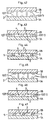
- such glass panel as shown in Figs. 48 and 49 for instance, is manufactured by disposing a plurality of spacers 5 made of cylindrical glass prepared in the form of spacers at predetermined positions on a spacer-disposing face 2A of a first glass sheet 1A, superposing a second glass sheet 1B thereon, and sealing outer peripheral edges 3 of the two glass sheets with a sealing material S made of low-melting glass.
- the inside of the space 4 is maintained under a pressure-reduced condition, in order to enhance the heat insulating performance and sound insulating performance.
- the great number of spacers 5 are interposed between the first glass sheet 1A and the second glass sheet 1B so as to allow the atmospheric pressure acting on the outer surface of the first glass sheet 1A or second glass sheet 1B to be substantially uniformly born by the entire glass sheets, whereby breakage or cracking of the first glass sheet 1A and second glass sheet 1B may be avoided.
- the second glass sheet 1B is superposed thereon.
- the disposing operation of the spacers 5 at predetermined positions on the first glass sheet 1A is done by a worker's manual operation of disposing the spacers 5 one by one on the first glass sheet 1A or by using a suction-conveying device operable to suck the plurality of spacers (5) to be disposed within a predetermined area at one time and then to place them on the first glass sheet 1A.
- spacers 5 need to be manufactured in advance and these spacers 5 need to be placed with a predetermined distance therebetween on the sheet face of the first glass sheet 1A. Moreover, a separate operation is needed for bonding these spacers 5 on the first glass sheet so as to prevent movement of the spacers. Hence, the handling of the spacers 5 would be troublesome and the manufacturing process of the glass panel would be complicated.
- the mere disposing operation of the spacers 5 on the first glass sheet 1A cannot prevent inadvertent displacement or tumbling of the spacers 5 in the course of the superposing operation of the second glass sheet 1B unless the spacers 5 are fixed in advance. Therefore, the superposing operation of the two glass sheets 1A, 1B is troublesome, hence, the productivity is poor. Then, it is conceivable to bond the spacers 5 on the first glass sheet 1A. However, it is not easy to bond such great number of small objects.
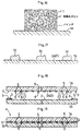
- the convention has proposed an alternative method (e.g. the European patent Serial No. 0047725), in which case spacer-forming paste 11 which is prepared by mixing together low-melting glass frit and caking additive is caused to adhere, in the form of paste-formed members 10 having predetermined dimensions, to the respective predetermined positions on the two glass sheets 1A, 1B (see Fig. 42), then after placing the leading ends of these paste-formed members 10 into abutment with each other, the members are baked (see Fig. 43), so as to be combined together into the spacers 5, and also these spacers 5 are bonded to the respective glass sheets 1A, 1B (see Fig. 44).
- spacer-forming paste 11 which is prepared by mixing together low-melting glass frit and caking additive is caused to adhere, in the form of paste-formed members 10 having predetermined dimensions, to the respective predetermined positions on the two glass sheets 1A, 1B (see Fig. 42)
- the members are baked (see Fig. 43), so as to be combined together into the spacer
- the two glass sheets 1A, 1B after being assembled together are completely restricted in position relative to each other by means of the spacers 5. Then, if there occurs deformation of the glass panel, such as warping thereof, due to an external force, e.g. wind pressure, acting on the glass panel, this will cause mutual displacement between the two glass sheets 1A, 1B, so that the spacers 5 may be broken or the glass sheets 1 may be damaged.
- the present invention has been made in view of the above-described state of the art and its object is to provide a glass panel which is easy to manufacture and has superior productivity and which can prevent damage of the glass sheets and a method of manufacturing such glass panel and also to provide spacers for use in such glass panel.
- the characterizing features of the glass panel according to the present invention are as follows.
- a glass panel relating to claim 1, as shown mainly in Fig. 9, comprises a pair of first and second glass sheets disposed with sheet faces thereof opposed to each other, a plurality of spacers interposed between the pair of glass sheets for forming a space therebetween, and a sealing glass for bonding peripheral edges of the glass sheets together for sealing the space, the sealing glass having a fusing temperature lower than a softening point of the glass sheets, wherein each spacer is formed by disposing spacer-forming paste in a predetermined shape on the sheet face of the glass sheet and then baking the paste, said spacer-forming paste containing glass component which has a fusing temperature lower than the softening point of the glass sheets and a softening point higher than a fusing temperature of the sealing glass.
- the spacer fused to glass sheets may be formed by disposing the spacer-forming paste containing a glass component having a lower fusing temperature than the softening point of the glass sheets in a predetermined shape on the sheet face of the glass sheet and then baking this paste.
- the spacers may be easily bonded and fixed in position with a predetermined distance therebetween on the sheet face of the glass sheets.
- the glass component contained in the paste has a softening point higher than the fusing temperature of the sealing glass, there is no risk of the spacers being softened and deformed when the sealing glass is heated for bonding together the peripheral edges of the two glass sheets.
- the distance between the two glass sheets may be maintained properly, so that a desired heat-insulating performance may be readily assured.
- a glass panel relating to claim 2, as shown in Figs. 1-5, is characterized in that the spacer is formed by baking the paste which is disposed on the sheet face of the first glass sheet alone.
- a glass panel relating to claim 3 is characterized in that the glass component contained in the paste has a lower lead content and a higher silicon content than the sealing glass.
- a method of manufacturing a glass panel relating to claim 4 comprises the steps of: preparing spacer-forming paste capable of forming spacers; forming and disposing the spacer-forming paste in a predetermined shape on the space-side face, i.e. spacer-disposing face, of a first glass sheet; subsequently effecting a predetermined solidifying operation on each spacer-forming paste so as to form a plurality of pre-spacer forming elements; effecting a height-adjusting shaping operation on respective contacting ends capable of contacting a second glass sheet of the plurality of solidified pre-spacer forming elements into a predetermined height relative to the spacer-disposing face; and assembling the second glass sheet with the first glass sheet with a space-side face of the second glass sheet being opposed to the height-adjusted shaped contacting ends.
- the manufacture of the glass panel may be facilitated and also the damage of the glass panel may be avoided. That is, because the spacer-forming paste is disposed on the spacer-disposing face, i.e. the space-side face, of the first glass sheet, the assembling operation of the two glass sheets does not require precise mutual positioning. This is because the spacers may only be distributed properly on the spacer-disposing face. Further, the spacer-forming paste is subjected to the predetermined solidifying operation (e.g. a baking operation in case e.g. a low-melting glass paste is employed) to be formed into the spacers. Then, if each of these spacers is subjected to the height-adjusting shaping operation (e.g.
- the predetermined solidifying operation e.g. a baking operation in case e.g. a low-melting glass paste is employed
- the contacting ends of the pre-spacer forming elements after the baking operation thereof will be heated again and pressed at the softening temperature) to obtain a predetermined height relative to the spacer-disposing face, when the second glass sheet is assembled by sealing the outer peripheral edges, there will occur no such trouble of only a limited number of the spacers coming into contact with the second glass sheet.
- a glass panel having a stable construction As the spacers are not bonded to the space-side face of the second glass sheet, relative movement is allowed between the spacers and the second glass sheet. Accordingly, deformation, e.g. warping, of the glass panel may be effectively absorbed through the mutual displacement between the spacers and the second glass sheet.
- a glass panel manufacturing method relating to claim 5, as shown in Fig. 8 for instance, is characterized in that the height-adjusted, shaped contacting end of the spacer in claim 4 is then subjected to a grinding operation to form convex and concave portions at this contacting end.
- the heat-transfer resistance between the spacer and the second glass sheet may be enhanced, thereby to restrict heat conduction via the spacer.
- stress concentration may be avoided for effectively preventing development of cracks in the glass sheet.
- the contact area of the contact portions relative to the second glass sheet may be reduced. Moreover, since substantially entire area of the contacting end including the concave portions of the contacting end of the spacer functions as the contact area for contacting the second glass sheet, it becomes possible to avoid stress concentration to the second glass sheet. Further, with such reduced contact area, it becomes also possible to increase the heat-transfer resistance between the second glass sheet and the spacer.
- a method of manufacturing a glass panel relating to claim 6, as illustrated in Figs. 1 through 7, comprises the steps of: preparing spacer-forming paste capable of forming spacers; forming and disposing the spacer-forming paste in a predetermined shape on the space-side face, i.e. spacer-disposing face, of a first glass sheet (see Fig. 3); subsequently effecting a predetermined semi-solidifying operation on each spacer-forming paste so as to form a plurality of semi-solidified pre-spacer forming elements (see Fig.
- the manufacture of the glass panel may be facilitated and also the damage of the glass panel may be avoided. That is, as illustrated in Figs. 1 through 7, because the spacer-forming paste is disposed on the spacer-disposing face, i.e. the space-side face, of the first glass sheet, the assembling operation of the two glass sheets does not require precise mutual positioning. This is because the spacers may only be distributed properly on the spacer-disposing face. Further, the spacer-forming paste is subjected to the predetermined semi-solidifying operation (e.g.
- the paste is baked and then is maintained at a temperature higher than the softening point so as to maintain its semi-solidified state) to be formed into the semi-solidified pre-spacer forming elements. Then, if each of these is subjected to the height-adjusting shaping operation (the pre-spacer forming element is pressed, under a temperature condition in which the element is slightly softened, by the space-side face of the second glass sheet, so as to form it simultaneously with the assembly operation thereof to the first glass sheet and the sealing operation of the outer peripheral edges) to obtain a predetermined height relative to the spacer-disposing face, when the second glass sheet is assembled by sealing the outer peripheral edges, there will occur no such trouble of only a limited number of the contacting ends coming into contact with the second glass sheet. As a result, there may be obtained a glass panel having a stable construction.
- the spacers are not bonded to the space-side face of the second glass sheet, the contacting end of the spacer and the space-side face of the second glass sheet are free from each other, so that relative movement is allowed between the spacers and the second glass sheet. Accordingly, deformation, e.g. warping, of the glass panel may be effectively absorbed through the mutual displacement between the spacers and the second glass sheet.
- a glass panel manufacturing method relating to claim 7, as illustrated in Figs. 1 through 5 for instance, is characterized in that the spacer-forming paste is mixed by adding a binder to the low-melting glass having a lower fusing temperature than the softening point of the glass sheet in any one of claims 4 through 6; this spacer-forming paste is baked under a predetermined baking temperature together with the first glass sheet to be formed into the plurality of pre-space forming elements; and the contacting ends are height-adjusted by pressing while these pre-spacer forming elements are maintained at the softening temperature of the pre-spacer forming elements which is lower than the baking temperature.
- the fusing temperature of the low-melting glass refers to such a temperature as the viscosity of the low-melting glass becomes fluidized, e.g. the viscosity becomes below 10 5 poise.
- the spacer may be formed into the predetermined shape while this spacer is fused to the second glass sheet.
- the pre-spacer forming elements fused to the second glass sheet may be formed by baking the spacer-forming paste comprising the low-melting glass having a fusing temperature lower than the softening point of the glass sheets. Therefore, it is possible then to effect the height-adjusting shaping operation of the spacer by pressing the pre-spacer forming element while it is maintained at its softening temperature which is lower than the baking temperature.
- a glass panel manufacturing method relating to claim 8, as illustrated in Fig. 10 for instance, is characterized in that the spacer-forming paste is prepared by adding to the low-melting glass particles of convex forming elements having a heat-resistant temperature higher than the softening temperature of the pre-spacer forming elements in claim 7 and mixing them together.
- the convex forming element has a higher softening point than the fusing temperature of the pre-spacer forming element comprised of the low-melting glass constituting the spacer-forming paste, the particles of the convex forming elements can form convex portions on the surface of the contacting end of the spacer, when the low-melting glass is solidified.
- a glass panel manufacturing method relating to claim 9, is characterized in that in the height-adjusting shaping step of the contacting end according to any one of claims 4-7, the contacting end is shaped into a flat smooth face as shown in Figs. 1 through 5 for instance.
- each spacer for contacting the second glass sheet is formed as a flat smooth face, the sliding resistance of the contacting end against the space-side face of the second glass sheet is reduced, so that they may readily slide against each other in the case of deformation of the glass panel.
- the external force affecting the spacer during deformation of the glass panel may be reduced advantageously.
- the height-adjusting shaping operation of the pre-spacer forming element may be carried out simply by pressing it into a flat surface. Therefore, this shaping operation may be very easy.
- a glass panel manufacturing method relating to claim 10, as shown in Figs. 2 and 7 for instance, comprises the steps of: preparing spacer-forming paste capable of forming spacers; forming and disposing the spacer-forming paste in a predetermined shape and at a plurality of predetermined positions on the space-side face, i.e. spacer-disposing face, of a first glass sheet; effecting a height-adjusting shaping operation (e.g.
- the manufacture of the glass panel may be facilitated and also the damage of the glass panel may be avoided.
- the spacer-forming paste is disposed on the spacer-disposing face, i.e. the space-side face, of the first glass sheet, the assembling operation of the two glass sheets does not require precise mutual positioning. This is because the spacers may only be distributed properly on the spacer-disposing face.
- the spacer-forming paste disposed on the spacer disposing face is formed into the predetermined shape while being height-adjusted so as to obtain a predetermined height relative to the spacer-disposing face (e.g. if the spacer-forming paste is height-adjusted by means of e.g. screen printing method in accordance with the thickness of the screen during the printing operation), then, when the spacers are formed by baking, there will occur no such inconvenience as only some of the contacting ends come into contact with the second glass sheet when the second glass sheet is assembled with sealing of the outer peripheral edges. As a result, there may be obtained a glass panel having a stable construction.
- spacers are not bonded to the space-side face of the second glass sheet, relative movement is allowed between the spacers and the second glass sheet. Accordingly, deformation, e.g. warping, of the glass panel may be effectively absorbed through the mutual displacement between the spacers and the second glass sheet.
- a glass panel manufacturing method relating to claim 11, as illustrated in Fig. 8, is characterized in that in the height-adjusting shaping step of the contacting ends according to any one of claim 4, claims 6-8 and claim 10, convex and concave portions are formed in the contact end and the convex portions are shaped into the predetermined height.
- the contacting end is ground to form the convex portions to form the convex portions in the original surface.
- the height-adjusting shaping operation may be carried out prior to the grinding operation.
- this height-adjusting shaping operation does not require press-shaping of both of the convex and concave portions, so that the shaping operation may be facilitated while the required height precision is maintained. As a result, the shaping operation of the contacting end may be facilitated.
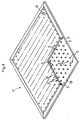
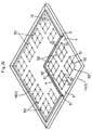
- a glass panel spacer relating to claim 12, as shown in Fig. 32, comprises a plurality of spacer bodies two-dimensionally interconnected to each other via a connecting member.
- these spacer bodies may be disposed at one time at the predetermined positions. So that, the disposing operation of the spacers may be carried out efficiently and consequently the production efficiency of the glass panel may be improved.
- a glass panel spacer relating to claim 13 is characterized in that the connecting member may be shrunk or eliminated by means of heating.
- the connecting member is shrunk by means of heating as this construction, the connecting member may be less conspicuous when the glass panel is completed, whereby the transparency of the glass panel may be improved.
- a glass panel spacer relating to claim 14 is characterized in that the connecting member may be dissolved by means of a solvent.
- the connecting member can be dissolved by means of a solvent, the connecting member may be removed entirely when the glass panel is completed, so that a glass panel having highest possible transparency may be obtained.
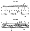
- the manufacturing method of this glass panel is a method of manufacturing a glass panel P comprised of two glass sheets as shown in Fig. 9 for example.
- the glass panel P shown in Fig. 9 includes two glass sheets, i.e. first glass sheet 1A and second glass sheet 1B, a plurality of spacers 5 interposed between the sheets for forming a space 4 therebetween, and outer peripheral edges 3 are sealed for assembling the two glass sheets 1A, 1B together.
- this glass panel P has a similar vertical section to that shown in Figs. 48 and 49 described hereinbefore in the description of the prior art, the spacers 5 thereof are fixed to the first glass sheet 1A.
- spacer-forming paste 11 capable of forming the spacers 5 is prepared in advanced.
- This paste 11 is obtained by mixing and kneading together glass frit formed of fine particles of low-melting glass having a lower fusing temperature than the softening point of the two glass sheets 1A, 1B with a binder made of an organic agent or the like (see Fig. 16).
- this paste 11 is heated up to the fusing temperature of the low-melting glass, the organic agent will be evaporated in association with the rise of the temperature and at the same time the fine particles of the low-melting glass are fused into glass to form pre-spacer forming elements 9.
- the glass will be crystallized subsequently, so that the softening point thereof too will be raised.
- the fusing temperature described above refers to such temperature as the low-melting glass becomes fluidized. Such fluidization generally occurs at a temperature where its viscosity becomes below 10 5 poise, which temperature is e.g. about 400 to 600°C in the case of common low-melting glass. Accordingly, when low-melting glass as sealing material S is heated and fused for sealing the outer peripheral edges 3 in the subsequent step of sealing these outer peripheral edges 3 of the glass panel P, there is no risk of the once-formed spacers 5 becoming softened or fluidized again in the course of the operation within the furnace.
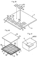
- the spacer-forming paste 11 is formed in a predetermined shape and disposed at predetermined positions on a spacer-disposing face 2A of the first glass sheet 1A which face will be located on the side adjacent the space 4 when the first glass sheet 1A is assembled into the glass panel P.
- a great number of paste-formed members 10 may be shaped in the predetermined size and disposed at one time at the predetermined positions.
- the paste-formed members 10 are to be vitrified through the baking process into pre-spacer forming elements 9.
- a screening plate having a thickness of 20 to 30 ⁇ m and defining a number of mimeographing holes 21 of 0.2 to 2.0 mm diameter in a grating pattern with a predetermined distance of about 20 mm is affixed to the spacer-disposing face 2A; then, the paste 11 will be rubbed onto the spacer-disposing face 2A through this screening plate 20.
- this screening plate 20 is removed from the spacer-disposing face 2A, the paste-formed members 10 having the predetermined size are formed on the spacer-disposing face 2A.
- the thickness of the screening plate 20, the diameter and disposing distance of the mimeographing holes 21 to be defined through this screening plate 20 will be appropriately determined, depending on e.g. the designing conditions of the glass panel P, such as the composition of the paste 11, the properties of the low-melting glass as the basic material.
- the baking process refers to heating the low-melting glass to a temperature higher than its fluidizing temperature to fuse the frit of the low-melting glass and then cooling it. When an ordinary low-melting glass is employed, it is heated to 400 to 600°C and then cooled.
- each spacer-forming paste 11 disposed as the paste-formed member 10 on the spacer-disposing face 2A of the glass sheet 1 is subjected to a predetermined solidifying operation, whereby a plurality of pre-spacer forming elements 9 are formed.
- the glass sheet retaining the paste-formed members 10 will be e.g. charged into a furnace maintained at the baking temperature of 400 to 600°C and this will be maintained inside the furnace until the plurality of paste-formed members 10 will be vitrified into the pre-spacer forming elements 9.
- each pre-spacer forming element 9 will be height-adjusted and shaped to obtain a predetermined height relative to the spacer-disposing face 2A, whereby the spacer 5 is formed.
- the temperature of the pre-spacer forming elements 9 fused to the glass sheet 1 taken out of the furnace is lowered by e.g. 40 to 70°C from the above-described baking temperature so as to maintain the softening temperature (e.g. 450°C) of the pre-spacer 5 forming elements at which the pre-spacer forming elements 9 are deformable; and under this condition, a roller 30 having fine knurled pattern on its surface will be moved along the spacer disposing face 2A with maintaining the surface of this roller at a predetermined distance (e.g. 20 ⁇ m) from the spacer-disposing face 2A, so as to press the contacting ends 6 of the pre-spacer forming elements 9 for shaping and adjusting them into the predetermined height, whereby the spacers 5 are formed.
- a predetermined distance e.g. 20 ⁇ m
- the height-adjusting shaping operation is effected is that the surface of the paste-formed member 10 formed by screen-printing of the paste 11 is not formed parallel to the spacer-disposing face 2A of the glass sheet 1. Rather, this surface of the paste-formed member 10 is formed e.g. with an upward projection as shown in Fig. 17. Therefore, if it is interposed as it is between the two glass sheets 1A, 1B, only the projecting portion will come into local contact with the face 2 of the second glass sheet 1B on the side of the space 4, so that there may occur such inconvenience as development of crack in the second glass sheet 1B.
- the surface having the knurled pattern of the roller 30 have surface roughness corresponding to the surface roughness of a coated abrasive No. 8000.
- this height-adjusting shaping operation of the pre-spacer forming elements 9 may be done by pressing of the paired glass sheets when the paired glass sheets are superposed and the sealing paste along the periphery thereof is baked.
- the second glass sheet 1B will be superposed with its face 2 on the side of the space 4 being oriented in opposition to the height-adjusted contacting ends 6 and then the glass sheets are assembled together, whereby the glass panel P is formed.
- the first glass sheet 1A will be superposed thereon with the spacers 5 being oriented downward, and then the paste 11 made of the low-melting glass as the sealing member S is disposed along the entire outer peripheral edges 3 thereof and this is then fused between the second glass sheet 1B and the outer peripheral edges 3 so as to seal therebetween.
- a communicating hole 13 (see Fig. 9) communicating with the space 4 may be provided, and an evacuating operation is effected through this communicating hole 13 to evacuate air from inside the space 4, then, the communicating hole 13 is sealed, whereby a vacuum glass panel P may be manufactured.
- the degree of vacuum inside the space be below 10 -2 torr. Incidentally, if this is further lowered below 10 -4 torr, the heat-insulating performance may be further improved.
- all of the paste-formed members 10 may be shaped at one time by the screen printing method and if theft baking operation is effected inside the furnace, the pre-spacer forming elements 9 may be disposed at one time on a plurality of glass sheets. And, if the sealing and assembling steps of the outer peripheral edge 3 after the superposing operation with the second glass sheet 1B too are effected inside a vacuum furnace, in this case too, a plurality of glass panels P may be manufactured. Hence, this method is suitable for mass production.
- each spacer 5 is fixed to the first glass sheet 1A and the other contacting end thereof is disposed to be movable relative to the second glass sheet 1B. Therefore, even if the panel, when used in a window pane, is warped due to e.g. wind pressure, the spacers 5 will be displaced relative to the second glass sheet 1B, whereby damage of the glass sheets 1 which would occur otherwise due to the provision of the spacers 5 may be avoided advantageously.
- the heat-transfer resistance at its border area may be increased, whereby the heat-insulating performance of the glass panel P may be improved.
- the spacer 5 according to this first embodiment may alternatively shaped as described next.
- a glass panel relating to the present invention may be alternatively constructed as follows.
- Fig. 26 shows a glass panel P, in which a plurality of spacers 5 are interposed between a pair of first glass sheet 1A and second glass sheet 1B having sheet faces thereof opposed to each other so as to form a space 4 between these glass sheets 1A, 1B and outer peripheral edges of the two glass sheets 1A, 1B are bonded together with a sealing material S made of e.g. low-melting glass so as to seal the space 4.
- a sealing material S made of e.g. low-melting glass
- the two glass sheets 1A, 1B are transparent float plate glass (720°C softening point) having thickness of about 3 mm.
- the glass sheet 1A is formed with slightly larger outer dimensions (306 mm x 306 mm) than the outer dimensions (300 mm x 300 mm) of the second glass sheet 1B so that when the sheet faces of the two glass sheets 1A, 1B are placed in opposition to each other the entire peripheral edges of the first glass sheet may form projecting portions 14 which project along the direction of sheet faces from the peripheral edges of the second glass sheet 1B.
- a through hole 13 for pressure reduction is formed in advance in either one of the first and second glass sheets 1A, 1B.
- This through hole 13 may be positioned where the sheets are bonded together with the sealing material S or may be elsewhere as well.
- the spacers 5 are disposed on the first glass sheet 1A.
- the methods of forming these spacers 5 are same as those described in the first embodiment.
- composition of the spacer-forming paste 11 employed in this second embodiment is shown in Table 1 below.
- the glass component contained in the spacer-forming paste 11 has a fusing temperature (the temperature at which the glass is fluidized, generally its viscosity becomes lower than 10 5 poise) of 590°C which is lower than the softening pint (720°C) of the glass sheets 1A, 1B and a softening point of 550°C which is higher than the fusing temperature (440 °C) of the sealing material S3.
- the composition of this glass component is shown in Table 2 below. Composition of Glass Component wt.% PbO 54 SiO 2 32 alkali 8 Al 2 O 3 3 TiO 2 3
- composition of the crystal particle powder component is shown in Table 3 below.
- the spacers 5 formed by the printing of the spacer-forming paste 11 are dried for a predetermined time period, they are subjected to a baking process in which the temperature inside the furnace is raised up to 590°C at the rate of 5°C per minute, they are then maintained for 30 minutes at this temperature, and then they are solidified by being cooled at the rate of 2 °C per minute, whereby the spacers 5 are formed as being fused on the glass sheet 1A.
- the paste 11 is to be subjected to a baking process to be described later to form the sealing material S. Its composition is shown in Table 4. Composition of Paste wt.% glass component 60 crystal particle powder component 3 resin component (ethyl cellulose) 0.2 oil 7
- the glass component contained in the paste 11 has a fusing temperature of 440°C.
- the composition of the paste 11 is shown in Table 5 below. Composition of Glass Component Contained in Paste wt.% PbO 80 B 2 O 3 12 SiO 2 0.1 ZnO 6 Al 2 O 3 2
- the paste 11 contains a glass component which has a lower lead content and a higher silicon content.
- composition of the crystal particle powder component is shown in Table 6 below.
- a baking operation is effected in which the temperature inside the heating furnace A is raised up to 450°C at the rate of 5°C per minute and kept at this temperature for 30 minutes and then is lowered at the rate of 2°C per minute.
- the peripheral edges of the first glass sheet 1A and the second glass sheet 1B are bonded together with the sealing material S and the space 4 is sealed.
- the air present in the space 4 is evacuated through the through hole 13, to achieve a pressure-reduced environment (below 1.0 x 10 -2 torr, more preferably, below 1.0 x 10 -4 torr), then, this through hole 13 is sealed.
- this sealing operation may be conducted under the pressure-reduced environment.
- the glass sheets 1A, 1B superposed each other across the spacers 5 therebetween will be heated under the pressure-reduced environment inside the vacuum furnace up to a temperature lower than the softening temperature of the glass component constituting the spacers 5. Then, after the paste 11 is fused, the temperature is lowered to the normal temperature, whereby the solidified sealing material S seals the space 4 under the pressure-reduced condition.
- the glass panel may be constructed alternatively as described below.
- a spacer 50 for use in a glass panel P relating to this embodiment, as shown in Figs. 32 and 33 is similar to those in the foregoing embodiment in that it is to be interposed between the first glass sheet 1A and the second glass sheet 1B having their sheet faces opposed to each other.
- this third embodiment employs such spacer 50 as shown in Figs. 34 through 36 for instance.
- This spacer 50 comprises a plurality of spacer bodies 51 interconnected in a two-dimensional form via connecting members 52. Of these, the each spacer body 51 is employed as a member for coming into contact with the first glass sheet 1A and the second glass sheet 1B for forming the space 4 therebetween.
- This spacer body 51 is formed of any material which is hardly deformed or collapsed when being bound between the first glass sheet 1A and the second glass sheet 1B and is capable of maintaining constant the distance between the first glass sheet 1A and the second glass sheet 1B.
- Its shape is not particularly limited. The shape may be e.g. spherical, cubic, rectangular, hollow cylindrical, solid cylindrical, or it may be any other complicated shape as well.
- this spacer body 51 will be appropriately set, depending on the distance to be secured between the first glass sheet 1A and the second glass sheet 1B.
- the material of this spacer body 51 it is preferred that the material have a required strength, high-temperature resistance, low heat-conductivity, good workability, etc.
- the material may be made of such metals or alloys thereof as nickel, molybdenum, tungsten, tantalum, titanium, aluminum, iron, steel, stainless steel, inconel or ceramics, minerals, carbon fibers, etc.
- the connecting member 52 is a member for two-dimensionally interconnecting the plurality of spacer bodies 51 together. And, this is used for connecting together a predetermined number of spacer bodies 51 to be disposed within a predetermined area on the glass sheet 1. By interconnecting the plurality of spacer bodies 51 in this manner, the plurality of spacer bodies 51 may be disposed at one time at the predetermined positions, whereby the disposing operation of the spacer 50 may be carried out efficiently.
- the connecting member 52 may be of various shapes. For instance, as shown in Figs. 34 through 36, it may be formed in the shape of line.
- a plurality of spacer bodies 51 are interconnected with each other as being distributed within the area having the predetermined planar shape or area. For instance, they are interconnected in rectangular, triangular or hexagonal pattern, as shown in Figs. 34 through 36, respectively.
- each spacer body 51 and the connecting member 52 may be realized in various ways.
- One way is to define a connecting hole 51a in the spacer body 5, into which hole one end of the connecting member 52 is inserted to be engaged or bonded thereto.
- Another way is to simply bond the end of the connecting member 52 with the spacer body 51, without modifying the spacer body 51 in particular.
- the spacer bodies 51 may be disposed over the entire face of the glass sheet 1 having any area and/or shape.
- the diameter of the connecting member 52 provided in the form of line is set smaller than the distance between the first glass sheet 1A and the second glass sheet 1B, so as to facilitate the evacuation of the air inside the space 4 when this space 4 is pressure-reduced.
- connecting member 52 is provided in the shape of line, this will reduce not only the amount of the material used in forming this connecting member 52, but also the weight of the spacer 50. Accordingly, there are achieved advantages in terms of economy or handling ease.
- the connecting members 52 may be left there after the spacer 50 is disposed. However, they may be removed also.
- the connecting member 52 may be made of such material as metals such as stainless steel, aluminum, or carbon fiber, etc. In this case, as the connecting member 52 is provided with a certain amount of rigidity, this will prevent disadvantageous irregularity in the mutual positioning of the spacers 5 interconnected with each other.
- connecting member 52 which is to be left may be made of any material which is shrunk due to heating or the like.
- connecting member 52 it is believed preferable that such connecting member 52 to be left be made in the form of line. For, if it is formed like line, the remaining connecting member 52 may be less conspicuous.
- this connecting member 52 should be made of any material which can be eliminated through combustion by heating e.g. the first glass sheet 1A or though evaporation or which can be dissolved by injection of various solvents into the space 4 prior to the heating of e.g. the first glass sheet 1A.
- the material which can be eliminated through combustion may be natural fibers, polymer-containing organic fibers, etc.
- the material which can be eliminated though evaporation may be such material which can be easily evaporated such as naphthalene, camphor, dry ice, or ice, etc.
- the material which can be eliminated though dissolution may be fibers of various synthetic resins, or water-solvent material such as soap, oblate, etc.
- the connecting member 52 may be provided in the form of thin strips as shown in Fig. 37 or in the form of sheet as shown in Fig. 38.
- this connecting member 52 may be utilized as an ornament of the glass panel P. If it is to be eliminated, the panel may be used as an ordinary glass panel P having transparency.
- this connecting member 52 For connecting this connecting member 52 with the spacer body 51, it is conceivable, for instance, to define a hole 52a in advance at a predetermined position of the connecting member 52 in the form of sheet and then to fit and bond the spacer body 51 at the hole 52a, or to dispose the spacer bodies 51 in advance at the predetermined positions and then to form the connecting member 52 in the form of a film so as to interconnect the respective spacer bodies 51.
- planar connecting member 52 may be formed of the same material as the linear connecting member 52 described above.
- the thickness of the connecting member 52 should be set smaller than the distance between the first glass sheet 1A and the second glass sheet 1B so as to facilitate the pressure-reducing operation of the inside of the space 4.
- the thinner the connecting member 52 the smaller amount of material may be used for forming the same, whereby it may be lighter-weight.
- the manufacturing method of the glass panel using this spacer 50 of the invention is substantially same as that of the foregoing embodiment.
- this third embodiment there will be described an example of the method of manufacturing the glass panel P under the atmospheric pressure environment, with reference to Figs. 39 through 41.
- the communicating hole 13 is sealed with a sealing glass material or the like. Thereafter, the glass panel P is taken out of the vacuum vessel 53, whereby the glass panel P is completed.
- the disposing operation of the spacer bodies 51 may be carried out very efficiently. As a result, the production efficiency of the glass panel P may be improved.
- the spacer 50 for the glass panel P of the invention is adapted to be shrinkable or removable by heating or be dissolvable by a solvent, a glass panel P having good transparency may be obtained.
- the glass panel P may be alternatively manufactured as follows.
- the glass panel according to the present invention may be used in a variety of applications. For instance, it may be used for building construction, vehicles (wind shied of an automobile, railway train, marine vessel) and machine components (a surface glass of a plasma display, a door or wall of a refrigerator or heat insulating device), etc.
Landscapes
- Engineering & Computer Science (AREA)
- Civil Engineering (AREA)
- Structural Engineering (AREA)
- Chemical & Material Sciences (AREA)
- Ceramic Engineering (AREA)
- Life Sciences & Earth Sciences (AREA)
- Chemical Kinetics & Catalysis (AREA)
- General Chemical & Material Sciences (AREA)
- Geochemistry & Mineralogy (AREA)
- Materials Engineering (AREA)
- Organic Chemistry (AREA)
- Joining Of Glass To Other Materials (AREA)
Applications Claiming Priority (7)
| Application Number | Priority Date | Filing Date | Title |
|---|---|---|---|
| JP12224898 | 1998-05-01 | ||
| JP10122248A JPH11314944A (ja) | 1998-05-01 | 1998-05-01 | ガラスパネルの製造方法 |
| JP13020998A JPH11322377A (ja) | 1998-05-13 | 1998-05-13 | ガラスパネル用間隔保持部材 |
| JP13020998 | 1998-05-13 | ||
| JP10262827A JP2000086304A (ja) | 1998-09-17 | 1998-09-17 | ガラスパネル |
| JP26282798 | 1998-09-17 | ||
| PCT/JP1999/002313 WO1999057074A1 (fr) | 1998-05-01 | 1999-04-28 | Panneau de verre, procede de fabrication et espaceur pour ce panneau de verre |
Publications (2)
| Publication Number | Publication Date |
|---|---|
| EP1004552A1 true EP1004552A1 (fr) | 2000-05-31 |
| EP1004552A4 EP1004552A4 (fr) | 2001-01-03 |
Family
ID=27314426
Family Applications (1)
| Application Number | Title | Priority Date | Filing Date |
|---|---|---|---|
| EP99918277A Withdrawn EP1004552A4 (fr) | 1998-05-01 | 1999-04-28 | Panneau de verre, procede de fabrication et espaceur pour ce panneau de verre |
Country Status (6)
| Country | Link |
|---|---|
| US (2) | US6387460B1 (fr) |
| EP (1) | EP1004552A4 (fr) |
| KR (1) | KR20010020595A (fr) |
| CN (1) | CN1266414A (fr) |
| CA (1) | CA2294858A1 (fr) |
| WO (1) | WO1999057074A1 (fr) |
Cited By (10)
| Publication number | Priority date | Publication date | Assignee | Title |
|---|---|---|---|---|
| WO2001061135A1 (fr) * | 2000-02-17 | 2001-08-23 | Guardian Industries Corporation | Verre d'isolation sous vide a elements d'espacement micronises |
| AU2002363814B2 (en) * | 2001-07-05 | 2008-01-03 | Nippon Sheet Glass Co., Ltd | Glass panel |
| WO2012163326A3 (fr) * | 2011-05-30 | 2013-03-28 | Grenzenbach Maschinenbau Gmbh | Verre isolant sous vide à solidité accrue et son procédé de fabrication |
| RU2525777C2 (ru) * | 2012-12-25 | 2014-08-20 | Таймасхан Амиралиевич Арсланов | Дополнительная теплосберегающая съемная накладка окна |
| EP3044398A4 (fr) * | 2013-09-13 | 2017-04-19 | 3M Innovative Properties Company | Films de distribution de plots pour vitrage sous vide et procédé s'appliquant à des unités de verre isolant |
| WO2017155779A1 (fr) * | 2016-03-07 | 2017-09-14 | 3M Innovative Properties Company | Espaceurs de vitrage sous vide pour vitrage isolant et vitrage isolant les comportant |
| WO2017155687A1 (fr) * | 2016-03-07 | 2017-09-14 | 3M Innovative Properties Company | Espaceurs de vitrage sous vide pour vitrage isolant et vitrage isolant les comportant |
| US20170268284A1 (en) * | 2014-08-21 | 2017-09-21 | Nippon Sheet Glass Company, Limited | Spacer member |
| EP3269690A4 (fr) * | 2015-03-13 | 2018-01-17 | Panasonic Intellectual Property Management Co., Ltd. | Procédé de fabrication d'un panneau de verre unitaire, procédé de fabrication d'une vitre, et dispositif de fabrication d'un substrat en verre avec élément espaceur |
| WO2020023233A1 (fr) | 2018-07-25 | 2020-01-30 | Kyun Jang Chin | Panneau de verre isolé sous vide comprenant une unité de colonne structurée |
Families Citing this family (35)
| Publication number | Priority date | Publication date | Assignee | Title |
|---|---|---|---|---|
| EP1144790A1 (fr) * | 1998-12-16 | 2001-10-17 | Bowmead Holding Inc. | Panneau de construction architectural |
| FR2807872B1 (fr) * | 2000-04-17 | 2002-08-30 | Saint Gobain Vitrage | Cadre en verre |
| US7114306B2 (en) * | 2000-06-14 | 2006-10-03 | Nippon Sheet Glass Co., Ltd. | Glass panel |
| JP2002167249A (ja) * | 2000-11-30 | 2002-06-11 | Nippon Sheet Glass Co Ltd | ガラスパネル |
| US6962834B2 (en) * | 2002-03-22 | 2005-11-08 | Stark David H | Wafer-level hermetic micro-device packages |
| US6627814B1 (en) * | 2002-03-22 | 2003-09-30 | David H. Stark | Hermetically sealed micro-device package with window |
| US7832177B2 (en) | 2002-03-22 | 2010-11-16 | Electronics Packaging Solutions, Inc. | Insulated glazing units |
| JP2004182567A (ja) * | 2002-12-05 | 2004-07-02 | Nippon Sheet Glass Co Ltd | 真空ガラスパネルの製造方法、及び該製造方法により製造された真空ガラスパネル |
| US20050217319A1 (en) * | 2002-12-05 | 2005-10-06 | Nippon Sheet Glass Company, Limited | Vacuum glass panel manufacturing method and vacuum glass panel manufactured by the manufacturing method |
| KR200415079Y1 (ko) * | 2006-02-01 | 2006-04-27 | 임주상 | 진공복층패널 |
| ITBO20070351A1 (it) * | 2007-05-11 | 2008-11-12 | Angelo Candiracci | Pannello per la realizzazione di una costruzione edile. |
| US7989040B2 (en) * | 2007-09-14 | 2011-08-02 | Electronics Packaging Solutions, Inc. | Insulating glass unit having multi-height internal standoffs and visible decoration |
| CN101462821A (zh) * | 2007-12-18 | 2009-06-24 | 欧阳宝武 | 平板轧凸真空玻璃 |
| EP2324183B1 (fr) | 2008-08-09 | 2014-06-25 | Eversealed Windows, Inc. | Joint d'étanchéité à bord souple asymétrique pour vitrage isolant vis-à-vis du vide |
| US8512830B2 (en) | 2009-01-15 | 2013-08-20 | Eversealed Windows, Inc. | Filament-strung stand-off elements for maintaining pane separation in vacuum insulating glazing units |
| WO2010083476A2 (fr) | 2009-01-15 | 2010-07-22 | Eversealed Windows, Inc | Joint de bordure souple pour unité de vitrage pour isolation sous vide |
| ITUD20090055A1 (it) * | 2009-03-10 | 2010-09-11 | Wasserstoff Ltd | Perfezionamento alla disposizione dei supporti all' interno delle vetrate con camera a vuoto (vig) per minimizzare le tensioni meccaniche interne delle lastre" |
| CN201377262Y (zh) * | 2009-04-10 | 2010-01-06 | 唐健正 | 真空平板玻璃支撑物 |
| KR101077484B1 (ko) * | 2010-03-17 | 2011-10-28 | 하호 | 일체형 하판 유리 및 그를 포함하는 진공 복층 유리의 제조 방법 |
| US8950162B2 (en) | 2010-06-02 | 2015-02-10 | Eversealed Windows, Inc. | Multi-pane glass unit having seal with adhesive and hermetic coating layer |
| WO2012047044A2 (fr) * | 2010-10-07 | 2012-04-12 | (주)엘지하우시스 | Panneau de verre à vide et procédé pour sa fabrication |
| US9328512B2 (en) | 2011-05-05 | 2016-05-03 | Eversealed Windows, Inc. | Method and apparatus for an insulating glazing unit and compliant seal for an insulating glazing unit |
| CN104136390B (zh) | 2012-03-07 | 2017-08-22 | 松下知识产权经营株式会社 | 多层玻璃 |
| US9428952B2 (en) * | 2012-05-31 | 2016-08-30 | Guardian Industries Corp. | Vacuum insulated glass (VIG) window unit with reduced seal height variation and method for making same |
| US9878954B2 (en) | 2013-09-13 | 2018-01-30 | 3M Innovative Properties Company | Vacuum glazing pillars for insulated glass units |
| US10165870B2 (en) | 2014-02-11 | 2019-01-01 | Anthony, Inc. | Display case door assembly with vacuum panel |
| US9498072B2 (en) | 2014-02-11 | 2016-11-22 | Anthony, Inc. | Display case door assembly with tempered glass vacuum panel |
| KR101578073B1 (ko) * | 2014-07-14 | 2015-12-16 | 코닝정밀소재 주식회사 | 기밀 밀봉 방법 및 기밀 밀봉된 기판 패키지 |
| US9366071B1 (en) * | 2014-12-03 | 2016-06-14 | Peter Petit | Low-friction spacer system for vacuum insulated glass |
| USD773690S1 (en) * | 2015-03-12 | 2016-12-06 | 3M Innovative Properties Company | Pillar for vacuum insulated glass unit |
| EP3268567A1 (fr) | 2015-03-12 | 2018-01-17 | 3M Innovative Properties Company | Plots de vitrage sous vide pour unités de verre isolant et unités de verre isolant les mettant en uvre |
| JP6464539B2 (ja) * | 2015-03-20 | 2019-02-06 | パナソニックIpマネジメント株式会社 | ガラスパネルユニット、ガラス窓、およびガラスパネルユニットの製造方法 |
| EP3438398B1 (fr) * | 2016-03-31 | 2021-05-05 | Panasonic Intellectual Property Management Co., Ltd. | Unité de panneau en verre et appareil la comprenant |
| US9687087B1 (en) | 2016-06-16 | 2017-06-27 | Anthony, Inc. | Display case door assembly with vacuum panel and lighting features |
| JP7383382B2 (ja) * | 2019-02-08 | 2023-11-20 | 日本板硝子株式会社 | ガラスユニット |
Citations (4)
| Publication number | Priority date | Publication date | Assignee | Title |
|---|---|---|---|---|
| FR2483564A1 (fr) * | 1980-06-03 | 1981-12-04 | Bourdel Jacques | Panneaux isolants sous vide |
| US5005557A (en) * | 1985-11-29 | 1991-04-09 | Baechli Emil | Heat-insulating building and/or light element |
| WO1994024398A1 (fr) * | 1990-09-27 | 1994-10-27 | Parker Kenneth R | Panneau d'isolation |
| FR2710681A1 (fr) * | 1993-09-27 | 1995-04-07 | Saint Gobain Vitrage Int | Vitrage isolant. |
Family Cites Families (3)
| Publication number | Priority date | Publication date | Assignee | Title |
|---|---|---|---|---|
| JPS50156525A (fr) * | 1974-06-10 | 1975-12-17 | ||
| JPH0617579A (ja) * | 1992-04-06 | 1994-01-25 | Kazuo Kuroiwa | 真空断熱ガラス板及びその製造方法 |
| DK0645516T3 (da) * | 1993-09-27 | 2002-05-13 | Saint Gobain | Fremgangsmåde til frembringelse af vakuum i en isoleringsrude samt en isoleringsrude |
-
1999
- 1999-04-28 US US09/445,839 patent/US6387460B1/en not_active Expired - Fee Related
- 1999-04-28 WO PCT/JP1999/002313 patent/WO1999057074A1/fr active IP Right Grant
- 1999-04-28 EP EP99918277A patent/EP1004552A4/fr not_active Withdrawn
- 1999-04-28 KR KR1019997012577A patent/KR20010020595A/ko active IP Right Grant
- 1999-04-28 CA CA002294858A patent/CA2294858A1/fr not_active Abandoned
- 1999-04-28 CN CN99800659A patent/CN1266414A/zh active Pending
-
2002
- 2002-02-11 US US10/073,752 patent/US20020110653A1/en not_active Abandoned
Patent Citations (4)
| Publication number | Priority date | Publication date | Assignee | Title |
|---|---|---|---|---|
| FR2483564A1 (fr) * | 1980-06-03 | 1981-12-04 | Bourdel Jacques | Panneaux isolants sous vide |
| US5005557A (en) * | 1985-11-29 | 1991-04-09 | Baechli Emil | Heat-insulating building and/or light element |
| WO1994024398A1 (fr) * | 1990-09-27 | 1994-10-27 | Parker Kenneth R | Panneau d'isolation |
| FR2710681A1 (fr) * | 1993-09-27 | 1995-04-07 | Saint Gobain Vitrage Int | Vitrage isolant. |
Non-Patent Citations (1)
| Title |
|---|
| See also references of WO9957074A1 * |
Cited By (16)
| Publication number | Priority date | Publication date | Assignee | Title |
|---|---|---|---|---|
| WO2001061135A1 (fr) * | 2000-02-17 | 2001-08-23 | Guardian Industries Corporation | Verre d'isolation sous vide a elements d'espacement micronises |
| AU2002363814B2 (en) * | 2001-07-05 | 2008-01-03 | Nippon Sheet Glass Co., Ltd | Glass panel |
| WO2012163326A3 (fr) * | 2011-05-30 | 2013-03-28 | Grenzenbach Maschinenbau Gmbh | Verre isolant sous vide à solidité accrue et son procédé de fabrication |
| US9551178B2 (en) | 2011-05-30 | 2017-01-24 | Grenzebach Maschinenbau Gmbh | Vacuum insulated glass having increased stability and method for the production thereof |
| RU2525777C2 (ru) * | 2012-12-25 | 2014-08-20 | Таймасхан Амиралиевич Арсланов | Дополнительная теплосберегающая съемная накладка окна |
| US10253551B2 (en) | 2013-09-13 | 2019-04-09 | 3M Innovative Properties Company | Methods of transferring pillars from pillar delivery films |
| US9790732B2 (en) | 2013-09-13 | 2017-10-17 | 3M Innovative Properties Company | Methods of transferring pillars from pillar delivery films |
| EP3044398A4 (fr) * | 2013-09-13 | 2017-04-19 | 3M Innovative Properties Company | Films de distribution de plots pour vitrage sous vide et procédé s'appliquant à des unités de verre isolant |
| US20170268284A1 (en) * | 2014-08-21 | 2017-09-21 | Nippon Sheet Glass Company, Limited | Spacer member |
| EP3184498A4 (fr) * | 2014-08-21 | 2018-04-04 | Nippon Sheet Glass Company, Limited | Élément d'entretoise |
| EP3269690A4 (fr) * | 2015-03-13 | 2018-01-17 | Panasonic Intellectual Property Management Co., Ltd. | Procédé de fabrication d'un panneau de verre unitaire, procédé de fabrication d'une vitre, et dispositif de fabrication d'un substrat en verre avec élément espaceur |
| WO2017155779A1 (fr) * | 2016-03-07 | 2017-09-14 | 3M Innovative Properties Company | Espaceurs de vitrage sous vide pour vitrage isolant et vitrage isolant les comportant |
| WO2017155687A1 (fr) * | 2016-03-07 | 2017-09-14 | 3M Innovative Properties Company | Espaceurs de vitrage sous vide pour vitrage isolant et vitrage isolant les comportant |
| WO2020023233A1 (fr) | 2018-07-25 | 2020-01-30 | Kyun Jang Chin | Panneau de verre isolé sous vide comprenant une unité de colonne structurée |
| EP3749516A4 (fr) * | 2018-07-25 | 2021-06-09 | Kyun Jang Chin | Panneau de verre isolé sous vide comprenant une unité de colonne structurée |
| JP2021526119A (ja) * | 2018-07-25 | 2021-09-30 | チン、ギュン ジャンCHIN, Kyun Jang | 真空断熱ガラスパネル |
Also Published As
| Publication number | Publication date |
|---|---|
| US6387460B1 (en) | 2002-05-14 |
| KR20010020595A (ko) | 2001-03-15 |
| CA2294858A1 (fr) | 1999-11-11 |
| US20020110653A1 (en) | 2002-08-15 |
| CN1266414A (zh) | 2000-09-13 |
| WO1999057074A1 (fr) | 1999-11-11 |
| EP1004552A4 (fr) | 2001-01-03 |
Similar Documents
| Publication | Publication Date | Title |
|---|---|---|
| US6387460B1 (en) | Glass panel | |
| US6479112B1 (en) | Glass panel and method of manufacturing thereof and spacers used for glass panel | |
| US6641689B1 (en) | Vacuum IG window unit with peripheral seal at least partially diffused at temper | |
| KR101172245B1 (ko) | 유리 리본 사출용 로울러 및 판유리 제조 방법 | |
| US4969966A (en) | Method of producing curved laminated glass panels | |
| EP2653454A1 (fr) | Panneau de verre sous vide et procédé de fabrication de celui-ci | |
| WO2013172033A1 (fr) | Procédé de fabrication de double vitrage | |
| CA2201897A1 (fr) | Ameliorations apportees a la conception de vitrages sous vide | |
| JP2013540684A (ja) | 真空ガラスパネル及びその製造方法 | |
| EP0603830A2 (fr) | Composition colorante céramique et procédé de formation d'une couche colorante céramique sur une plaque de verre l'utilisant | |
| KR101071879B1 (ko) | 스페이서를 포함하는 단열용 진공 유리 패널 및 그 제조 방법 | |
| WO2000000705A1 (fr) | Corps creux dans lequel a ete fait le vide, destine a l'isolation thermique | |
| KR100461089B1 (ko) | 유리 패널 | |
| JP2016030718A (ja) | 真空複層ガラスの製造方法、および真空複層ガラスの製造装置 | |
| US20210348439A1 (en) | Pump out tube preform | |
| KR100202332B1 (ko) | 진공창의 밀봉방법 및 그 제품 | |
| KR101916244B1 (ko) | 자동차에 적용되는 3d 커브드 글라스 제조 방법 | |
| JPH09259754A (ja) | プラズマディスプレイパネル用基板及びそれを用いたプラズマディスプレイパネルの製造方法 | |
| JP2008266059A (ja) | 減圧複層ガラスパネル | |
| CN115213430A (zh) | 一种3d打印粉材成型的温场空格缓渗装置及其应用 | |
| CN207526343U (zh) | 中空玻璃 | |
| JP2000086304A (ja) | ガラスパネル | |
| EP1681701A2 (fr) | Méthode de fixation pour un tube de ventilation d'un panneau d'affichage | |
| JP2000220357A (ja) | 低圧複層ガラスおよびその製造方法 |
Legal Events
| Date | Code | Title | Description |
|---|---|---|---|
| PUAI | Public reference made under article 153(3) epc to a published international application that has entered the european phase |
Free format text: ORIGINAL CODE: 0009012 |
|
| AK | Designated contracting states |
Kind code of ref document: A1 Designated state(s): DE DK FR GB |
|
| 17P | Request for examination filed |
Effective date: 20000428 |
|
| A4 | Supplementary search report drawn up and despatched |
Effective date: 20001122 |
|
| AK | Designated contracting states |
Kind code of ref document: A4 Designated state(s): DE DK FR GB |
|
| 17Q | First examination report despatched |
Effective date: 20030205 |
|
| GRAP | Despatch of communication of intention to grant a patent |
Free format text: ORIGINAL CODE: EPIDOSNIGR1 |
|
| STAA | Information on the status of an ep patent application or granted ep patent |
Free format text: STATUS: THE APPLICATION IS DEEMED TO BE WITHDRAWN |
|
| 18D | Application deemed to be withdrawn |
Effective date: 20051101 |