EP1004392B1 - Schwenktisch einer Werkzeugmaschine - Google Patents
Schwenktisch einer Werkzeugmaschine Download PDFInfo
- Publication number
- EP1004392B1 EP1004392B1 EP99122844A EP99122844A EP1004392B1 EP 1004392 B1 EP1004392 B1 EP 1004392B1 EP 99122844 A EP99122844 A EP 99122844A EP 99122844 A EP99122844 A EP 99122844A EP 1004392 B1 EP1004392 B1 EP 1004392B1
- Authority
- EP
- European Patent Office
- Prior art keywords
- base frame
- frame
- clamping plate
- hydraulic cylinders
- parallel
- Prior art date
- Legal status (The legal status is an assumption and is not a legal conclusion. Google has not performed a legal analysis and makes no representation as to the accuracy of the status listed.)
- Expired - Lifetime
Links
- 230000013011 mating Effects 0.000 claims description 2
- 239000011093 chipboard Substances 0.000 description 1
- 230000003750 conditioning effect Effects 0.000 description 1
- 238000003754 machining Methods 0.000 description 1
- 125000006850 spacer group Chemical group 0.000 description 1
Images


Classifications
-
- B—PERFORMING OPERATIONS; TRANSPORTING
- B23—MACHINE TOOLS; METAL-WORKING NOT OTHERWISE PROVIDED FOR
- B23Q—DETAILS, COMPONENTS, OR ACCESSORIES FOR MACHINE TOOLS, e.g. ARRANGEMENTS FOR COPYING OR CONTROLLING; MACHINE TOOLS IN GENERAL CHARACTERISED BY THE CONSTRUCTION OF PARTICULAR DETAILS OR COMPONENTS; COMBINATIONS OR ASSOCIATIONS OF METAL-WORKING MACHINES, NOT DIRECTED TO A PARTICULAR RESULT
- B23Q1/00—Members which are comprised in the general build-up of a form of machine, particularly relatively large fixed members
- B23Q1/25—Movable or adjustable work or tool supports
- B23Q1/26—Movable or adjustable work or tool supports characterised by constructional features relating to the co-operation of relatively movable members; Means for preventing relative movement of such members
- B23Q1/28—Means for securing sliding members in any desired position
-
- B—PERFORMING OPERATIONS; TRANSPORTING
- B23—MACHINE TOOLS; METAL-WORKING NOT OTHERWISE PROVIDED FOR
- B23Q—DETAILS, COMPONENTS, OR ACCESSORIES FOR MACHINE TOOLS, e.g. ARRANGEMENTS FOR COPYING OR CONTROLLING; MACHINE TOOLS IN GENERAL CHARACTERISED BY THE CONSTRUCTION OF PARTICULAR DETAILS OR COMPONENTS; COMBINATIONS OR ASSOCIATIONS OF METAL-WORKING MACHINES, NOT DIRECTED TO A PARTICULAR RESULT
- B23Q1/00—Members which are comprised in the general build-up of a form of machine, particularly relatively large fixed members
- B23Q1/25—Movable or adjustable work or tool supports
- B23Q1/44—Movable or adjustable work or tool supports using particular mechanisms
- B23Q1/50—Movable or adjustable work or tool supports using particular mechanisms with rotating pairs only, the rotating pairs being the first two elements of the mechanism
- B23Q1/52—Movable or adjustable work or tool supports using particular mechanisms with rotating pairs only, the rotating pairs being the first two elements of the mechanism a single rotating pair
Definitions
- the invention relates to a swivel table of a machine tool, consisting of a base frame with a clamping plate on the side Rib part is pivotally arranged, the pivot unit below the clamping plate is arranged.
- DE 2813 656 includes a swivel table of a machine tool a pivot axis lying parallel to the clamping plate is known.
- the Swiveling movement is effected by a swiveling device, which in a base frame is arranged below the clamping plate, the clamping plate being articulated on one side of the base frame by means of bearing bolts.
- This Swivel table is used to machine a workpiece that is in horizontal position is clamped on the clamping plate and in one more or less pivoted position to be processed.
- DE 4012 999 C2 shows a swivel table with adjustable Inclination for a machine tool.
- This swivel table can do that represent the actual work table of a machine tool, or he can be adjusted to an existing incline that is not adjustable Work table of a machine tool can be placed.
- the inclination of the table can be adjusted using cams.
- the difference in height of the table inclination is determined by the smallest and largest diameter of the cam limited.
- a spacer is arranged on the work table, the can be inserted between the cam and the adjacent table part.
- the object of the invention is a swivel table Machine tool consisting of a base frame on the side a clamping plate with a rib part is pivoted, the Swivel device is arranged below the clamping plate develop large workpieces, for example five tons, for processing on the clamping plate at high Repeatability in a horizontal and a vertical position can pivot.
- the object is achieved in that the clamping plate is hinged to one side of the base frame by means of bearing bolts that in the base frame, a geared motor is attached, the motor shaft, the is arranged parallel to the swivel axis, with a pinion on each side is provided, each of the pinions with one on the rib part of the Clamping plate attached gear segment is in operative connection, parallel opposite of the two gear segments on at the other end each a bracket on a counter surface on the rib part of the Clamping plate is attached, one for each of the brackets in the base frame There is a recess on the base frame for the support block Mating surface is attached so that each gear segment on the whole Has circumference a wreath, in the base frame pairs of plant jaws are arranged behind the rim of the gear segments extend and movable but captive pressure pieces in the form of Circular sections, the pressure pieces of the pair of plant jaws with both rings of the gear segments are operatively connected, wherein in the base frame two hydraulic cylinders
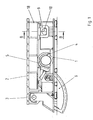
- a clamping plate 2 with rib part 18 can assume two fixed positions, a horizontal one in FIG. 1 and a vertical one in FIG. 3, a high level of repeatability being achieved by an appropriate locking and the machining forces being absorbed.
- Figure 1 shows a base frame 1 in which a geared motor 4 with two pinions 5 is arranged.
- the pinions 5 act together with two gear segments 6, which are firmly connected to a rib part 18 of a clamping plate 2.
- the clamping plate 2 is brought from the horizontal into the vertical position and back via the gear segments 6.
- two support blocks 7 are fastened to the base frame 1, on which the clamping plate 2 rests with its rib part 18 and a counter surface 8 attached to it.
- each of the gear segments 6 On the counter surface 8 there are opposite each of the gear segments 6 a bracket 9 which engage in corresponding recesses 17 of the base frame 1.
- Wedges 10, which are moved by hydraulic cylinders 11, are operatively connected to the holding brackets 9.
- the wedges 10 have a cylindrical back and thus get good contact with the correspondingly inclined counter surface on the holding bracket 9 with their wedge surface. If the clamping plate 2 is to be brought from the horizontal into the vertical position, the wedges 10 are pulled back into the base frame 1 by the hydraulic cylinders 11 until the clamping plate 2 with the holding brackets 9 can move freely upwards.
- the locking of the clamping plate 2 in the vertical position is shown in FIGS. 3 and 4.
- the gear segment 6 is widened in a ring shape on the entire circumference.
- pairs of contact jaws 12 are fastened, which extend behind the rim 13 of the gear segments 6.
- the contact jaws 12 carry movable but captive pressure pieces 14 in the form of circular sections, as shown in FIG. 3.
- the pressure pieces 14 compensate for angle differences due to their cylindrical back. They come to rest on corresponding counter surfaces on the rim 13 of the gear segments 6.
- the gear segments 6 are on the rim 13 the outer surface is inclined accordingly. Through the cylindrical back, the wedges 15 get good contact to the respective counter surface on the rings 13.
Landscapes
- Engineering & Computer Science (AREA)
- Mechanical Engineering (AREA)
- Machine Tool Units (AREA)
- Jigs For Machine Tools (AREA)
- Turning (AREA)
Description
- Figur 1:
- eine schematische Darstellung eines Schwenktisches in waagerechter Lage als Seitenansicht,
- Figur 2:
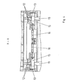
- Schnitt B-B nach Figur 1,
- Figur 3:
- den Schwenktisch nach Figur 1 in senkrechter Lage und
- Figur 4:
- Schnitt A-A nach Figur 3.
Soll die Spannplatte 2 aus der waagerechten in die senkrechte Position gebracht werden, werden die Keile 10 durch die Hydraulikzylinder 11 so weit in das Grundgestell 1 zurückgezogen, bis sich die Spannplatte 2 mit den Haltebügeln 9 frei nach oben bewegen kann. Die Arretierung der Spannplatte 2 in der senkrechten Stellung zeigen Figur 3 und 4. Das Zahnradsegment 6 ist am gesamten Umfang kranzförmig verbreitert. Im Grundgestell 1 sind Paare von Anlagebacken 12 befestigt, die sich bis hinter den Kranz 13 der Zahnradsegmente 6 erstrecken. Die Anlagebacken 12 tragen bewegliche, aber unverlierbare Druckstücke 14 in Form von Kreisabschnitten, wie Figur 3 zeigt. Die Druckstücke 14 gleichen durch ihren zylindrischen Rücken Winkeldifferenzen aus. Sie kommen zur Anlage an entsprechenden Gegenflächen am Kranz 13 der Zahnradsegmente 6. Gegenüber von den Anlagebacken 12 mit den Druckstücken 14 befinden sich zwei weitere Keile 15 mit zylindrischem Rücken, bewegt von zwei weiteren Hydraulikzylindern 16 im Grundgestell 1. Am Kranz 13 der Zahnradsegmente 6 ist die Außenfläche entsprechend geneigt. Durch den zylindrischen Rücken bekommen die Keile 15 einen guten Kontakt zur jeweiligen Gegenfläche an den Kränzen 13. Soll die Spannplatte 2 zurück in die waagerechte Stellung gebracht werden, müssen die Keile 15 mit Hydraulikzylinder 16 soweit zurückgezogen werden, daß die Kränze 13 vorbei bewegt werden können. Dabei taucht ein Teil der Zahnradsegmente 6 in einen Durchlaß 19 des Maschinenfundamentes ein.
- 1 =
- Grundgestell
- 2 =
- Spannplatte
- 3 =
- Lagerbolzen
- 4 =
- Getriebemotor
- 5 =
- Ritzel
- 6 =
- Zahnradsegment
- 7 =
- Auflageklotz
- 8 =
- Gegenfläche
- 9 =
- Haltebügel
- 10 =
- Keil
- 11 =
- Hydraulikzylinder
- 12 =
- Anlagebacken
- 13 =
- Kranz
- 14 =
- Druckstück
- 15 =
- Keil
- 16 =
- Hydraulikzylinder
- 17 =
- Ausnehmung
- 18 =
- Rippenteil
- 19 =
- Durchlaß
Claims (1)
- Schwenktisch einer Werkzeugmaschine, bestehend aus einem Grundgestell (1) auf dem seitlich eine Spannplatte (2) mit Rippenteil (18) schwenkbar angelenkt ist, deren Schwenkeinrichtung unterhalb der Spannplatte (2) angeordnet ist, wobei die Spannplatte (2) mittels Lagerbolzen (3) an einer Seite des Grundgestelles (1) angelenkt ist, dadurch gekennzeichnet, daß im Grundgestell (1) ein Getriebemotor (4) befestigt ist, dessen Motorwelle, die parallel zur Schwenkachse angeordnet ist, beidseitig mit je einem Ritzel (5) versehen ist, jedes der Ritzel (5) mit je einem am Rippenteil (18) der Spannplatte (2) befestigten Zahnradsegment (6) in Wirkverbindung steht, parallel gegenüberliegend von den beiden Zahnradsegmenten (6) am anderen Ende je ein Haltebügel (9) an einer Gegenfläche (8) am Rippenteil (18) der Spannplatte (2) befestigt ist, für jeden der Haltebügel (9) im Grundgestell (1) eine Ausnehmung (17) vorhanden ist, am Grundgestell (1) ein Auflageklotz (7) für die Gegenfläche (8) befestigt ist, daß jedes Zahnradsegment (6) am gesamten Umfang einen Kranz (13) aufweist, im Grundgestell (1) Paare von Anlagebacken (12) angeordnet sind, die sich hinter den Kranz (13) der Zahnradsegmente (6) erstrecken und bewegliche, aber unverlierbare Druckstücke (14) in Form von Kreisabschnitten, die Druckstücke (14) der paarigen Anlagebacken (12) mit beiden Kränzen (13) der Zahnradsegmente (6) in Wirkverbindung stehen, wobei im Grundgestell (1) zwei Hydraulikzylinder (11) angeordnet sind, die parallel zur Getriebemotorachsrichtung je einen Keil (10) mit zylindrischem Rücken zwischen Grundgestell (1) und Kranz (13), der eine entsprechend geneigte Außenfläche aufweist, bewegen, und, daß zwei weitere Hydraulikzylinder (16) im Grundgestell (1) parallel zu den Hydraulikzylindern (11) angeordnet sind, die je einen Keil (15) mit zylindrischem Rücken zwischen Grundgestell (1) und in den in die Ausnehmungen (17) des Grundgestelles (1) eingefahrenen Haltebügeln (9), die entsprechend geneigte Flächen aufweisen, bewegen.
Applications Claiming Priority (2)
| Application Number | Priority Date | Filing Date | Title |
|---|---|---|---|
| DE19854745 | 1998-11-27 | ||
| DE19854745A DE19854745A1 (de) | 1998-11-27 | 1998-11-27 | Schwenktisch einer Werkzeugmaschine |
Publications (3)
| Publication Number | Publication Date |
|---|---|
| EP1004392A2 EP1004392A2 (de) | 2000-05-31 |
| EP1004392A3 EP1004392A3 (de) | 2001-09-12 |
| EP1004392B1 true EP1004392B1 (de) | 2004-04-07 |
Family
ID=7889206
Family Applications (1)
| Application Number | Title | Priority Date | Filing Date |
|---|---|---|---|
| EP99122844A Expired - Lifetime EP1004392B1 (de) | 1998-11-27 | 1999-11-17 | Schwenktisch einer Werkzeugmaschine |
Country Status (3)
| Country | Link |
|---|---|
| EP (1) | EP1004392B1 (de) |
| AT (1) | ATE263654T1 (de) |
| DE (2) | DE19854745A1 (de) |
Families Citing this family (5)
| Publication number | Priority date | Publication date | Assignee | Title |
|---|---|---|---|---|
| ITBO20040375A1 (it) * | 2004-06-14 | 2004-09-14 | Jobs Spa | Unita' porta pezzo per macchine utensili |
| DE102006005254A1 (de) * | 2006-02-02 | 2007-08-09 | Otto Martin Maschinenbau Gmbh & Co. Kg | Bearbeitungsmaschine mit einem schwenkbaren Bearbeitungswerkzeug |
| DE102006045321B4 (de) * | 2006-09-22 | 2011-06-30 | Otto Martin Maschinenbau GmbH & Co. KG, 87724 | Bearbeitungsmaschine und Verfahren für das Positionieren eines schwenkbaren Bearbeitungswerkzeuges |
| CN102407448B (zh) * | 2011-09-30 | 2013-05-22 | 齐齐哈尔二机床(集团)有限责任公司 | 具有回转功能的滑枕镗铣头 |
| CN104057311A (zh) * | 2014-06-30 | 2014-09-24 | 滁州开关电器科技有限公司 | 一种用于机床万向头的支承辊 |
Family Cites Families (2)
| Publication number | Priority date | Publication date | Assignee | Title |
|---|---|---|---|---|
| FR2530989A1 (fr) * | 1982-07-29 | 1984-02-03 | Framatome Sa | Dispositif de basculement de pieces de grande dimension |
| JP2721237B2 (ja) * | 1989-04-27 | 1998-03-04 | 株式会社東芝 | 熱交換器水室鏡の位置決め装置 |
-
1998
- 1998-11-27 DE DE19854745A patent/DE19854745A1/de not_active Withdrawn
-
1999
- 1999-11-17 DE DE59909103T patent/DE59909103D1/de not_active Expired - Lifetime
- 1999-11-17 EP EP99122844A patent/EP1004392B1/de not_active Expired - Lifetime
- 1999-11-17 AT AT99122844T patent/ATE263654T1/de not_active IP Right Cessation
Also Published As
| Publication number | Publication date |
|---|---|
| DE19854745A1 (de) | 2000-05-31 |
| ATE263654T1 (de) | 2004-04-15 |
| DE59909103D1 (de) | 2004-05-13 |
| EP1004392A3 (de) | 2001-09-12 |
| EP1004392A2 (de) | 2000-05-31 |
Similar Documents
| Publication | Publication Date | Title |
|---|---|---|
| DE3534428C2 (de) | ||
| EP0218991B1 (de) | Zentrier- und Einspannvorrichtung für längliche Rundkörper unterschiedlicher Durchmesser | |
| DE602005005575T2 (de) | Biegeform mit einem Schraubstock zum Einspannen eines länglichen Elementes in einer Biegemaschine | |
| EP3475008B1 (de) | Vorrichtung zum kalibrieren und richten von hohlen bauteilen sowie verfahren mit einer derartigen vorrichtung | |
| EP0649687B1 (de) | Rohrbiegemaschine | |
| EP0623421A1 (de) | Vorrichtung zum endseitigen Ausformen von rohrförmigen Werkstücken mit unterschiedlichen Durchmessern | |
| DE69832426T2 (de) | Pressvorrichtung für Metallblech | |
| DE3407363A1 (de) | Vorrichtung zum durchfuehren von biegeversuchen | |
| EP0467383A1 (de) | Schleifgerät | |
| DE2455596C3 (de) | Presse mit Konvex- und Konkavwerkzeug zum Anbiegen der Ränder von Blechen | |
| DE19854745A1 (de) | Schwenktisch einer Werkzeugmaschine | |
| DE19508864C1 (de) | Maschine zum Ummanteln von länglichen Werkstücken | |
| EP0118739A2 (de) | Rohrbiegeanlage | |
| EP0076783B1 (de) | Biegemaschine für Rohre und Profilschienen | |
| DE1502561B1 (de) | Vorrichtung zum Spannen von zu beschleifenden rohrfoermigen Werkstuecken aus Glas u.dgl. | |
| DE3048738C2 (de) | Vorschubeinrichtung zum intermittierenden Drehen eines Kreissägeblattes | |
| EP0802036A2 (de) | Vorrichtung zum Stumpfschweissen von thermoplastischen Kunststoffrohren | |
| EP0544871A1 (de) | Maschine zum mehrstufigen bearbeiten von kreissägeblättern. | |
| DE2201791C3 (de) | Einspann- und Richtvorrichtung für aus Blechen gepreßte, vorzugsweise konische, schlitzrohrartige Masten o.dgl. bei einer Rohrschweißvorrichtung | |
| DE186709C (de) | ||
| DE10031460B4 (de) | Aufspann-und Positioniervorrichtung, insbesondere für lange und dünne Werkstücke | |
| DE29819851U1 (de) | Seil-Blocksäge für die Bearbeitung von Natur- und Kunststeinblöcken | |
| EP0534190B1 (de) | Schleifmaschine für die Enden keramischer Henkel | |
| CH628536A5 (en) | Sheet rounding machine with at least one abutment for arching sheet-metal blanks in the form of annular segments to give conical parts | |
| DE2417410C2 (de) | Schleifmaschine zum Bearbeiten von hohlzylindrischenWerkstücken mit von der Kreisform abweichendem Querschnitt |
Legal Events
| Date | Code | Title | Description |
|---|---|---|---|
| PUAI | Public reference made under article 153(3) epc to a published international application that has entered the european phase |
Free format text: ORIGINAL CODE: 0009012 |
|
| 17P | Request for examination filed |
Effective date: 19991117 |
|
| AK | Designated contracting states |
Kind code of ref document: A2 Designated state(s): AT BE CH CY DE DK ES FI FR GB GR IE IT LI LU MC NL PT SE |
|
| AX | Request for extension of the european patent |
Free format text: AL;LT;LV;MK;RO;SI |
|
| PUAL | Search report despatched |
Free format text: ORIGINAL CODE: 0009013 |
|
| AK | Designated contracting states |
Kind code of ref document: A3 Designated state(s): AT BE CH CY DE DK ES FI FR GB GR IE IT LI LU MC NL PT SE |
|
| AX | Request for extension of the european patent |
Free format text: AL;LT;LV;MK;RO;SI |
|
| AKX | Designation fees paid |
Free format text: AT BE CH CY DE DK ES FI FR GB GR IE IT LI LU MC NL PT SE |
|
| GRAP | Despatch of communication of intention to grant a patent |
Free format text: ORIGINAL CODE: EPIDOSNIGR1 |
|
| GRAS | Grant fee paid |
Free format text: ORIGINAL CODE: EPIDOSNIGR3 |
|
| GRAA | (expected) grant |
Free format text: ORIGINAL CODE: 0009210 |
|
| AK | Designated contracting states |
Kind code of ref document: B1 Designated state(s): AT BE CH CY DE DK ES FI FR GB GR IE IT LI LU MC NL PT SE |
|
| PG25 | Lapsed in a contracting state [announced via postgrant information from national office to epo] |
Ref country code: NL Free format text: LAPSE BECAUSE OF FAILURE TO SUBMIT A TRANSLATION OF THE DESCRIPTION OR TO PAY THE FEE WITHIN THE PRESCRIBED TIME-LIMIT Effective date: 20040407 Ref country code: IT Free format text: LAPSE BECAUSE OF FAILURE TO SUBMIT A TRANSLATION OF THE DESCRIPTION OR TO PAY THE FEE WITHIN THE PRE;WARNING: LAPSES OF ITALIAN PATENTS WITH EFFECTIVE DATE BEFORE 2007 MAY HAVE OCCURRED AT ANY TIME BEFORE 2007. THE CORRECT EFFECTIVE DATE MAY BE DIFFERENT FROM THE ONE RECORDED.SCRIBED TIME-LIMIT Effective date: 20040407 Ref country code: IE Free format text: LAPSE BECAUSE OF FAILURE TO SUBMIT A TRANSLATION OF THE DESCRIPTION OR TO PAY THE FEE WITHIN THE PRESCRIBED TIME-LIMIT Effective date: 20040407 Ref country code: GB Free format text: LAPSE BECAUSE OF FAILURE TO SUBMIT A TRANSLATION OF THE DESCRIPTION OR TO PAY THE FEE WITHIN THE PRESCRIBED TIME-LIMIT Effective date: 20040407 Ref country code: FR Free format text: LAPSE BECAUSE OF FAILURE TO SUBMIT A TRANSLATION OF THE DESCRIPTION OR TO PAY THE FEE WITHIN THE PRESCRIBED TIME-LIMIT Effective date: 20040407 Ref country code: FI Free format text: LAPSE BECAUSE OF FAILURE TO SUBMIT A TRANSLATION OF THE DESCRIPTION OR TO PAY THE FEE WITHIN THE PRESCRIBED TIME-LIMIT Effective date: 20040407 Ref country code: ES Free format text: LAPSE BECAUSE OF FAILURE TO SUBMIT A TRANSLATION OF THE DESCRIPTION OR TO PAY THE FEE WITHIN THE PRESCRIBED TIME-LIMIT Effective date: 20040407 Ref country code: CY Free format text: LAPSE BECAUSE OF FAILURE TO SUBMIT A TRANSLATION OF THE DESCRIPTION OR TO PAY THE FEE WITHIN THE PRESCRIBED TIME-LIMIT Effective date: 20040407 |
|
| REG | Reference to a national code |
Ref country code: GB Ref legal event code: FG4D Free format text: NOT ENGLISH |
|
| REG | Reference to a national code |
Ref country code: CH Ref legal event code: EP |
|
| REF | Corresponds to: |
Ref document number: 59909103 Country of ref document: DE Date of ref document: 20040513 Kind code of ref document: P |
|
| REG | Reference to a national code |
Ref country code: IE Ref legal event code: FG4D Free format text: GERMAN |
|
| PG25 | Lapsed in a contracting state [announced via postgrant information from national office to epo] |
Ref country code: SE Free format text: LAPSE BECAUSE OF FAILURE TO SUBMIT A TRANSLATION OF THE DESCRIPTION OR TO PAY THE FEE WITHIN THE PRESCRIBED TIME-LIMIT Effective date: 20040707 Ref country code: GR Free format text: LAPSE BECAUSE OF FAILURE TO SUBMIT A TRANSLATION OF THE DESCRIPTION OR TO PAY THE FEE WITHIN THE PRESCRIBED TIME-LIMIT Effective date: 20040707 Ref country code: DK Free format text: LAPSE BECAUSE OF FAILURE TO SUBMIT A TRANSLATION OF THE DESCRIPTION OR TO PAY THE FEE WITHIN THE PRESCRIBED TIME-LIMIT Effective date: 20040707 |
|
| NLV1 | Nl: lapsed or annulled due to failure to fulfill the requirements of art. 29p and 29m of the patents act | ||
| GBV | Gb: ep patent (uk) treated as always having been void in accordance with gb section 77(7)/1977 [no translation filed] |
Effective date: 20040407 |
|
| PG25 | Lapsed in a contracting state [announced via postgrant information from national office to epo] |
Ref country code: LU Free format text: LAPSE BECAUSE OF NON-PAYMENT OF DUE FEES Effective date: 20041117 Ref country code: AT Free format text: LAPSE BECAUSE OF NON-PAYMENT OF DUE FEES Effective date: 20041117 |
|
| PG25 | Lapsed in a contracting state [announced via postgrant information from national office to epo] |
Ref country code: MC Free format text: LAPSE BECAUSE OF NON-PAYMENT OF DUE FEES Effective date: 20041130 Ref country code: LI Free format text: LAPSE BECAUSE OF NON-PAYMENT OF DUE FEES Effective date: 20041130 Ref country code: CH Free format text: LAPSE BECAUSE OF NON-PAYMENT OF DUE FEES Effective date: 20041130 Ref country code: BE Free format text: LAPSE BECAUSE OF NON-PAYMENT OF DUE FEES Effective date: 20041130 |
|
| REG | Reference to a national code |
Ref country code: IE Ref legal event code: FD4D |
|
| PLBE | No opposition filed within time limit |
Free format text: ORIGINAL CODE: 0009261 |
|
| STAA | Information on the status of an ep patent application or granted ep patent |
Free format text: STATUS: NO OPPOSITION FILED WITHIN TIME LIMIT |
|
| EN | Fr: translation not filed | ||
| 26N | No opposition filed |
Effective date: 20050110 |
|
| BERE | Be: lapsed |
Owner name: *UNION WERKZEUGMASCHINEN G.M.B.H. CHEMNITZ Effective date: 20041130 |
|
| REG | Reference to a national code |
Ref country code: CH Ref legal event code: PL |
|
| BERE | Be: lapsed |
Owner name: *UNION WERKZEUGMASCHINEN G.M.B.H. CHEMNITZ Effective date: 20041130 |
|
| PG25 | Lapsed in a contracting state [announced via postgrant information from national office to epo] |
Ref country code: PT Free format text: LAPSE BECAUSE OF NON-PAYMENT OF DUE FEES Effective date: 20040907 |
|
| PGFP | Annual fee paid to national office [announced via postgrant information from national office to epo] |
Ref country code: DE Payment date: 20101119 Year of fee payment: 12 |
|
| REG | Reference to a national code |
Ref country code: DE Ref legal event code: R119 Ref document number: 59909103 Country of ref document: DE Effective date: 20130601 |
|
| PG25 | Lapsed in a contracting state [announced via postgrant information from national office to epo] |
Ref country code: DE Free format text: LAPSE BECAUSE OF NON-PAYMENT OF DUE FEES Effective date: 20130601 |