EP1004239B1 - Torsionsfester Angelrutenhalter - Google Patents
Torsionsfester Angelrutenhalter Download PDFInfo
- Publication number
- EP1004239B1 EP1004239B1 EP99490038A EP99490038A EP1004239B1 EP 1004239 B1 EP1004239 B1 EP 1004239B1 EP 99490038 A EP99490038 A EP 99490038A EP 99490038 A EP99490038 A EP 99490038A EP 1004239 B1 EP1004239 B1 EP 1004239B1
- Authority
- EP
- European Patent Office
- Prior art keywords
- support
- central section
- lateral arm
- reinforcing bar
- lateral
- Prior art date
- Legal status (The legal status is an assumption and is not a legal conclusion. Google has not performed a legal analysis and makes no representation as to the accuracy of the status listed.)
- Expired - Lifetime
Links
- 230000003014 reinforcing effect Effects 0.000 claims abstract description 29
- 230000002787 reinforcement Effects 0.000 description 23
- 230000000903 blocking effect Effects 0.000 description 8
- 125000006850 spacer group Chemical group 0.000 description 6
- 241000251468 Actinopterygii Species 0.000 description 4
- 210000002445 nipple Anatomy 0.000 description 4
- 230000000694 effects Effects 0.000 description 3
- 239000007787 solid Substances 0.000 description 2
- 210000003813 thumb Anatomy 0.000 description 2
- 235000006040 Prunus persica var persica Nutrition 0.000 description 1
- 240000006413 Prunus persica var. persica Species 0.000 description 1
- 210000000481 breast Anatomy 0.000 description 1
- 230000002045 lasting effect Effects 0.000 description 1
- 238000004519 manufacturing process Methods 0.000 description 1
- 230000010355 oscillation Effects 0.000 description 1
- 230000002093 peripheral effect Effects 0.000 description 1
- 238000009987 spinning Methods 0.000 description 1
Images

Classifications
-
- A—HUMAN NECESSITIES
- A01—AGRICULTURE; FORESTRY; ANIMAL HUSBANDRY; HUNTING; TRAPPING; FISHING
- A01K—ANIMAL HUSBANDRY; AVICULTURE; APICULTURE; PISCICULTURE; FISHING; REARING OR BREEDING ANIMALS, NOT OTHERWISE PROVIDED FOR; NEW BREEDS OF ANIMALS
- A01K97/00—Accessories for angling
- A01K97/10—Supports for rods
Definitions
- the present invention relates to a support for a fishing rod which has excellent resistance to torsion during use.
- Fishing rod holders are used by fishermen to spinning fishing, known as "landing", which consists of sending the far end of the line provided with a bait which is stuck on a hook and to bring it back quickly to shore, using a reel, when a fish appears to have taken the bait.
- fishing rods In general, fishermen use simultaneously several fishing rods fitted with reels which are arranged in waiting for any touches, on a support for fishing rod.
- the fishing rods arranged on this support are generally inclined, the portion grippable by the fisherman being oriented towards the ground so that the forces exerted by fish on the hook are more easily noticeable.
- the supports for fishing rod are, generally, constituted a central beam, substantially rectilinear, mounted on one foot and two support elements which are removably mounted at both ends of the central beam.
- Each support element consists of a small straight portion dividing into two curved branches which practically form a right angle with the straight portion and in which uprights slide vertical connected by a transverse bar commonly called "buzz bar" and which is equipped with fishing rod support members.
- a transverse bar commonly called "buzz bar”
- each support element is introduced into the central beam and a threaded rod which crosses the beam central unit keeps each of the elements in place support. By sliding the straight portion in the central beam, it is possible to adjust the spacing of the two support elements according to the length of fishing rods used.
- a first object of the present invention is to provide a support for fishing rod capable of withstanding the torsional forces liable to be generated during its use.
- each element support comprises a reinforcing bar which is transverse to the beam, and which is in contact with one of the lower or upper faces of the beam and at minus a straight post which is mounted on the reinforcement bar and which is substantially perpendicular to the beam; the reinforcement bar of at least one support elements being slidably mounted relative to the beam, according to the longitudinal axis of the beam and being provided with means for its blocking in position relative to the beam.
- the support element comprises a reinforcing bar and an amount substantially perpendicular to this reinforcement bar
- the forces twists generated during the use of the support of the invention, exercise substantially vertically with respect to the length of the bar reinforcement, thus giving the support of the invention better resistance to twists.
- the torsional forces are thus uniformly distributed over the entire length of the reinforcement bar which reduces their intensity per unit area.
- the reinforcing bar of at least one of the support elements being sliding on the beam, it is still possible, as in art modulate the spacing of the support elements according to the length of fishing rods used.
- the structure of the beam is not limiting of the invention.
- the support of the present invention may include a beam consisting of a alone or several parts assembled, full or partially cored.
- Another object of the invention is to provide a support for a cane peach that is likely to be compacted when not in use.
- this goal is achieved at means of a support which typically comprises a beam consisting of a central profile and two side arms, substantially straight which are removable and / or movable relative to the central profile so as to be able to be substantially superimposed on the central profile and which are suitable for be positioned in the extension of the central profile.
- Such a structure makes it possible to obtain a very compact support, when is disassembled due, on the one hand, to the rectilinear shape of the lateral arms which can easily form with the central profile, itself straight, by sliding, interlocking or pivoting, and therefore compact.
- the side arms can, at least be sufficiently close to the central profile so as to reduce the total space occupied by the support; the side arms can also be, partially or over their entire length, in contact with the central profile.
- each lateral arm is articulated with respect to the central profile along an axis of rotation transverse to the longitudinal axis of the central profile, such that each side arm can be folded over the central profile.
- the side arms can be completely folded over the central profile, possibly in opposite directions of rotation, or simply close to the central profile.
- the axis of rotation is not limited.
- This axis can take the form of a rod placed on or under the profile central, considering the support in its position of use, or a rod arranged in the thickness of the central profile, parallel to its width and cooperating with suitable openings made in the thickness of the central profile.
- each lateral arm is articulated relative to the central profile at by means of two nipples which each cooperate with an oblong opening which is arranged in the thickness of the central profile, so as to allow the sliding of the lateral arm relative to the central profile and so make the lateral arm movable in rotation relative to the central profile.
- this oblong opening opens at the end of the central profile, the nipples can be easily disengaged from the opening thus making the lateral arms removable.
- this second embodiment also includes means for locking the lateral arms in the extension of the profile central.
- blocking means can, for example, be plates of stop which, when the lateral arm is movable in rotation relative to the profile center, strike a surface of the central section, thus limiting the travel in rotation of the lateral arm so that at equilibrium, the stop plates being at contact of the central profile, the lateral arms are in the extension of the central profile.
- stop plate is meant, within the framework of the present invention, an insert or a portion of the side arm which is likely, for example, to be hollow.
- these blocking means include a stop plate secured to the lateral arm and possibly, depending on the direction of rotation of the lateral arm, means pressure of the stop plate on the central profile.
- the stop plate When the side arm is articulated in rotation so that under the effect of its own weight, it is positioned in the extension of the central profile, the stop plate will be placed so that under the effect of the weight of the arm lateral, it remains pressed against the central profile.
- the side arm is pivotable so that when positioned in the extension of the central profile, its own weight causes it to rotate to its folded position, means for pressing the stop plate against the central profile are then necessary.
- These means of pressure do not are not limiting of the invention.
- each of the lateral arms can be made from solid profiles or hollow, partially dug or having voids in their structure.
- each of the lateral arms comprises two sections which are substantially straight and parallel and spaced apart by a distance greater than the width of the central profile.
- the distance separating the two profiles from the lateral arm is slightly greater than the width of the central profile so that a once the side arm is positioned and locked in line with the profile central, said central section is fitted between the two sections of the lateral arm, which improves the rigidity of the side arms and therefore their resistance mechanical, in particular their resistance to torsional forces generated when handling fishing rods or when a fish pulls on the line of a fishing rod disposed on the support of the invention.
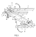
- the support 1 of the invention comprises a foot 2, removably mounted on the central section 3 of the beam P, by means of fixing means 2 a standards which allow to maintain the profile central 3, possibly in an inclined position.
- the beam P consists of a substantially straight central section 3 and provided with two rectilinear side arms 4 and 5 which are articulated at the ends 3 a and 3 b of the central section by means of articulation means 6 which will be more fully described later.
- the two ends 3 a and 3 b of the central section 3 are each secured to a lateral arm 4 and 5.
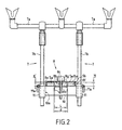
- the support elements 7 comprise a transverse bar 7 a and two vertical uprights 7 b .
- Figure 1 shows only one support element 7, that equipping the side arm 5. It is obvious that the side arm 4 can be equipped with a support element similar to the support element 7 whose description will follow with reference to the side arm 4.
- the transverse bar 7 a of the support element 7 is equipped with support members for one or more fishing rods 9.
- the support element 7 also includes a reinforcement bar 10.
- the reinforcement bar 10 is arranged in contact with the underside 5 d of the lateral arm 5 and is transverse to the lateral arm 5.
- Each of the two ends 10 a and 10 b of the reinforcement bar 10 is integral with a vertical upright 7 b which happens to be substantially perpendicular to the arm lateral 5 of the beam P, when the lateral arm 5 is in the extension of the central section 3.
- the reinforcing bar 10 comprises means 8 for its locking in position on the beam P.
- each vertical upright 7b is secured to one end 10 a, 10 b of the reinforcing bar 10 by means of a sleeve 11 wherein the amount 7 b is mounted sliding.
- the reinforcing bar 10 has a length slightly greater than the width of the lateral arm 5 so that the sleeves 11 are arranged on either side of the lateral arm 5 of the P-beam. In this way, the uprights 7 b can easily slide in the sleeves 11.
- the sleeves 11 also include means for blocking the upright 7 b which include, for example, levers 11 a which make it possible to maintain the upright 7 b in the sleeve 11, by friction between the internal surface of the sleeve 11 and the external surface of the upright 7 b .
- the uprights 7b are designed to be removable from the sleeves 11.
- the lateral arms 4 and 5 consist of two sections respectively 4 a , 4 b and 5 a , 5 b substantially straight and parallel ( Figure 1) and provided with transverse reinforcing rods 4 c and 5 c arranged towards the free end of each of the lateral arms 4 and 5.
- the sections 4 a , 4 b , 5 a and 5 b are spaced apart by a distance d greater than or equal to the width of the central section 3.
- the distance d will be very slightly greater than the width of the central section 3, to properly fit the central section 3 so as to reduce the possible torsional forces which can be exerted on each of the sections 4 a , 4b, 5 a and 5 b of the lateral arms 4 and 5.
- each lateral arm 4 and 5 is articulated relative to the central section 3 along an axis of rotation z ( Figures 1 and 3), by means of two pins 6 a and 6 b ( Figure 3) forming the articulation means 6.
- Each nipples 6 a and 6 b enter an oblong opening 6 c formed in the thickness e of the central profile 3.
- the nipples 6 a and 6 b are therefore capable of sliding in the oblong openings 6 c , thus making the lateral arm 4 , 5 movable in translation relative to the central profile 3.
- the pins 6 a and 6 b can be replaced by a rod connecting the two profiles 4 a , 4 b and 5a, 5 b respectively of each of the lateral arms 4 and 5.
- the length h of the oblong openings 6 c is such that when the lateral arms 4 and 5 are locked in the extension of the central profile 3, the pins 6 a and 6 b coming into abutment against the end 6 d of the oblong openings 6 c which is directed towards the center of the strip 3, the strip 3 is inserted over a length L 1 ( Figure 1), of the order of 4cm to 5cm, respectively between the sections 4a, 4b and 5a, 5b each side arm 4 and 5 which makes it possible to reinforce the mechanical resistance, in particular nt to the twists of each lateral arm.
- the locking means 12 of the lateral arms in the extension of the central section 3 comprise, for each lateral arm 4 or 5, a stop plate 12 a secured to the lateral arm considered and means for pressing the plate stop 12 a on the central profile 3 which comprise a threaded rod 12 b which cooperates with a thread formed in the thickness of the central profile 3 or with an insert or a nut introduced into the central profile 3 and a pressure member, by example, wheel type 12 c .
- the blocking of the stop plate 12 a by the wheel 12 c can be achieved by wedging a small peripheral portion of the stop plate 12 a under the wheel 12 c .
- the stop plate 12 a comprises a cutout 12 d capable of cooperating with the threaded rod 12 b .
- the pressure is exerted substantially at the center of the stop plate 12 a and the blocking of the lateral arm 4 or 5 in the extension of the central section 3 is therefore reinforced.
- clamping pressure means which sandwich the stop plate 12a and the central profile 3 so as to hold the stop plate 12 a against the profile central 3.
- the pins 6 a and 6 b are placed so that the threaded rod 12 b is introduced into the opening 12 d (FIG. 1), the thumb wheel 12 c is then brought into contact with the stop plate 12 a by screwing the threaded rod 12 b .
- the wheel 12 c pressed sufficiently against the stop plate 12 a makes it possible to prevent the lateral arms 4 and 5 from moving either in translation or in rotation relative to the central profile 3.
- the pins 6 a and 6 b are abutted against the end 6 d of the oblong opening 6 c so as to maximize the length L 1 (FIG. 1) of the central section 3 embedded between the sections 4 a , 4 b and 5 a , 5 b of the two side arms 4 and 5.
- a first advantage concerns the fisherman who, in the case of removable lateral arms, can easily reassemble the support of the invention since the lateral arms are interchangeable.
- the second advantage is a reduction in the manufacturing cost of the support of the present invention.
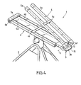
- the variant embodiment of the present invention which is shown in FIG. 4 has an articulation of the lateral arms produced by means of two rods 6 e and 6 f .
- the elements of this alternative embodiment common to the first embodiment shown in Figures 1 and 2 are referenced identically.
- the rod 6 a is integrated at the end 3 a of the central profile 3 and allows the articulation of the lateral arm 4 so that when the lateral arm 4 is folded over the central profile 3, the two profiles 4 a and 4 b are arranged on each side of the length of the central profile 3.
- the side arm 5 is articulated by means of a rod 6 f fixed on the central profile 3 so that when the side arm 5 is folded over the profile 3, it is located superimposed along its entire length on the central profile 3.
- each lateral arm 4, 5 is provided with locking means 12 in the extension of the central section 3 which comprise an abutment plate 12 a arranged so that, when each lateral arm is unfolded and under the effect of its own weight, the stop plate 12 a which is disposed at the end of each lateral arm 4 and 5 abuts against the central profile 3 or against a stop 3 c secured to the underside of the profile central 3, thus blocking the lateral arm 4 or 5 in the extension of the central profile 3.
- the advantage of this second embodiment is the fact of being able to completely fold back the lateral arms 4 and 5, without dismantling the foot 2 of the support 1 .
- the locking means in position 8 of the reinforcing bar 10 against the beam P comprise a reinforcing plate 8a disposed on the upper face 5 e of the lateral arm 5 opposite the face on which slides the reinforcement bar 10 and which at least partially covers the width of the lateral arm 5, so as to correctly block the reinforcement bar 10 against the lateral arm 5.
- the pressure means of the reinforcement plate 8a on the lateral arm 5 comprise a threaded rod 8b (FIG. 2) which secures the reinforcement bar 10 and the reinforcement plate 8a and which cooperates with a knurl 8c and a thread 8d formed in the thickness of the reinforcement bar 10.
- the thumb wheel 8 c when it is screwed into the reinforcement bar 10, exerts pressure on the reinforcement plate 8 a which keeps the latter pressed against the lateral arm 5. It is also possible, when the reinforcing bar 10 does not exhibit a sufficient thickness to provide the internal threaded rod 8b of a nut or a quick release cam.
- the reinforcement plate 8 a is provided with edges 8 e and 8 f ( Figure 2) which at least partially cover the thickness e 'of the sections 5 a , 5 b , serve as a guide for the sliding of the reinforcing bar 10 on the lateral arm 5 and which, also, prevent any rotation of the bar. reinforcement 10 relative to the lateral arm
- a spacer 8 g (FIG. 2) is arranged between the two sections 5 a , 5 b of the lateral arm 5.
- This spacer 8 g has a width L substantially equal to the distance d separating the sections 4 a and 4 b , and a height H less than or equal and, preferably, substantially equal to the thickness e ' of the sections 5 a , 5 b .
- the presence of this spacer 8 g makes it possible to stiffen the lateral arm 5 by forming a solid portion, therefore more resistance to torsion, at the level of the support element 7, which further reinforces the action of the reinforcing bar 10.
- L 'spacer 8 g is integral with the reinforcement plate 8 a and / or the reinforcement bar 10.
- the reinforcement bar 10 can, in all cases, when it is slidably mounted on the beam P , be detached from the beam P by sliding to the free end of the lateral arm 5.
- the arrangement of the reinforcing bar 10 and the reinforcing plate 8 a can be reversed, that is to say that the reinforcing bar 10 can be arranged on the face 5 e of the lateral arm 5 Likewise, it is possible to adapt the arrangement of the various elements of the first locking means 8 to a support element 7 comprising only a rectilinear upright 7b .
Landscapes
- Life Sciences & Earth Sciences (AREA)
- Environmental Sciences (AREA)
- Animal Husbandry (AREA)
- Biodiversity & Conservation Biology (AREA)
- Fishing Rods (AREA)
- Tents Or Canopies (AREA)
- Mutual Connection Of Rods And Tubes (AREA)
Claims (13)
- Träger (1) für eine oder mehrere Angelruten des Typs, der einen Balken (P) umfasst, auf dem mindestens zwei Trägerelemente (7) einer oder mehrerer Angelruten befestigt sind, dadurch gekennzeichnet, dass jedes Trägerelement (7) eine Verstärkungsstange (10) aufweist, die quer zu dem Balken (P) verläuft und mit einer der Unter- oder Oberseiten (4d, 4e) des Balkens (P) in Kontakt steht und mindestens einen geradlinigen Ständer (7b) aufweist, der auf der Verstärkungsstange (10) befestigt ist und der im Wesentlichen senkrecht zu dem Balken (P) verläuft, und dass die Verstärkungsstange (10) mindestens eines der Trägerelemente (7) gleitend in bezug auf den Balken (P) entlang der Längsachse des Balkens (P) befestigt und mit Einrichtungen zur Arretierung (8) in einer Position in bezug auf den Balken (P) ausgestattet ist.
- Träger (1) nach Anspruch 1, dadurch gekennzeichnet, dass der Balken umfasst:ein zentrales Profil (3);zwei seitliche Arme (4, 5), die im Wesentlichen geradlinig sind und in bezug auf das zentrale Profil (3) abnehmbar und/oder beweglich sind in der Weise, dass sie im Wesentlichen über dem zentralen Profil (3) angeordnet sein können, und die in der Verlängerung des zentralen Profils (3) positioniert sein können.
- Träger (1) nach Anspruch 2, dadurch gekennzeichnet, dass jeder seitliche Arm (4, 5) mit dem zentralen Profil (3) entlang einer Rotationsachse (z) quer zur Längsachse des zentralen Profils (3) mittels eines Gelenks so verbunden ist, dass jeder seitliche Arm (4, 5) auf das zentrale Profil (3) zurückgeklappt oder in der Verlängerung des zentralen Profils ausgerichtet werden kann.
- Träger (1) nach Anspruch 2, dadurch gekennzeichnet, dass jeder seitliche Arm (4, 5) mit dem zentralen Profil (3) mittels zweier Nippel (Ansatzkuppen) (6a, 6b) gelenkig verbunden ist, die jeweils mit einer länglichen Öffnung (6c) kooperieren, die in der Dicke (e) des zentralen Profils (3) so angeordnet ist, dass sie gegebenenfalls eine Verschiebung der seitlichen Arme (4, 5) gegenüber dem zentralen Profil (3) erlauben und jeden der seitlichen Arme (4, 5) drehbar im Verhältnis zu dem zentralen Profil (3) machen.
- Träger nach einem der Ansprüche 2 bis 4, dadurch gekennzeichnet, dass er außerdem Einrichtungen zur Arretierung (12) des seitlichen Arms in der Verlängerung des zentralen Profils (3) aufweist, wobei diese Einrichtungen umfassen:eine Anschlagplatte (12a), die mit dem seitlichen Arm (4, 5) fest verbunden ist, und gegebenenfallsEinrichtungen (12b, 12c, 12d) zum Anpressen der Anschlagplatte (12a) an das zentrale Profil (3).
- Träger (1) nach einem der Ansprüche 2 bis 5, dadurch gekennzeichnet, dass jeder der seitlichen Arme (4, 5) zwei Profile (4a, 4b, 5a, 5b) umfasst, die im Wesentlichen geradlinig und parallel sind und die einen Abstand (d) voneinander haben.
- Träger nach Anspruch 6, dadurch gekennzeichnet, dass der die beiden Profile (4a, 4b, 5a, 5b) des seitlichen Arms (4, 5) trennende Abstand (d) etwas größer ist als die Breite (l) des zentralen Profils (3) in der Weise, dass dann, wenn der seitliche Arm (4, 5) einmal positioniert und in der Verlängerung des zentralen Profils (3) arretiert ist, das zentrale Profil (3) zwischen den beiden Profilen (4a, 4b, 5a, 5b) des seitlichen Arms (4, 5) eingeschlossen ist.
- Träger (1) nach Anspruch 6 oder 7, dadurch gekennzeichnet, dass die Verstärkungsstange (10) ein Abstandsstück (8g) aufweist, das zwischen den parallelen Profilen (4a, 4b, 5a, 5b) angeordnet ist, wobei die Breite (L) des Abstandsstückes (8g) im Wesentlichen gleich dem Abstand (d) ist, der die beiden parallelen Profile (4a, 4b, 5a, 5b) voneinander trennt.
- Träger (1) nach nach einem der Ansprüche 1 bis 8, dadurch gekennzeichnet, dass das Trägerelement (7) von dem Balken ((P) abnehmbar ist.
- Träger (1) nach einem der Ansprüche 1 bis 9, dadurch gekennzeichnet, dass jedes Trägerelement (7) zwei vertikale Ständer (7b) umfasst, wobei jeder der vertikalen Ständer (7b) mit einem Ende (10a, 10b) der Verstärkungsstange (10) fest verbunden ist.
- Träger (1) nach einem der Ansprüche 1 bis 10, dadurch gekennzeichnet, dass die Verstärkungsstange (10) an jedem ihrer Enden (10a, 10b) eine Muffe (11) aufweist, in der einer der Ständer (8) des Trägerelements (7) gleitend befestigt ist und die mit Einrichtungen (11a) zur Arretierung des Ständers (8) ausgestattet ist, wobei die Muffen (11) beiderseits des Balkens (P) angeordnet sind.
- Träger (1) für eine Angelrute nach einem der Ansprüche 1 bis 11, dadurch gekennzeichnet, dass die Einrichtungen (8) zur Blockierung der Verstärkungsstange (10) in der richtigen Position in bezug auf den Balken (P) eine Verstärkungsplatte (8a), die auf der Seite des Balkens (P) angeordnet ist, die der Seite des Balkens gegenüberliegt, auf der die Verstärkungsstange (10) gleitet, und Einrichtungen (8b, 8c) zum Anpressen der Verstärkungsstange (13) an den Balken (P) umfassen.
- Träger (1) nach Anspruch 12, dadurch gekennzeichnet, dass die Verstärkungsplatte (8a) Ränder (8e, 8f) aufweist, welche die Dicke (e) des Balkens (P) mindestens teilweise bedecken.
Applications Claiming Priority (4)
| Application Number | Priority Date | Filing Date | Title |
|---|---|---|---|
| FR9815153 | 1998-11-27 | ||
| FR9815154 | 1998-11-27 | ||
| FR9815154A FR2786366B1 (fr) | 1998-11-27 | 1998-11-27 | Support pour canne a peche |
| FR9815153A FR2786365B1 (fr) | 1998-11-27 | 1998-11-27 | Support pour canne a peche resistant aux torsions |
Publications (2)
| Publication Number | Publication Date |
|---|---|
| EP1004239A1 EP1004239A1 (de) | 2000-05-31 |
| EP1004239B1 true EP1004239B1 (de) | 2003-09-17 |
Family
ID=26234684
Family Applications (1)
| Application Number | Title | Priority Date | Filing Date |
|---|---|---|---|
| EP99490038A Expired - Lifetime EP1004239B1 (de) | 1998-11-27 | 1999-11-25 | Torsionsfester Angelrutenhalter |
Country Status (3)
| Country | Link |
|---|---|
| EP (1) | EP1004239B1 (de) |
| AT (1) | ATE249737T1 (de) |
| DE (1) | DE69911351T2 (de) |
Families Citing this family (2)
| Publication number | Priority date | Publication date | Assignee | Title |
|---|---|---|---|---|
| US9090214B2 (en) | 2011-01-05 | 2015-07-28 | Orbotix, Inc. | Magnetically coupled accessory for a self-propelled device |
| US11985964B2 (en) * | 2018-08-03 | 2024-05-21 | Kevin F Lohmeier | Fishing rod holder |
Family Cites Families (5)
| Publication number | Priority date | Publication date | Assignee | Title |
|---|---|---|---|---|
| GB2201322B (en) * | 1987-02-18 | 1991-08-28 | K M Tackle Developments Limite | Rod support unit for anglers |
| GB8911231D0 (en) * | 1989-05-16 | 1989-07-05 | Thornhill Alan | Fishing bite indicator |
| GB2306092A (en) * | 1995-10-14 | 1997-04-30 | Nash Kevin Tackle Ltd | Fishing rod support |
| GB2313030B (en) * | 1996-05-17 | 2000-01-19 | James Leary | Fishing rod rests |
| GB2321580B (en) * | 1997-01-24 | 1998-12-16 | Spring Sunglow Ind Co Ltd | Fishing kit |
-
1999
- 1999-11-25 EP EP99490038A patent/EP1004239B1/de not_active Expired - Lifetime
- 1999-11-25 DE DE69911351T patent/DE69911351T2/de not_active Expired - Fee Related
- 1999-11-25 AT AT99490038T patent/ATE249737T1/de not_active IP Right Cessation
Also Published As
| Publication number | Publication date |
|---|---|
| EP1004239A1 (de) | 2000-05-31 |
| DE69911351T2 (de) | 2004-06-24 |
| DE69911351D1 (de) | 2003-10-23 |
| ATE249737T1 (de) | 2003-10-15 |
Similar Documents
| Publication | Publication Date | Title |
|---|---|---|
| EP1563876A1 (de) | Langlaufski | |
| EP0561774A1 (de) | Faltbarer rollstuhl. | |
| EP0900037A1 (de) | Zusammensetzbarer stuhl | |
| EP1004239B1 (de) | Torsionsfester Angelrutenhalter | |
| FR2475871A3 (fr) | Bras support pour siege ou fauteuil comportant un accoudoir relevable | |
| EP1488770A1 (de) | Hebestuhl mit automatisch veränderlicher Neigung der Rückenlehne | |
| EP0681799B1 (de) | Blokiervorrichtung für eine Verlängerung Bezüglich eines Möbelstückes, und Möbelstück damit Ausgestattet | |
| EP0783856B1 (de) | Lattenrost | |
| FR2786366A1 (fr) | Support pour canne a peche | |
| EP2862440B1 (de) | Abroller Rutenauflage | |
| EP2471700A1 (de) | Klapprad mit Stabilisierungssystem | |
| EP1721550B1 (de) | Krankenbett mit vollständiger Seitenlehne | |
| FR2487653A1 (fr) | Siege transformable | |
| FR2786365A1 (fr) | Support pour canne a peche resistant aux torsions | |
| EP0282385B1 (de) | Vorrichtung zur Verankerung an Dachsparren bei Dacharbeiten | |
| FR2685606A1 (fr) | Tabouret de peche avec support de canne(s). | |
| EP0532081B1 (de) | Vorrichtung zum Weichmachen | |
| FR2815527A1 (fr) | Lit a elements de barrieres coulissants et articules | |
| FR2686940A3 (en) | Folding structure which can be used as a gangway and/or ladder | |
| EP0076710B1 (de) | Vorrichtung zum Regeln der Stellung einer Trageplatte | |
| FR2758247A1 (fr) | Chaise, notamment une chaise d'ecole | |
| FR2844689A1 (fr) | Agencement d'assise modulable d'un siege transformable en couchage et element meublant obtenu | |
| BE879829A (fr) | Siege de type transatlantique | |
| FR2684310A1 (fr) | Bascule reglable, notamment pour jouets. | |
| FR2771268A1 (fr) | Nappe deformable notamment pour fauteuils, et fauteuils utilisant cette nappe |
Legal Events
| Date | Code | Title | Description |
|---|---|---|---|
| PUAI | Public reference made under article 153(3) epc to a published international application that has entered the european phase |
Free format text: ORIGINAL CODE: 0009012 |
|
| AK | Designated contracting states |
Kind code of ref document: A1 Designated state(s): AT BE CH CY DE DK ES FI FR GB GR IE IT LI LU MC NL PT SE |
|
| AX | Request for extension of the european patent |
Free format text: AL;LT;LV;MK;RO;SI |
|
| 17P | Request for examination filed |
Effective date: 20000731 |
|
| AKX | Designation fees paid |
Free format text: AT BE CH CY DE DK ES FI FR GB GR IE IT LI LU MC NL PT SE |
|
| 17Q | First examination report despatched |
Effective date: 20030115 |
|
| GRAH | Despatch of communication of intention to grant a patent |
Free format text: ORIGINAL CODE: EPIDOS IGRA |
|
| GRAS | Grant fee paid |
Free format text: ORIGINAL CODE: EPIDOSNIGR3 |
|
| GRAA | (expected) grant |
Free format text: ORIGINAL CODE: 0009210 |
|
| AK | Designated contracting states |
Kind code of ref document: B1 Designated state(s): AT BE CH CY DE DK ES FI FR GB GR IE IT LI LU MC NL PT SE |
|
| PG25 | Lapsed in a contracting state [announced via postgrant information from national office to epo] |
Ref country code: IE Free format text: LAPSE BECAUSE OF FAILURE TO SUBMIT A TRANSLATION OF THE DESCRIPTION OR TO PAY THE FEE WITHIN THE PRESCRIBED TIME-LIMIT Effective date: 20030917 Ref country code: FI Free format text: LAPSE BECAUSE OF FAILURE TO SUBMIT A TRANSLATION OF THE DESCRIPTION OR TO PAY THE FEE WITHIN THE PRESCRIBED TIME-LIMIT Effective date: 20030917 Ref country code: AT Free format text: LAPSE BECAUSE OF FAILURE TO SUBMIT A TRANSLATION OF THE DESCRIPTION OR TO PAY THE FEE WITHIN THE PRESCRIBED TIME-LIMIT Effective date: 20030917 |
|
| REG | Reference to a national code |
Ref country code: GB Ref legal event code: FG4D Free format text: NOT ENGLISH |
|
| REG | Reference to a national code |
Ref country code: CH Ref legal event code: EP |
|
| GBT | Gb: translation of ep patent filed (gb section 77(6)(a)/1977) | ||
| REF | Corresponds to: |
Ref document number: 69911351 Country of ref document: DE Date of ref document: 20031023 Kind code of ref document: P |
|
| REG | Reference to a national code |
Ref country code: IE Ref legal event code: FG4D Free format text: FRENCH |
|
| PG25 | Lapsed in a contracting state [announced via postgrant information from national office to epo] |
Ref country code: LU Free format text: LAPSE BECAUSE OF NON-PAYMENT OF DUE FEES Effective date: 20031125 Ref country code: CY Free format text: LAPSE BECAUSE OF FAILURE TO SUBMIT A TRANSLATION OF THE DESCRIPTION OR TO PAY THE FEE WITHIN THE PRESCRIBED TIME-LIMIT Effective date: 20031125 |
|
| PG25 | Lapsed in a contracting state [announced via postgrant information from national office to epo] |
Ref country code: MC Free format text: LAPSE BECAUSE OF NON-PAYMENT OF DUE FEES Effective date: 20031130 Ref country code: LI Free format text: LAPSE BECAUSE OF NON-PAYMENT OF DUE FEES Effective date: 20031130 Ref country code: CH Free format text: LAPSE BECAUSE OF NON-PAYMENT OF DUE FEES Effective date: 20031130 |
|
| PG25 | Lapsed in a contracting state [announced via postgrant information from national office to epo] |
Ref country code: SE Free format text: LAPSE BECAUSE OF FAILURE TO SUBMIT A TRANSLATION OF THE DESCRIPTION OR TO PAY THE FEE WITHIN THE PRESCRIBED TIME-LIMIT Effective date: 20031217 Ref country code: GR Free format text: LAPSE BECAUSE OF FAILURE TO SUBMIT A TRANSLATION OF THE DESCRIPTION OR TO PAY THE FEE WITHIN THE PRESCRIBED TIME-LIMIT Effective date: 20031217 Ref country code: DK Free format text: LAPSE BECAUSE OF FAILURE TO SUBMIT A TRANSLATION OF THE DESCRIPTION OR TO PAY THE FEE WITHIN THE PRESCRIBED TIME-LIMIT Effective date: 20031217 |
|
| PG25 | Lapsed in a contracting state [announced via postgrant information from national office to epo] |
Ref country code: PT Free format text: LAPSE BECAUSE OF FAILURE TO SUBMIT A TRANSLATION OF THE DESCRIPTION OR TO PAY THE FEE WITHIN THE PRESCRIBED TIME-LIMIT Effective date: 20031226 |
|
| PG25 | Lapsed in a contracting state [announced via postgrant information from national office to epo] |
Ref country code: ES Free format text: LAPSE BECAUSE OF FAILURE TO SUBMIT A TRANSLATION OF THE DESCRIPTION OR TO PAY THE FEE WITHIN THE PRESCRIBED TIME-LIMIT Effective date: 20031228 |
|
| REG | Reference to a national code |
Ref country code: IE Ref legal event code: FD4D |
|
| PGFP | Annual fee paid to national office [announced via postgrant information from national office to epo] |
Ref country code: NL Payment date: 20040511 Year of fee payment: 5 Ref country code: GB Payment date: 20040511 Year of fee payment: 5 |
|
| PGFP | Annual fee paid to national office [announced via postgrant information from national office to epo] |
Ref country code: DE Payment date: 20040526 Year of fee payment: 5 |
|
| PGFP | Annual fee paid to national office [announced via postgrant information from national office to epo] |
Ref country code: BE Payment date: 20040608 Year of fee payment: 5 |
|
| REG | Reference to a national code |
Ref country code: CH Ref legal event code: PL |
|
| PLBE | No opposition filed within time limit |
Free format text: ORIGINAL CODE: 0009261 |
|
| STAA | Information on the status of an ep patent application or granted ep patent |
Free format text: STATUS: NO OPPOSITION FILED WITHIN TIME LIMIT |
|
| 26N | No opposition filed |
Effective date: 20040618 |
|
| PG25 | Lapsed in a contracting state [announced via postgrant information from national office to epo] |
Ref country code: GB Free format text: LAPSE BECAUSE OF NON-PAYMENT OF DUE FEES Effective date: 20041125 |
|
| PG25 | Lapsed in a contracting state [announced via postgrant information from national office to epo] |
Ref country code: BE Free format text: LAPSE BECAUSE OF NON-PAYMENT OF DUE FEES Effective date: 20041130 |
|
| PGFP | Annual fee paid to national office [announced via postgrant information from national office to epo] |
Ref country code: FR Payment date: 20050420 Year of fee payment: 6 |
|
| BERE | Be: lapsed |
Owner name: *AMOURELLE OLIVIER Effective date: 20041130 |
|
| PG25 | Lapsed in a contracting state [announced via postgrant information from national office to epo] |
Ref country code: NL Free format text: LAPSE BECAUSE OF NON-PAYMENT OF DUE FEES Effective date: 20050601 Ref country code: DE Free format text: LAPSE BECAUSE OF NON-PAYMENT OF DUE FEES Effective date: 20050601 |
|
| GBPC | Gb: european patent ceased through non-payment of renewal fee |
Effective date: 20041125 |
|
| NLV4 | Nl: lapsed or anulled due to non-payment of the annual fee |
Effective date: 20050601 |
|
| PG25 | Lapsed in a contracting state [announced via postgrant information from national office to epo] |
Ref country code: IT Free format text: LAPSE BECAUSE OF NON-PAYMENT OF DUE FEES;WARNING: LAPSES OF ITALIAN PATENTS WITH EFFECTIVE DATE BEFORE 2007 MAY HAVE OCCURRED AT ANY TIME BEFORE 2007. THE CORRECT EFFECTIVE DATE MAY BE DIFFERENT FROM THE ONE RECORDED. Effective date: 20051125 |
|
| PG25 | Lapsed in a contracting state [announced via postgrant information from national office to epo] |
Ref country code: FR Free format text: LAPSE BECAUSE OF NON-PAYMENT OF DUE FEES Effective date: 20060731 |
|
| REG | Reference to a national code |
Ref country code: FR Ref legal event code: ST Effective date: 20060731 |
|
| BERE | Be: lapsed |
Owner name: *AMOURELLE OLIVIER Effective date: 20041130 |