EP1002991A2 - Apparatus for the height-adjustable suspension of an electric device - Google Patents
Apparatus for the height-adjustable suspension of an electric device Download PDFInfo
- Publication number
- EP1002991A2 EP1002991A2 EP99120780A EP99120780A EP1002991A2 EP 1002991 A2 EP1002991 A2 EP 1002991A2 EP 99120780 A EP99120780 A EP 99120780A EP 99120780 A EP99120780 A EP 99120780A EP 1002991 A2 EP1002991 A2 EP 1002991A2
- Authority
- EP
- European Patent Office
- Prior art keywords
- drum
- winding
- winding drum
- cover
- holding cord
- Prior art date
- Legal status (The legal status is an assumption and is not a legal conclusion. Google has not performed a legal analysis and makes no representation as to the accuracy of the status listed.)
- Granted
Links
- 239000000725 suspension Substances 0.000 title 1
- 238000004804 winding Methods 0.000 claims abstract description 93
- 239000000463 material Substances 0.000 claims description 3
- 238000000034 method Methods 0.000 description 3
- 230000002093 peripheral effect Effects 0.000 description 2
- 239000004809 Teflon Substances 0.000 description 1
- 229920006362 Teflon® Polymers 0.000 description 1
- 230000015572 biosynthetic process Effects 0.000 description 1
- 230000000903 blocking effect Effects 0.000 description 1
- 238000010276 construction Methods 0.000 description 1
- 229920001296 polysiloxane Polymers 0.000 description 1
Images


Classifications
-
- F—MECHANICAL ENGINEERING; LIGHTING; HEATING; WEAPONS; BLASTING
- F21—LIGHTING
- F21V—FUNCTIONAL FEATURES OR DETAILS OF LIGHTING DEVICES OR SYSTEMS THEREOF; STRUCTURAL COMBINATIONS OF LIGHTING DEVICES WITH OTHER ARTICLES, NOT OTHERWISE PROVIDED FOR
- F21V27/00—Cable-stowing arrangements structurally associated with lighting devices, e.g. reels
Definitions
- the invention relates to an arrangement for height-adjustable hanging bracket an electrically operable device and in particular a holder for a hanging lamp.
- the electrically operated device is at one end attached a tether, which also the power supply lines for the Device includes.
- the tether is on a winding drum wound, which is rotatably mounted on a drum holder, wherein the drum holder in turn for attachment to, for example, one Ceiling is formed.
- a winding drum in your Spring motor driving winding direction and one by means of a freewheel device effective braking device provided in the unwinding direction, which matched to each other and to the weight of the electrically operated device are that the device is manually operated to a desired height can be set and gets stuck there.
- From DE 44 11 990 A1 is a lamp holder with one on a drum holder horizontally mounted conically tapered winding drum known.
- the winding drum, the spring device, the braking device and the drum holder are attached by a cover attached to the drum structure covers, which has an opening through which the tether the cover enforced.
- This funnel-shaped opening guides the tether the large diameter area of the conical winding drum.
- the winding drum has a surface with reduced adhesion to the tether so that the tether when winding on the winding drum due to the Tensile force of the spring force in the direction of the small diameter area the winding drum slips and there in contact with one already on the winding drum wound cord position reached. It is therefore an orderly winding the cord is reached.
- the spring device is as Roll spring formed in which a leaf spring from a supply spool to a Work coil is wrapped.
- a disadvantage of this known holder is the complex spring device and the complex construction of the guide for the tether, which is required in order to wind up the tether in an orderly manner to ensure the winding drum.
- the invention is based on an arrangement for height-adjustable hanging bracket of an electrically operated device, which a winding drum for winding up a power supply line for the electrical Device has extensive flexible tether, at the free end of the electrical Device is attachable, the winding drum by a spring device is driven in a winding direction and a turning axis, one in Direction of the axis of rotation extending drum shell and two den Drum shell includes axially closing drum disks, which prevent that the tether jumps from the winding drum when winding.
- the arrangement further comprises a drum holder which rotatably supports the winding drum, which are essentially horizontal to the axis of rotation Is mounted on an object, such as a ceiling, and it also includes a firmly connected to the drum holder and the Winding drum at least partially surrounding cover which the aforementioned Components should at least partially hide from a viewer and which has an outlet recess on which the tether the Cover penetrated.
- a drum holder which rotatably supports the winding drum, which are essentially horizontal to the axis of rotation Is mounted on an object, such as a ceiling, and it also includes a firmly connected to the drum holder and the Winding drum at least partially surrounding cover which the aforementioned Components should at least partially hide from a viewer and which has an outlet recess on which the tether the Cover penetrated.
- the drum disks also cover enforce such that the outlet recess at least from the Cover and is limited by the drum discs. This has the consequence that the guiding function of feeding the tether to the winding drum together is provided by the drum disks and the cover.
- the arrangement is designed such that the tether Exit recess penetrates so that it covers the cover substantially not touched if the arrangement as intended on the object is mounted and the tether extends vertically downwards.
- the Exit recess on the cover in particular as a slot, continued in such a way that they start from one adjacent to the drum disks Area continues in the winding direction of the winding drum. This will avoid contact between the tether and the cover, if the tether is in the properly installed state the arrangement does not extend vertically downwards.
- the winding drum is advantageously designed as a single-track winding drum, d. that is, the tether on the winding drum passes in layers one above the other and not next to each other for arrangement.
- This has been linked to the features described above as a particularly preferred embodiment therefore, because the single-track winding drum has a reduced Capacity to hold cord, but on the other hand an orderly Supported winding of the tether on its own.
- this winding drum offers the usual Adequate room heights and the usual cord diameter Take-up capacity, d. H. a sufficient height adjustment range for the pendant lamp.
- This tether guide comprises two guide walls, which are in radial extension of the drum disks over a peripheral portion of the drum disk extend.
- the winding drum can be located on the peripheral partial region a winding radius is reached and held on the winding drum, that exceeds the radius of the drum disc.
- the winding drum as a single-track winding drum can become one noticeable increase in winding capacity.
- the spring inserted into the spring device is advantageously a spiral spring.
- the coil spring is a comparatively inexpensive spring, the use of which is due the reduced friction between the tether and the arrangement is possible becomes.
- a comparatively low spring force can therefore be selected which are sufficient even when implemented by a spiral spring Uniform provision of spring force over the entire winding area provides.
- the tether is advantageously designed as a hose line, which at least two separately isolated power supply lines and one has the sheath surrounding the power supply line.
- Hose line has only a limited flexibility, but is in Connection with the arrangement described above is therefore suitable because it is inexpensive and because of the reduced friction between Holding cord and cover their limited flexibility even at low Temperature does not have a significantly disadvantageous consequence.
- the coat is the Hose line advantageously formed from PVC material and the power supply lines do not adhere to the coat.
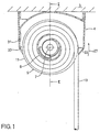
- the lamp holder 1 comprises a winding drum 5 with one in the ceiling 3 mounted state horizontally extending axis of rotation 7, a Drum jacket 9 and two drum disks axially delimiting the drum jacket 11.
- a power cable 13 is wound onto the winding drum 5, which two surrounded by a PVC jacket 15 and separately insulated power supply lines 17 has.
- the power cable 13 meets the German standard DIN VDE 0281-5 and has the designation code H03VV-F-2x0.75.
- the power cord 13 is flexible in itself, but it resists changing it Curvature with a certain toughness, which is particularly true in the low Temperatures at which the PVC material is less supple increases is. In order to at least somewhat reduce this toughness, the power supply lines adhere 17 not on the PVC jacket 15.
- the lamp holder 1 further comprises a sliding contact device 19 to the power supply lines 17 of the power cable 13 with lines 21 for connection to connect to a ceiling outlet.
- the winding drum 5 is rotatably mounted on a drum holder 23, which to be screwed to the ceiling 3. Between the drum holder 23 and the Winding drum 5, a spiral spring 25 is turned on, which the winding drum 5 with respect to the drum holder 23 into one indicated by an arrow 27 Drives winding direction.
- the spring force is on the weight of the luminaire matched, wherein a freewheel device 6 is provided, which with a Friction device 29 is coupled such that it only in the unwinding direction is effective and the unwinding of the power cable 13 from the winding drum 5 due to the weight of the lamp is prevented.
- the drum holder 23 On the upper part of the drum holder 23 there are also two guide walls 37 formed, each of which is in radial extension one of the drum disks 11 extends. Between these guide walls 37 is with the power cable completely wound on the winding drum 5 13 a layer 39 of the power cable 13 over a partial circumference of the winding drum 5 added so that a going beyond the radius of the drum disks 11 Area for winding the power cable 13 are used can without the power cable 13 slides from the winding drum 5.
- the drum holder 23 and essential parts of the winding drum 5 are through a cover 31 attached to the drum holder 23 from view obscured by the viewer.
- the cover 31 has a circumferential direction of the winding drum 5 extending slot 33, the drum disks 11th push through.
- the longitudinal flanks of the slot 33 only have one slight distance to the outer surfaces of the drum disks 11, and in In the longitudinal direction, the slot 33 is dimensioned such that it has a slight Has distance to the end faces of the drum disks 11.
- the power cord 13 passes through the slot 33, whereby it passes through the drum disk 11 on both sides is led. When the power cord 13 is vertical as shown in FIG. 1 extends downward, it does not touch the cover 31.
- the lamp holder 1 a shown in FIGS. 3 and 4 differs from that embodiment described above only in the design of the Slot 33a of cover 31a.
- the slot 33a is namely compared to the embodiment described above in its longitudinal direction in Winding direction 27a of the winding drum 5a and in particular up to extended a slot end 35 closer to the ceiling 3a.
- Fig. 4 is the course of the power cable 13a during the winding process shown.
- the power cable 13 is flexible, but changes its Radius of curvature offers a certain resistance in the form of a toughness, so that it is not tangent to the winding drum when winding extends vertically downward, but approximately as shown in Figure 4 has a curved course.
- slit 33a in the winding direction 27a of the drum extends to its slot end 35, this can Power cable 13a take the curved shape preferred by him, without in To come into contact with the cover 31a. This also lies during a rapid winding process an essentially negligible friction between the components of the lamp holder 1a and the power cable 13a.
- the position of the slot end 35 on the cover 31 is chosen so that a tangentially and rectilinearly extending away from the full winding drum 5a Power cable 13a 'without contact with the slot end 35, starting from one Point P extends away from the winding drum 5a, which is in the winding direction 27 is offset from an horizontal 38 by an angle ⁇ of approximately 80 °.
- a such dimensioning of the slot 33a enables even at comparatively low Room temperatures and the associated low flexibility of the power cable 13a, good functioning of the lamp holder 1a.
Landscapes
- Engineering & Computer Science (AREA)
- General Engineering & Computer Science (AREA)
- Storing, Repeated Paying-Out, And Re-Storing Of Elongated Articles (AREA)
- Storage Of Web-Like Or Filamentary Materials (AREA)
- Holders For Apparel And Elements Relating To Apparel (AREA)
- Tables And Desks Characterized By Structural Shape (AREA)
- Supports Or Holders For Household Use (AREA)
Abstract
Description
Die Erfindung betrifft eine Anordnung zur höhenveränderbaren hängenden Halterung eines elektrisch betreibbaren Geräts und insbesondere eine Halterung für eine Hängeleuchte.The invention relates to an arrangement for height-adjustable hanging bracket an electrically operable device and in particular a holder for a hanging lamp.
Bei einer solchen Halterung wird das elektrisch betreibbare Gerät an einem Ende einer Halteschnur befestigt, welche auch die Stromzuführungsleitungen für das Gerät umfaßt. Mit seinem anderen Ende ist die Halteschnur auf eine Wickeltrommel gewickelt, welche an einer Trommelhalterung drehbar gelagert ist, wobei die Trommelhalterung wiederum zur Befestigung an beispielsweise einer Zimmerdecke ausgebildet ist. Es sind ferner ein die Wickeltrommel in ihrer Aufwickelrichtung antreibender Federmotor und eine mittels einer Freilaufeinrichtung in Abwickelrichtung wirksame Bremseinrichtung vorgesehen, welche aufeinander und auf das Gewicht des elektrisch betreibbaren Geräts derart abgestimmt sind, daß das Gerät durch Handbetätigung auf eine gewünschte Höhe eingestellt werden kann und dort hängen bleibt.With such a holder, the electrically operated device is at one end attached a tether, which also the power supply lines for the Device includes. With its other end, the tether is on a winding drum wound, which is rotatably mounted on a drum holder, wherein the drum holder in turn for attachment to, for example, one Ceiling is formed. There is also a winding drum in your Spring motor driving winding direction and one by means of a freewheel device effective braking device provided in the unwinding direction, which matched to each other and to the weight of the electrically operated device are that the device is manually operated to a desired height can be set and gets stuck there.
Probleme treten bei derartigen bekannten Halterungen auf hinsichtlich der Abstimmung der Federkraft auf das Leuchtengewicht und beim Aufwickeln auftretender Reibungskräfte, sowie dahingehend, daß die Halteschnur dazu neigt, auf der Wickeltrommel ungeordnet aufgewickelt zu werden, was zu einer verringerten Aufwickelkapazität und einem Blockieren der Wickeltrommel führen kann.Problems arise with such known mounts in terms of tuning the spring force on the weight of the luminaire and when it is wound up Frictional forces, and in that the tether tends to the winding drum to be wound up disorderly, resulting in a reduced Winding capacity and blocking the winding drum can result.
Aus DE 44 11 990 A1 ist eine Leuchtenhalterung mit einer an einer Trommelhalterung horizontal gelagerten sich konisch verjüngenden Wickeltrommel bekannt. Die Wickeltrommel, die Federeinrichtung, die Bremseinrichtung und die Trommelhalterung werden von einer an der Trommelhallterung befestigten Abdeckung überdeckt, welche eine Öffnung aufweist, durch die die Halteschnur die Abdeckung durchsetzt. Diese trichterartig ausgebildete Öffnung führt die Halteschnur dem Bereich großen Durchmessers der konischen Wickeltrommel zu. Die Wickeltrommel weist eine Oberfläche mit verringerter Haftung für die Halteschnur auf so daß die Halteschnur beim Aufwickeln auf die Wickeltrommel aufgrund der Zugwirkung der Federkraft in Richtung zu dem Bereich geringen Durchmessers der Wickeltrommel abrutscht und dort in Anlage an eine bereits auf die Wickeltrommel aufgewickelte Schnurlage gelangt. Es ist somit ein geordnetes Aufwickeln der Haltschnur erreicht. Um eine über den gesamtem Abwickelbereich weitgehend gleichbleibende Federkraft bereitzustellen, ist die Federeinrichtung als Rollfeder ausgebildet, bei welcher eine Blattfeder von einer Vorratsspule auf eine Arbeitsspule umgewickelt wird.From DE 44 11 990 A1 is a lamp holder with one on a drum holder horizontally mounted conically tapered winding drum known. The winding drum, the spring device, the braking device and the drum holder are attached by a cover attached to the drum structure covers, which has an opening through which the tether the cover enforced. This funnel-shaped opening guides the tether the large diameter area of the conical winding drum. The winding drum has a surface with reduced adhesion to the tether so that the tether when winding on the winding drum due to the Tensile force of the spring force in the direction of the small diameter area the winding drum slips and there in contact with one already on the winding drum wound cord position reached. It is therefore an orderly winding the cord is reached. To a large extent across the entire development area To provide constant spring force, the spring device is as Roll spring formed in which a leaf spring from a supply spool to a Work coil is wrapped.
Als nachteilig erweisen sich bei dieser bekannten Halterung die aufwendige Federeinrichtung und die aufwendige Konstruktion der Führung für die Halteschnur, welche erforderlich ist, um ein geordnetes Aufwickeln der Halteschnur auf die Wickeltrommel zu gewährleisten.A disadvantage of this known holder is the complex spring device and the complex construction of the guide for the tether, which is required in order to wind up the tether in an orderly manner to ensure the winding drum.
Es ist somit eine Aufgabe der vorliegenden Erfindung, eine vereinfachte Halterung der geschilderten Art bereitzustellen.It is therefore an object of the present invention to provide a simplified bracket to provide the described type.
Die Erfindung geht hierbei aus von einer Anordnung zur höhenveränderbaren hängenden Halterung eines elektrisch betreibbaren Geräts, welche eine Wickeltrommel zum Aufwickeln einer Stromzuführungsleitungen für das elektrische Gerät umfassende flexible Halteschnur aufweist, an deren freiem Ende das elektrische Gerät befestigbar ist, wobei die Wickeltrommel von einer Federeinrichtung in eine Aufwickelrichtung angetrieben ist und eine Drechachse, einen in Richtung der Drehachse sich erstreckenden Trommelmantel und zwei den Trommelmantel axial abschließende Trommelscheiben umfaßt, welche verhindern, daß die Halteschnur beim Aufwickeln von der Wickeltrommel springt. Die Anordnung umfaßt ferner eine die Wickeltrommel drehbar lagernde Trommelhalterung, welche zur die Drehachse im wesentlichen horizontal ausrichtenden Montage an einem Gegenstand, wie etwa einer Zimmerdecke, ausgebildet ist, und sie umfaßt weiterhin eine mit der Trommelhalterung fest verbundene und die Wickeltrommel wenigstens teilweise umgebende Abdeckung, welche die vorgenannten Komponenten vor einem Betrachter wenigstens teilweise verbergen soll und welche eine Austrittsausnehmung aufweist, an welcher die Halteschnur die Abdeckung durchsetzt.The invention is based on an arrangement for height-adjustable hanging bracket of an electrically operated device, which a winding drum for winding up a power supply line for the electrical Device has extensive flexible tether, at the free end of the electrical Device is attachable, the winding drum by a spring device is driven in a winding direction and a turning axis, one in Direction of the axis of rotation extending drum shell and two den Drum shell includes axially closing drum disks, which prevent that the tether jumps from the winding drum when winding. The The arrangement further comprises a drum holder which rotatably supports the winding drum, which are essentially horizontal to the axis of rotation Is mounted on an object, such as a ceiling, and it also includes a firmly connected to the drum holder and the Winding drum at least partially surrounding cover which the aforementioned Components should at least partially hide from a viewer and which has an outlet recess on which the tether the Cover penetrated.
Erfindungsgemäß ist hierbei vorgesehen, daß auch die Trommelscheiben die Abdeckung derart durchsetzen, daß die Austrittsausnehmung zumindest von der Abdeckung und von den Trommelscheiben begrenzt ist. Dies hat zur Folge, daß die Führungsfunktion des Zuleitens der Halteschnur zu der Wickeltrommel gemeinsam von den Trommelscheiben und der Abdeckung bereitgestellt wird.According to the invention it is provided here that the drum disks also cover enforce such that the outlet recess at least from the Cover and is limited by the drum discs. This has the consequence that the guiding function of feeding the tether to the winding drum together is provided by the drum disks and the cover.
Hierdurch wird, im Vergleich zum Stand der Technik, eine Zuleitung der Halteschnur zu der Wickeltrommel realisiert, welche zu einer verringerten Reibung zwischen Führung und Halteschnur führt. Als Folge davon kann zum einen auf eine Ausstattung der Führung mit reibungsvermindernden Oberflächen, wie etwa Teflon, verzichtet werden, und es kann zum anderen eine Federeinrichtung mit geringerer Federkraft eingesetzt werden, da beim Aufwickeln lediglich eine verringerte Reibunskraft zu überwinden ist.In this way, compared to the prior art, a lead of the tether to the winding drum, which leads to reduced friction leads between guide and tether. As a result, on the one hand equipping the guide with friction-reducing surfaces, such as Teflon, can be dispensed with, and on the other hand, a spring device can be used with less spring force, since only one during winding reduced friction is to be overcome.
Vorteilhafterweise ist die Anordnung derart ausgebildet, daß die Halteschnur die Austrittsausnehmung so durchsetzt, daß sie die Abdeckung im wesentlichen nicht berührt, wenn die Anordnung bestimmungsgemäß an dem Gegenstand montiert ist und die Halteschnur sich senkrecht nach unten erstreckt. In diesem Fall gelangt die Halteschnur im wesentlichen nur mit dem Trommelmantel und den Trommelscheiben in Berührung, welche sich beim Aufwickeln zusammen mit der Halteschnur bewegen, was zu einer weiteren Reduzierung der Reibung zwischen der Anordnung und der Halteschnur führt. Vorteilhafterweise ist die Austrittsausnehmung an der Abdeckung, insbesondere als Schlitz, derart fortgesetzt, daß sie sich ausgehend von einem an die Trommelscheiben angrenzenden Bereich in die Aufwickelrichtung der Wickeltrommel fortsetzt. Hierdurch wird eine Berührung zwischen der Halteschnur und der Abdeckung auch dann vermieden, wenn sich die Halteschnur im bestimmungsgemäß montierten Zustand der Anordnung nicht senkrecht nach unten erstreckt. Dieser Fall ist dann von Bedeutung, wenn die natürlicherweise nur begrenzt flexible Halteschnur nicht unmittelbar von der geradlinigen Erstreckung nach senkrecht unten in die gekrümmte Erstreckung auf der Wickeltrommel übergeht, sondern diese Änderung des Krümmungszustandes der Halteschnur kontinuierlich über eine gewisse Länge der Halteschnur stattfindet. Dies führt zu einem teilweisen Abheben der Halteschnur von der Wickeltrommel, und die vorangehend beschriebene spezielle Ausbildung der Austrittsausnehmung gibt diesem Abheben der Halteschnur beim Aufwickelvorgang einen entsprechenden Freiraum, so daß auch in diesem Fall die Reibung zwischen der Anordnung und der Halteschnur reduziert ist.Advantageously, the arrangement is designed such that the tether Exit recess penetrates so that it covers the cover substantially not touched if the arrangement as intended on the object is mounted and the tether extends vertically downwards. In this Fall arrives essentially only with the drum jacket and the drum disks in contact, which come together during winding move with the tether, which further reduces friction between the arrangement and the tether. Advantageously, the Exit recess on the cover, in particular as a slot, continued in such a way that they start from one adjacent to the drum disks Area continues in the winding direction of the winding drum. This will avoid contact between the tether and the cover, if the tether is in the properly installed state the arrangement does not extend vertically downwards. This case is then from Meaning if the naturally flexible holding cord is not directly from the straight extension vertically down into the curved one Extension on the winding drum passes, but this change the state of curvature of the tether continuously over a certain Length of the tether takes place. This leads to a partial withdrawal of the Holding cord from the winding drum, and the special described above Formation of the exit recess gives this lifting of the tether a corresponding free space during the winding process, so that this too In case the friction between the arrangement and the tether is reduced.
Eine vorteilhafte Bemessung der schlitzartigen Erstreckung der Austrittsausnehmung an der Abdeckung in Aufwickelrichtung ist dann gegeben, wenn bei einer im wesentlichen vollständig auf der Wickeltrommel aufgewickelten Halteschnur diese in gespanntem Zustand und ohne Berührung der Abdeckung an einem Punkt tangential an die Wickeltrommel gelangt, der aus der Horizontalen um wenigstens 30°, insbesondere um wenigstens 80° versetzt ist. Dies gibt auch bei schnellen Aufwickelvorgängen oder einer weniger flexiblen Halteschnur den nötigen Freiraum, um unter verminderter Reibung der Wickeltrommel zugeführt zu werden.An advantageous dimensioning of the slot-like extension of the outlet recess on the cover in the winding direction is given when at a tether essentially completely wound on the winding drum this in a tensioned state and without touching the cover on one Point tangent to the winding drum that comes from the horizontal is offset by at least 30 °, in particular by at least 80 °. This also gives for fast winding operations or a less flexible tether necessary space to be fed to the winding drum with reduced friction to become.
Vorteilhafterweise ist die Wickeltrommel als einspurige Wickeltrommel ausgeführt, d. h., es gelangt die Halteschnur auf der Wickeltrommel in Lagen übereinander und nicht nebeneinander zur Anordnung. Dies hat sich in Verbindung mit den vorangehend beschriebenen Merkmalen als besonders bevorzugte Ausgestaltung deshalb ergeben, da die einspurige Wickeltrommel zwar eine reduzierte Aufnahmekapazität an Halteschnur bietet, andererseits aber ein geordnetes Aufwickeln der Halteschnur von sich aus unterstützt. Insbesondere beim Einsatz als Halterung für eine Hängeleuchte bietet diese Wickeltrommel bei den üblichen Raumhöhen und den üblichen Halteschnurdurchmessern eine ausreichende Aufwickelkapazität, d. h. einen ausreichenden Höhenverstellbereich für die Hängeleuchte.The winding drum is advantageously designed as a single-track winding drum, d. that is, the tether on the winding drum passes in layers one above the other and not next to each other for arrangement. This has been linked to the features described above as a particularly preferred embodiment therefore, because the single-track winding drum has a reduced Capacity to hold cord, but on the other hand an orderly Supported winding of the tether on its own. Especially when used As a holder for a pendant lamp, this winding drum offers the usual Adequate room heights and the usual cord diameter Take-up capacity, d. H. a sufficient height adjustment range for the pendant lamp.
Vorteilhafterweise ist eine mit der Trommelhalterung fest verbundene, also sich nicht zusammen mit der Trommel drehende Halteschnurführung vorgesehen, welche verhindert, daß die Halteschnur von der Trommel gleitet. Diese Halteschnurführung umfaßt zwei Führungswandungen, welche sich in radialer Verlängerung der Trommelscheiben über einen Umfangsteilbereich der Trommelscheibe erstrecken. Hierdurch kann auf dem Umfangsteilbereich der Wickeltrommel ein Wicklungsradius erreicht und auf der Wickeltrommel gehalten werden, der den Radius der Trommelscheibe übersteigt. Insbesondere bei der Ausführung der Wickeltrommel als einspurige Wickeltrommel kann dies zu einer nennenswerten Erhöhung der Wickelkapazität beitragen.Advantageously, one that is firmly connected to the drum holder, that is, itself not provided with the tether guide rotating together with the drum, which prevents the tether from sliding off the drum. This tether guide comprises two guide walls, which are in radial extension of the drum disks over a peripheral portion of the drum disk extend. As a result, the winding drum can be located on the peripheral partial region a winding radius is reached and held on the winding drum, that exceeds the radius of the drum disc. Especially when it comes to execution The winding drum as a single-track winding drum can become one noticeable increase in winding capacity.
Vorteilhafterweise ist die in die Federeinrichtung eingesetzte Feder eine Spiralfeder. Im Unterschied zu der im Stand der Technik vorgesehenen Rollfeder ist die Spiralfeder eine vergleichsweise preiswerte Feder, wobei deren Einsatz aufgrund der verminderten Reibung zwischen Halteschnur und Anordnung möglich wird. Es kann nämlich deshalb eine vergleichsweise geringe Federkraft ausgewählt werden, welche auch bei Realisierung durch eine Spiralfeder eine ausreichend gleichförmige Bereitstellung von Federkraft über den gesamten Wickelbereich bereitstellt.The spring inserted into the spring device is advantageously a spiral spring. In contrast to the roller spring provided in the prior art the coil spring is a comparatively inexpensive spring, the use of which is due the reduced friction between the tether and the arrangement is possible becomes. A comparatively low spring force can therefore be selected which are sufficient even when implemented by a spiral spring Uniform provision of spring force over the entire winding area provides.
Die Halteschnur ist vorteilhafterweise als Schlauchleitung ausgebildet, welche wenigstens zwei jeweils für sich isolierte Stromzuführungsleitungen und einen die Stromzuführungsleitung umgebenden Mantel aufweist. Eine solche Schlauchleitung weist zwar eine lediglich begrenzte Flexibilität auf, ist jedoch in Verbindung mit der vorangehend beschriebenen Anordnung deshalb geeignet, weil sie preiswert erhältlich ist, und aufgrund der verminderten Reibung zwischen Halteschnur und Abdeckung ihre begrenzte Flexibilität auch bei niedriger Temperatur keine wesentlich nachteilige Folge hat. Hierbei ist der Mantel der Schlauchleitung vorteilhafterweise aus PVC-Material gebildet und die Stromzuführungsleitungen haften nicht an dem Mantel.The tether is advantageously designed as a hose line, which at least two separately isolated power supply lines and one has the sheath surrounding the power supply line. Such Hose line has only a limited flexibility, but is in Connection with the arrangement described above is therefore suitable because it is inexpensive and because of the reduced friction between Holding cord and cover their limited flexibility even at low Temperature does not have a significantly disadvantageous consequence. Here the coat is the Hose line advantageously formed from PVC material and the power supply lines do not adhere to the coat.
Im folgenden werden Ausführungsbeispiele der Erfindung anhand von Zeichnungen näher erläutert. Hierbei zeigt:
- Fig. 1
- eine Leuchtenhalterung gemäß einer ersten Ausführungsform der vorliegenden Erfindung im Schnitt,
- Fig. 2
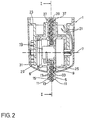
- die Leuchtenhalterung der Fig. 1 im Schnitt entlang einer dort dargestellten Linie II-II,
- Fig. 3
- eine Leuchtenhalterung gemäß einer zweiten Ausführungsform der vorliegenden Erfindung in Draufsicht von der Seite, und
- Fig. 4
- die Leuchtenhalterung der Fig. 3 im Schnitt entlang einer dort dargestellten Linie IV-IV.
- Fig. 1
- a lamp holder according to a first embodiment of the present invention in section,
- Fig. 2
- 1 in section along a line II-II shown there,
- Fig. 3
- a lamp holder according to a second embodiment of the present invention in plan view from the side, and
- Fig. 4
- 3 in section along a line IV-IV shown there.
Die Fig. 1 und 2 zeigen eine Leuchtenhalterung 1 zur Montage an einer Zimmerdecke
3. Die Leuchtenhalterung 1 umfaßt eine Wickeltrommel 5 mit einer im an
der Decke 3 montierten Zustand horizontal sich erstreckende Drehachse 7, einen
Trommelmantel 9 und zwei den Trommelmantel axial begrenzende Trommelscheiben
11. Auf die Wickeltrommel 5 ist ein Stromkabel 13 aufgewickelt, welches
zwei von einem PVC-Mantel 15 umgeben und separat isolierte Stromzuführungsleitungen
17 aufweist. Das Stromkabel 13 genügt der deutschen Norm DIN
VDE 0281-5 und trägt das Bauartkurzzeichen H03VV-F-2x0,75. Das Stromkabel
13 ist an sich flexibel, allerdings widersetzt es sich einer Änderung seiner
Krümmung mit einer gewissen Zähigkeit, welche insbesondere bei niederen
Temperaturen, bei welchem das PVC-Material weniger geschmeidig ist, erhöht
ist. Um diese Zähigkeit wenigstens etwas zu vermindern, haften die Stromzuführungsleitungen
17 nicht an dem PVC-Mantel 15. 1 and 2 show a lamp holder 1 for mounting on a
Die Leuchtenhalterung 1 umfaßt ferner eine Schleifkontakteinrichtung 19, um
die Stromzuführungsleitungen 17 des Stromkabels 13 mit Leitungen 21 zum Anschluß
an einen Deckenstromauslaß zu verbinden.The lamp holder 1 further comprises a sliding
Die Wickeltrommel 5 ist an einer Trommelhalterung 23 drehbar gelagert, welche
mit der Decke 3 zu verschrauben ist. Zwischen der Trommelhalterung 23 und der
Wickeltrommel 5 ist eine Spiralfeder 25 eingeschaltet, welche die Wickeltrommel
5 bezüglich der Trommelhalterung 23 in eine durch einen Pfeil 27 gekennzeichnete
Aufwickelrichtung antreibt. Die Federkraft ist hierbei auf das Leuchtengewicht
abgestimmt, wobei eine Freilaufeinrichtung 6 vorgesehen ist, die mit einer
Reibeinrichtung 29 derart gekoppelt ist, daß diese lediglich in Abwickelrichtung
wirksam ist und das Abwickeln des Stromkabels 13 von der Wickeltrommel 5
aufgrund des Eigengewichts der Leuchte verhindert ist.The winding
An der Trommelhalterung 23 sind an deren oberem Bereich ferner zwei Führungswandungen
37 ausgebildet, von denen sich eine jede in radialer Verlängerung
einer der Trommelscheiben 11 erstreckt. Zwischen diesen Führungswandungen
37 ist bei vollständig auf der Wickeltrommel 5 aufgewickeltem Stromkabel
13 eine Lage 39 des Stromkabels 13 über einen Teilumfang der Wickeltrommel
5 aufgenommen, so daß ein über dem Radius der Trommelscheiben 11 hinausgehender
Bereich zum Aufwickeln des Stromkabels 13 ausgenutzt werden
kann, ohne daß das Stromkabel 13 von der Wickeltrommel 5 gleitet.On the upper part of the
Die Trommelhalterung 23 und wesentliche Teile der Wickeltrommel 5 sind durch
eine auf die Trommelhalterung 23 aufgestecke Abdeckung 31 gegenüber Blicken
des Betrachters verdeckt. Die Abdeckung 31 weist einen sich in Umfangsrichtung
der Wickeltrommel 5 erstreckenden Schlitz 33 auf, den die Trommelscheiben 11
durchsetzen. Hierbei weisen die Längsflanken des Schlitzes 33 einen lediglich
geringfügigen Abstand zu den Außenflächen der Trommelscheiben 11 auf, und in
Längsrichtung ist der Schlitz 33 derart bemessen, daß er einen geringfügigen
Abstand zu den Stirnflächen der Trommelscheiben 11 aufweist. Das Stromkabel
13 durchsetzt den Schlitz 33, wobei es beidseitig durch die Trommelscheibe 11
geführt ist. Wenn sich das Stromkabel 13, wie in Fig. 1 dargestellt senkrecht
nach unten erstreckt, berührt es die Abdeckung 31 nicht.The
Diese einfache Bereitstellung der Führungsfunktion zum geordneten Aufwickeln
des Stromkabels 13 auf die Wickeltrommel 5 ermöglicht eine weitgehend vernachlässigbare
Reibung zwischen dem Stromkabel 13 und den Komponenten der
Leuchtenhalterung 1, so daß eine Spiralfeder 25 mit vergleichsweise geringer Federkraft
eingesetzt werden kann, was wiederum einen Schritt hin zu geringen
Leuchtengewichten erschließt.This simple provision of the management function for orderly winding
of the
Im folgenden wird eine Variante der in den Fig. 1 und 2 dargestellten Leuchtenhalterung erläutert. Hinsichtlich ihres Aufbaus und ihrer Funktion einander entsprechende Komponenten sind mit den Bezugsziffern aus den Fig. 1 und 2 bezeichnet, jedoch zur Unterscheidung mit einem Buchstaben versehen. Zur Erläuterung wird auf die gesamte vorangehende Beschreibung Bezug genommen.The following is a variant of the lamp holder shown in FIGS. 1 and 2 explained. In terms of their structure and their function corresponding components are identified by the reference numerals from FIGS. 1 and 2 labeled, but with a letter to distinguish it. In order to explain reference is made to the entire foregoing description.
Die in Fig. 3 und 4 dargestellte Leuchtenhalterung 1a unterscheidet sich von der
vorangehend beschriebenen Ausführungsform lediglich in der Gestaltung des
Schlitzes 33a der Abdeckung 31a. Der Schlitz 33a ist nämlich im Vergleich zu
der vorangehend beschriebenen Ausführungsform in seiner Längsrichtung in
Aufwickelrichtung 27a der Wickeltrommel 5a und insbesondere nach oben bis zu
einem näher an der Decke 3a liegenden Schlitzende 35 verlängert.The
In Fig. 4 ist der Verlauf des Stromkabels 13a während des Aufwickelvorgangs
dargestellt. Das Stromkabel 13 ist zwar flexibel, setzt jedoch einer Änderung seines
Krümmungsradius einen gewissen Widerstand in Form einer Zähigkeit entgegen,
so daß es sich beim Aufwickeln nicht tangential von der Wickeltrommel
weg nach senkrecht unten erstreckt, sondern in etwa den in der Figur 4 dargestellten
gekrümmten Verlauf aufweist. Indem sich der Schlitz 33a in Aufwickelrichtung
27a der Trommel bis zu seinem Schlitzende 35 erstreckt, kann das
Stromkabel 13a die von ihm bevorzugte gekrümmte Gestalt einnehmen, ohne in
Berührung mit der Abdeckung 31a zu gelangen. Hierdurch liegt auch während
eines schnellen Aufwickelvorganges eine im wesentlichen vernachlässigbare Reibung
zwischen den Komponenten der Leuchtenhalterung 1a und dem Stromkabel
13a vor.In Fig. 4 is the course of the
Die Lage des Schlitzendes 35 an der Abdeckung 31 ist dabei so gewählt, daß sich
ein tangential und geradlinig von der vollen Wickeltrommel 5a weg erstreckendes
Stromkabel 13a' ohne Berührung mit dem Schlitzende 35, ausgehend von einem
Punkt P von der Wickeltrommel 5a weg erstreckt, welcher in Aufwickelrichtung
27 um einen Winkel α von etwa 80° aus einer Horizontalen 38 versetzt ist. Eine
solche Bemessung des Schlitzes 33a ermöglicht auch bei vergleichsweise niedrigen
Raumtemperaturen und einer damit einhergehenden geringen Flexibilität
des Stromkabels 13a, ein gutes Funktionieren der Leuchtenhalterung 1a.The position of the
Die vorangehend beschriebene Anordnung kann neben der Halterung für eine Leuchte auch zur Halterung eines beliebigen anderen elektrischen Gerätes eingesetzt werden. Neben dem Einsatz eines PVC-Schlauchkabels sind auch andere Stromkabel einsetzbar, wie z. B. Silicon oder Gummikabel.The arrangement described above can in addition to the holder for a Luminaire also used to hold any other electrical device become. In addition to using a PVC hose cable, there are also others Power cables can be used, such as B. silicone or rubber cable.
Claims (9)
die Trommelscheiben (11) die Abdeckung (31) derart durchsetzen, daß die Austrittsausnehmung (33) von der Abdeckung (31) und von den Trommelscheiben (11) begrenzt ist.Arrangement for the height-adjustable hanging bracket of an electrically operated device, in particular a pendant lamp, comprising:
the drum disks (11) penetrate the cover (31) such that the outlet recess (33) is delimited by the cover (31) and by the drum disks (11).
Applications Claiming Priority (2)
| Application Number | Priority Date | Filing Date | Title |
|---|---|---|---|
| DE19853228 | 1998-11-18 | ||
| DE19853228A DE19853228C2 (en) | 1998-11-18 | 1998-11-18 | Arrangement for height-adjustable hanging bracket of an electrically operated device |
Publications (3)
| Publication Number | Publication Date |
|---|---|
| EP1002991A2 true EP1002991A2 (en) | 2000-05-24 |
| EP1002991A3 EP1002991A3 (en) | 2001-09-26 |
| EP1002991B1 EP1002991B1 (en) | 2003-04-16 |
Family
ID=7888242
Family Applications (1)
| Application Number | Title | Priority Date | Filing Date |
|---|---|---|---|
| EP99120780A Expired - Lifetime EP1002991B1 (en) | 1998-11-18 | 1999-10-20 | Apparatus for the height-adjustable suspension of an electric device |
Country Status (3)
| Country | Link |
|---|---|
| EP (1) | EP1002991B1 (en) |
| AT (1) | ATE237783T1 (en) |
| DE (2) | DE19853228C2 (en) |
Cited By (2)
| Publication number | Priority date | Publication date | Assignee | Title |
|---|---|---|---|---|
| EP1615847A2 (en) * | 2003-04-07 | 2006-01-18 | Michael Blair Hopper | Tool support |
| WO2020223746A1 (en) * | 2019-05-08 | 2020-11-12 | Prolicht Gmbh | Lighting device |
Citations (1)
| Publication number | Priority date | Publication date | Assignee | Title |
|---|---|---|---|---|
| DE4411990A1 (en) | 1994-04-08 | 1995-10-12 | Andreas Wilke | Pendant lamp with traction drive |
Family Cites Families (3)
| Publication number | Priority date | Publication date | Assignee | Title |
|---|---|---|---|---|
| US1471384A (en) * | 1921-08-23 | 1923-10-23 | Claussen Martin | Electric lamp |
| US3002086A (en) * | 1959-04-25 | 1961-09-26 | Reeber Karl | Pulling-lamp-fixture |
| DE4002372A1 (en) * | 1989-09-01 | 1991-03-07 | Hoffmeister Leuchten Kg | Rotatable and pivotable electric lamp for room lighting - is supplied with current via cable executing one or more turns within hub of rotary drum |
-
1998
- 1998-11-18 DE DE19853228A patent/DE19853228C2/en not_active Expired - Fee Related
-
1999
- 1999-10-20 AT AT99120780T patent/ATE237783T1/en not_active IP Right Cessation
- 1999-10-20 EP EP99120780A patent/EP1002991B1/en not_active Expired - Lifetime
- 1999-10-20 DE DE59905055T patent/DE59905055D1/en not_active Expired - Lifetime
Patent Citations (1)
| Publication number | Priority date | Publication date | Assignee | Title |
|---|---|---|---|---|
| DE4411990A1 (en) | 1994-04-08 | 1995-10-12 | Andreas Wilke | Pendant lamp with traction drive |
Cited By (3)
| Publication number | Priority date | Publication date | Assignee | Title |
|---|---|---|---|---|
| EP1615847A2 (en) * | 2003-04-07 | 2006-01-18 | Michael Blair Hopper | Tool support |
| EP1615847A4 (en) * | 2003-04-07 | 2006-09-20 | Michael Blair Hopper | Tool support |
| WO2020223746A1 (en) * | 2019-05-08 | 2020-11-12 | Prolicht Gmbh | Lighting device |
Also Published As
| Publication number | Publication date |
|---|---|
| DE59905055D1 (en) | 2003-05-22 |
| EP1002991B1 (en) | 2003-04-16 |
| EP1002991A3 (en) | 2001-09-26 |
| ATE237783T1 (en) | 2003-05-15 |
| DE19853228C2 (en) | 2001-12-13 |
| DE19853228A1 (en) | 2000-06-08 |
Similar Documents
| Publication | Publication Date | Title |
|---|---|---|
| DE602004009557T2 (en) | WINDING CABLE HASP FOR USE WITH ELECTRIC FLAT CABLE | |
| DE69838710T2 (en) | RETRACTABLE DRUM WITH CHANNELS SEALED LOCKING MECHANISM | |
| DE102008034770B4 (en) | Remote-operated cable coupling for vehicles | |
| DE3119532A1 (en) | WINDOW CRANK DEVICE WITH BENDING SCREW | |
| DE112014001271B4 (en) | Flachkabelaufrollgerät | |
| EP0827596A1 (en) | Hood-type connector | |
| EP0475017B1 (en) | Controlling cable adjusting device | |
| EP2634878A1 (en) | Table connection field | |
| DE4332300C1 (en) | Hair dryer with a cable winding device | |
| EP1002991B1 (en) | Apparatus for the height-adjustable suspension of an electric device | |
| DE3540012A1 (en) | DEVICE FOR WINDING A CABLE | |
| EP3217061B1 (en) | Suspension device for a lighting unit | |
| EP0163025B1 (en) | Storage device for a connection cable of a central board mains supply installation | |
| DE19858874B4 (en) | Electric rotary switch | |
| DE3220646A1 (en) | DEVICE FOR RECORDING, HANDLING AND FILLING COILS FOR WIRE, CABLES AND THE LIKE AND DEVICE FOR RECEIVING AND ROTATING SUCH REELS | |
| DE2548131A1 (en) | CABLE REEL | |
| EP0676586B1 (en) | Pendant lighting fixture with carrier cable driving mechanism | |
| DE3441790C2 (en) | ||
| EP2072441A2 (en) | Cable drum | |
| DE3302529A1 (en) | Winding shaft for blinds | |
| DE3210793A1 (en) | Device for winding up a cable | |
| DE3219570A1 (en) | Strap winder for roller blinds, shutters, awnings or the like | |
| EP0037596B1 (en) | Drive mechanism for flexible record carriers | |
| DE202013100618U1 (en) | Retractor for curtains | |
| EP1312858A2 (en) | Winding device |
Legal Events
| Date | Code | Title | Description |
|---|---|---|---|
| PUAI | Public reference made under article 153(3) epc to a published international application that has entered the european phase |
Free format text: ORIGINAL CODE: 0009012 |
|
| AK | Designated contracting states |
Kind code of ref document: A2 Designated state(s): AT BE CH CY DE DK ES FI FR GB GR IE IT LI LU MC NL PT SE |
|
| AX | Request for extension of the european patent |
Free format text: AL;LT;LV;MK;RO;SI |
|
| PUAL | Search report despatched |
Free format text: ORIGINAL CODE: 0009013 |
|
| AK | Designated contracting states |
Kind code of ref document: A3 Designated state(s): AT BE CH CY DE DK ES FI FR GB GR IE IT LI LU MC NL PT SE |
|
| AX | Request for extension of the european patent |
Free format text: AL;LT;LV;MK;RO;SI |
|
| 17P | Request for examination filed |
Effective date: 20020326 |
|
| AKX | Designation fees paid |
Free format text: AT BE CH CY DE DK ES FI FR GB GR IE IT LI LU MC NL PT SE |
|
| GRAG | Despatch of communication of intention to grant |
Free format text: ORIGINAL CODE: EPIDOS AGRA |
|
| 17Q | First examination report despatched |
Effective date: 20020625 |
|
| GRAG | Despatch of communication of intention to grant |
Free format text: ORIGINAL CODE: EPIDOS AGRA |
|
| GRAH | Despatch of communication of intention to grant a patent |
Free format text: ORIGINAL CODE: EPIDOS IGRA |
|
| GRAH | Despatch of communication of intention to grant a patent |
Free format text: ORIGINAL CODE: EPIDOS IGRA |
|
| GRAA | (expected) grant |
Free format text: ORIGINAL CODE: 0009210 |
|
| AK | Designated contracting states |
Designated state(s): AT BE CH CY DE DK ES FI FR GB GR IE IT LI LU MC NL PT SE |
|
| PG25 | Lapsed in a contracting state [announced via postgrant information from national office to epo] |
Ref country code: NL Free format text: LAPSE BECAUSE OF FAILURE TO SUBMIT A TRANSLATION OF THE DESCRIPTION OR TO PAY THE FEE WITHIN THE PRESCRIBED TIME-LIMIT Effective date: 20030416 Ref country code: IT Free format text: LAPSE BECAUSE OF FAILURE TO SUBMIT A TRANSLATION OF THE DESCRIPTION OR TO PAY THE FEE WITHIN THE PRE;WARNING: LAPSES OF ITALIAN PATENTS WITH EFFECTIVE DATE BEFORE 2007 MAY HAVE OCCURRED AT ANY TIME BEFORE 2007. THE CORRECT EFFECTIVE DATE MAY BE DIFFERENT FROM THE ONE RECORDED.SCRIBED TIME-LIMIT Effective date: 20030416 Ref country code: IE Free format text: LAPSE BECAUSE OF NON-PAYMENT OF DUE FEES Effective date: 20030416 Ref country code: GB Free format text: LAPSE BECAUSE OF FAILURE TO SUBMIT A TRANSLATION OF THE DESCRIPTION OR TO PAY THE FEE WITHIN THE PRESCRIBED TIME-LIMIT Effective date: 20030416 Ref country code: FR Free format text: LAPSE BECAUSE OF FAILURE TO SUBMIT A TRANSLATION OF THE DESCRIPTION OR TO PAY THE FEE WITHIN THE PRESCRIBED TIME-LIMIT Effective date: 20030416 Ref country code: FI Free format text: LAPSE BECAUSE OF FAILURE TO SUBMIT A TRANSLATION OF THE DESCRIPTION OR TO PAY THE FEE WITHIN THE PRESCRIBED TIME-LIMIT Effective date: 20030416 |
|
| REG | Reference to a national code |
Ref country code: GB Ref legal event code: FG4D Free format text: NOT ENGLISH |
|
| REG | Reference to a national code |
Ref country code: CH Ref legal event code: EP |
|
| REF | Corresponds to: |
Ref document number: 59905055 Country of ref document: DE Date of ref document: 20030522 Kind code of ref document: P |
|
| REG | Reference to a national code |
Ref country code: IE Ref legal event code: FG4D Free format text: GERMAN |
|
| PG25 | Lapsed in a contracting state [announced via postgrant information from national office to epo] |
Ref country code: PT Free format text: LAPSE BECAUSE OF FAILURE TO SUBMIT A TRANSLATION OF THE DESCRIPTION OR TO PAY THE FEE WITHIN THE PRESCRIBED TIME-LIMIT Effective date: 20030716 Ref country code: GR Free format text: LAPSE BECAUSE OF FAILURE TO SUBMIT A TRANSLATION OF THE DESCRIPTION OR TO PAY THE FEE WITHIN THE PRESCRIBED TIME-LIMIT Effective date: 20030716 Ref country code: DK Free format text: LAPSE BECAUSE OF FAILURE TO SUBMIT A TRANSLATION OF THE DESCRIPTION OR TO PAY THE FEE WITHIN THE PRESCRIBED TIME-LIMIT Effective date: 20030716 |
|
| REG | Reference to a national code |
Ref country code: SE Ref legal event code: TRGR |
|
| NLV1 | Nl: lapsed or annulled due to failure to fulfill the requirements of art. 29p and 29m of the patents act | ||
| GBV | Gb: ep patent (uk) treated as always having been void in accordance with gb section 77(7)/1977 [no translation filed] |
Effective date: 20030416 |
|
| PG25 | Lapsed in a contracting state [announced via postgrant information from national office to epo] |
Ref country code: LU Free format text: LAPSE BECAUSE OF NON-PAYMENT OF DUE FEES Effective date: 20031020 Ref country code: CY Free format text: LAPSE BECAUSE OF FAILURE TO SUBMIT A TRANSLATION OF THE DESCRIPTION OR TO PAY THE FEE WITHIN THE PRESCRIBED TIME-LIMIT Effective date: 20031020 Ref country code: AT Free format text: LAPSE BECAUSE OF NON-PAYMENT OF DUE FEES Effective date: 20031020 |
|
| PG25 | Lapsed in a contracting state [announced via postgrant information from national office to epo] |
Ref country code: ES Free format text: LAPSE BECAUSE OF FAILURE TO SUBMIT A TRANSLATION OF THE DESCRIPTION OR TO PAY THE FEE WITHIN THE PRESCRIBED TIME-LIMIT Effective date: 20031030 |
|
| PG25 | Lapsed in a contracting state [announced via postgrant information from national office to epo] |
Ref country code: MC Free format text: LAPSE BECAUSE OF NON-PAYMENT OF DUE FEES Effective date: 20031031 Ref country code: LI Free format text: LAPSE BECAUSE OF NON-PAYMENT OF DUE FEES Effective date: 20031031 Ref country code: CH Free format text: LAPSE BECAUSE OF NON-PAYMENT OF DUE FEES Effective date: 20031031 Ref country code: BE Free format text: LAPSE BECAUSE OF NON-PAYMENT OF DUE FEES Effective date: 20031031 |
|
| REG | Reference to a national code |
Ref country code: IE Ref legal event code: FD4D Ref document number: 1002991E Country of ref document: IE |
|
| PLBE | No opposition filed within time limit |
Free format text: ORIGINAL CODE: 0009261 |
|
| STAA | Information on the status of an ep patent application or granted ep patent |
Free format text: STATUS: NO OPPOSITION FILED WITHIN TIME LIMIT |
|
| 26N | No opposition filed |
Effective date: 20040119 |
|
| EN | Fr: translation not filed | ||
| BERE | Be: lapsed |
Owner name: *WILKE ANDREAS Effective date: 20031031 |
|
| REG | Reference to a national code |
Ref country code: CH Ref legal event code: PL |
|
| PGFP | Annual fee paid to national office [announced via postgrant information from national office to epo] |
Ref country code: SE Payment date: 20061017 Year of fee payment: 8 |
|
| EUG | Se: european patent has lapsed | ||
| PG25 | Lapsed in a contracting state [announced via postgrant information from national office to epo] |
Ref country code: SE Free format text: LAPSE BECAUSE OF NON-PAYMENT OF DUE FEES Effective date: 20071021 |
|
| PGFP | Annual fee paid to national office [announced via postgrant information from national office to epo] |
Ref country code: DE Payment date: 20101031 Year of fee payment: 12 |
|
| PG25 | Lapsed in a contracting state [announced via postgrant information from national office to epo] |
Ref country code: DE Free format text: LAPSE BECAUSE OF NON-PAYMENT OF DUE FEES Effective date: 20130501 |
|
| REG | Reference to a national code |
Ref country code: DE Ref legal event code: R119 Ref document number: 59905055 Country of ref document: DE Effective date: 20120501 Ref country code: DE Ref legal event code: R119 Ref document number: 59905055 Country of ref document: DE Effective date: 20130501 |
|
| PG25 | Lapsed in a contracting state [announced via postgrant information from national office to epo] |
Ref country code: DE Free format text: LAPSE BECAUSE OF NON-PAYMENT OF DUE FEES Effective date: 20120501 |