EP1000343B1 - Allergen detector system and method - Google Patents
Allergen detector system and method Download PDFInfo
- Publication number
- EP1000343B1 EP1000343B1 EP98933119A EP98933119A EP1000343B1 EP 1000343 B1 EP1000343 B1 EP 1000343B1 EP 98933119 A EP98933119 A EP 98933119A EP 98933119 A EP98933119 A EP 98933119A EP 1000343 B1 EP1000343 B1 EP 1000343B1
- Authority
- EP
- European Patent Office
- Prior art keywords
- light
- predetermined
- particles
- allergen
- air
- Prior art date
- Legal status (The legal status is an assumption and is not a legal conclusion. Google has not performed a legal analysis and makes no representation as to the accuracy of the status listed.)
- Expired - Lifetime
Links
- 239000013566 allergen Substances 0.000 title claims abstract description 45
- 238000000034 method Methods 0.000 title claims description 8
- 239000002245 particle Substances 0.000 claims abstract description 66
- 230000000903 blocking effect Effects 0.000 claims abstract description 40
- 238000001914 filtration Methods 0.000 claims abstract description 6
- 230000007613 environmental effect Effects 0.000 claims description 8
- 230000003287 optical effect Effects 0.000 claims description 5
- 239000000463 material Substances 0.000 claims description 4
- 230000003213 activating effect Effects 0.000 claims 1
- 238000004378 air conditioning Methods 0.000 abstract 1
- 230000001419 dependent effect Effects 0.000 description 5
- 238000001514 detection method Methods 0.000 description 4
- 238000010586 diagram Methods 0.000 description 4
- 238000012986 modification Methods 0.000 description 3
- 230000004048 modification Effects 0.000 description 3
- 230000002009 allergenic effect Effects 0.000 description 2
- 229940079593 drug Drugs 0.000 description 2
- 239000003814 drug Substances 0.000 description 2
- 238000005259 measurement Methods 0.000 description 2
- 239000003973 paint Substances 0.000 description 2
- 230000035945 sensitivity Effects 0.000 description 2
- 208000024891 symptom Diseases 0.000 description 2
- 206010002198 Anaphylactic reaction Diseases 0.000 description 1
- 206010011224 Cough Diseases 0.000 description 1
- 208000010201 Exanthema Diseases 0.000 description 1
- 206010020751 Hypersensitivity Diseases 0.000 description 1
- 239000013572 airborne allergen Substances 0.000 description 1
- 230000000172 allergic effect Effects 0.000 description 1
- 230000007815 allergy Effects 0.000 description 1
- 230000036783 anaphylactic response Effects 0.000 description 1
- 208000003455 anaphylaxis Diseases 0.000 description 1
- 238000000149 argon plasma sintering Methods 0.000 description 1
- 208000006673 asthma Diseases 0.000 description 1
- 208000010668 atopic eczema Diseases 0.000 description 1
- 238000004140 cleaning Methods 0.000 description 1
- 239000000428 dust Substances 0.000 description 1
- 201000005884 exanthem Diseases 0.000 description 1
- 239000005357 flat glass Substances 0.000 description 1
- 235000015220 hamburgers Nutrition 0.000 description 1
- 238000004519 manufacturing process Methods 0.000 description 1
- 239000002184 metal Substances 0.000 description 1
- 206010037844 rash Diseases 0.000 description 1
- 230000001105 regulatory effect Effects 0.000 description 1
- 238000004904 shortening Methods 0.000 description 1
- 231100000046 skin rash Toxicity 0.000 description 1
- 206010041232 sneezing Diseases 0.000 description 1
- 238000009423 ventilation Methods 0.000 description 1
- 230000000007 visual effect Effects 0.000 description 1
Images

Classifications
-
- G—PHYSICS
- G01—MEASURING; TESTING
- G01N—INVESTIGATING OR ANALYSING MATERIALS BY DETERMINING THEIR CHEMICAL OR PHYSICAL PROPERTIES
- G01N21/00—Investigating or analysing materials by the use of optical means, i.e. using sub-millimetre waves, infrared, visible or ultraviolet light
- G01N21/17—Systems in which incident light is modified in accordance with the properties of the material investigated
- G01N21/47—Scattering, i.e. diffuse reflection
- G01N21/49—Scattering, i.e. diffuse reflection within a body or fluid
- G01N21/53—Scattering, i.e. diffuse reflection within a body or fluid within a flowing fluid, e.g. smoke
-
- G—PHYSICS
- G01—MEASURING; TESTING
- G01N—INVESTIGATING OR ANALYSING MATERIALS BY DETERMINING THEIR CHEMICAL OR PHYSICAL PROPERTIES
- G01N15/00—Investigating characteristics of particles; Investigating permeability, pore-volume or surface-area of porous materials
- G01N15/02—Investigating particle size or size distribution
- G01N15/0205—Investigating particle size or size distribution by optical means
Definitions
- the present invention is directed to an apparatus and a method for detecting airborne allergen particles and for providing an alarm or operating a filtering system if the detected amount of allergen particles is above a predetermined level.
- a control circuit may be connected to the detector for generating an alarm output signal if the detector output is above a predetermined level.
- the alarm output signal may be used to activate an audible or visual alarm device, or to turn on a filtration and ventilation system including HEPA (RTM) or allergen particle filters.
- the filtration system may be turned off as soon as the detected allergen particles have returned to a safe level.
- the apparatus may be relatively small, and may be conveniently designed for wall mounting.
- the beam blocking assembly preferably comprises a disc of light blocking material centered on the optical axis and of predetermined diameter to block all unscattered light and light scattered at angles below a predetermined minimum angle which is scattered by particles larger than 50 ⁇ m, and an annular ring of light blocking material having an inner diameter corresponding to the predetermined maximum scattering angle, such that light scattered by particles smaller than 5 ⁇ m is blocked.
- the focusing lens is arranged to focus the light beam onto the central, beam blocking disc.
- the light source is a light emitting diode- (LED).
- LED light emitting diode-
- the focusing lens and beam blocker arrangement allow an inexpensive LED to be used as the light source, without requiring any complex collimator arrangement.
- the diameter of the beam blocker disc is sufficient to block all unscattered light from the LED. In other words, it has a diameter slightly larger than the focused spot diameter of the focusing lens. If no allergen-size particles are present, all light will be blocked by the beam blocker.
- This system and method readily discriminates between allergen-size particles in the 5 to 50 micron range and larger, non-allergenic particles so as to produce an accurate indication of the allergen particle levels in a room or enclosed area.
- the level at which the alarm signal is produced is adjustable.
- the apparatus can be readily connected to turn on auxiliary air cleaning appliances or filters such as HEPA (RTM) filters.
- FIG. 1 of the drawings illustrates an allergen particle detector apparatus according to a first embodiment of the present invention.
- the apparatus will be enclosed in a suitable outer housing shaped to provide a passageway or air gap 10 for exposure to environmental air in order to test an air sample for allergen-size particles, as in our US-A-6 087 947.
- a laser beam is directed from laser diode or LED 12 across the air sample 10 towards a beam blocking device 14 on the opposite side of the air gap.
- the device 14 comprises a transparent circular flat glass plate 15 with an opaque portion or disc 16 at the center of the plate. Portion 16 may be produced by black paint, or a black plastic or metal insert at the center of the plate.
- a focusing lens 18 in front of LED 12 is arranged to focus the laser output beam onto the beam blocking disc 16.
- the actual dimensions of the opaque blocking portion will be dependent on the cross-sectional shape and dimensions of the focused output beam of laser diode 12, and the particle size range to be detected by the apparatus.
- the LED may emit infrared light (0.8-1.0 ⁇ m (micron)) or visible light. In one embodiment of the invention an LED emitting at the wavelength of 670 nm. was used.
- the majority of allergen particles to which individuals may be sensitive are in the size range of 5 to 50 ⁇ m (microns), although a small quantity of allergen particles may be found at sizes from 0.5 to 5 ⁇ m (microns) and from 50 to 500 ⁇ m (microns). Thus, substantially all allergen particles will be found in the size range of 0.5 to 500 ⁇ m (microns), with the maximum number being in the range of 5 to 50 ⁇ m (microns). Therefore, the apparatus is designed to detect particles in the range of 5 to 50 ⁇ m (microns), since the majority of allergens will be in this size range.
- the angle at which light is scattered by a particle will be dependent on the wavelength of the light and the size of the particle. Airborne particles of different sizes have quite different light scattering properties. Larger particles will scatter light at smaller angles. For a red to infrared light source in the wavelength range of 0.6 to 1.0 ⁇ m (micron), the smallest scattering angle for a particle size range of 0.5 to 50 ⁇ m (microns) is about 4° to 5° (see Electromagnetic Scattering , R.L. Rowell and R.S. Stein, ed., p. 140, Gordon and Breach 1965).
- the radius of the central blocking portion should be L * tan (5°), in order to block light scattered at angles less than 5°, i.e. light scattered by particles larger than 50 ⁇ m (microns).
- the blocking device can therefore be arranged to block all light scattered by particles of size greater than 50 ⁇ m (microns).
- Lens 20 is positioned behind blocking device 14 in order to focus light transmitted by the device 14 onto a detector 22.
- the output of detector 22 is connected via amplifier 24 to a threshold and timer circuit 26. If the output of detector 22 is bove a predetermined threshold, relay switch 28 is closed to connect power supply 30 to the air filter 32, which may be any suitable HEPA (RTM) filter.
- the power supply is also connected via adapter 34 to the laser diode.
- the beam blocking device 14 also includes an annular ring 42 of light blocking material placed in front of disc 15. Alternatively, the disc itself may be painted black around a corresponding annular area.
- An annular ring through which light will be transmitted is defined between beam blocking disc 16 and annular ring 42.
- the light transmitting annular ring will have a predetermined inner diameter d1 corresponding to the diameter of the center disc 16, and a predetermined outer diameter d2 corresponding to the inner diameter of ring 42.
- the dimensions d1 and d2 will be determined based on the particle size range to be detected which is 5-50 ⁇ m according to the present invention. The majority of allergen particles are in the size range of 5 to 50 ⁇ m (microns).
- the diameter d1 is therefore determined from the relationship L * tan(50).
- the diameter d2 is determined from L * tan 8°), where L is the distance of the discriminator 118 from the sensitive region or air sample. With these dimensions, the device 118 will transmit only light scattered in the range of 5° to 8° by particles in the range from 5 to 50 ⁇ m (microns).
- the use of the focusing lens 18 in conjunction with blocking disc 16 allows a simple and inexpensive laser light emitting diode or LED 12 to be used as the light source, instead of other, more expensive types of laser emitters.
- the focusing lens avoids the need to use a complex collimating arrangement for collimating the diffuse output beam of LED 12.
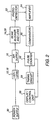
- Figure 2 illustrates a modified output circuit for the allergen detector system, which provides, greater sensitivity in situations where the actual number of allergens present in the air is low.
- the detector apparatus is otherwise identical to that of Figure 1, and like reference numerals are used for like parts as appropriate.
- the sample area or air gap 10 is of relatively small volume, of the order of a few cubic centimeters.
- the detector will register counts only in a discrete manner.
- signal pulses from detector 22 are connected to amplifier 24.
- the amplified pulse output is connected to comparator 50 to make a regulated pulse.
- the pulse output of comparator 50 is counted by pulse counter 52.
- a timing circuit 54 resets the pulse counter at predetermined intervals, for example every 30 seconds. Whenever there is an allergen particle in air gap 10, the scattered light will trigger the photodetector and subsequently the amplifier and comparator will produce an output pulse. This pulse represents detection of a single allergen particle.
- the pulse counter 52 registers all pulses in a certain period of time, determined by timing circuit 54. The total number of pulses registered is displayed on light emitting diode display unit 56. After each measurement period, say 30 seconds, the counter is reset to zero counts and begins to accumulate counts again.
- the counter trigger level is preferably adjustable by the user, so that different sensitivity levels can be detected as desired by the user.
- This arrangement permits measurement of allergen density in a low range, and is particularly useful with a stand-alone allergen detector unit, where no additional air moving apparatus is used. With such an arrangement, allergen particles will drift randomly into the air gap, and there may be periods during which no allergen particles are detected when the allergen density in the air is low. By accumulating particle counts over an extended period of time, lower allergen particle density levels may be detected. Any standard, off-the-shelf pulse counter may be used, such as a 7492 counter.
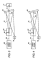
- Figure 3 of the drawings illustrates a modified allergen detector apparatus according to a second embodiment of the invention.
- the apparatus will be enclosed in a suitable housing (not illustrated) shaped to provide a passageway or air gap 60 for exposure to environmental air, in order to test an air sample within air gap 60 to detect the presence of allergen-size particles 62, as described in US-A-6 087 947 referred to above.
- a laser beam 64 is directed from laser diode 66 through the air sample in gap 60.
- a reflecting concave mirror 68 with a central opening 70 of predetermined dimensions is positioned on the opposite side of air gap 60.
- a lens 18 (not illustrated) may be positioned between diode 66 and air gap 60 as in the previous embodiment in order to focus the laser output beam onto central opening 70 in the concave mirror, which acts in the same way as the beam blocking disc of the previous embodiment.
- the actual dimensions of the central opening 70 will be dependent on the cross-sectional shape and dimensions of the focused laser beam and the particle size range to be detected by the apparatus, as in the previous embodiment.
- Figure 4 illustrates a modification which is similar to the embodiment of Figure 3 with the exception that the central opening 70 in concave mirror 68 is replaced by a black beam blocker 72 which may be provided by black paint or a black disc applied to the mirror. All other parts of the embodiment of Figure 4 are identical to that of Figure 3, and like reference numerals have been used for like parts, as appropriate.
- the unscattered light beam 74 is eliminated, either by leaking through the central opening 70 in the mirror in Figure 3 to a beam dump 71, or by blocking it with beam blocker 72 at the center of the mirror, as in Figure 4.
- allergen particles in the air gap 60 will scatter the light beam, and the scattered light beam 75 will be reflected from the mirror 68 onto a photodetector 76 placed alongside the laser diode.
- the size of the central opening or beam blocker is preferably sufficient to block or receive unscattered portions of the light beam and portions scattered at angles below a predetermined minimum angle as described above in connection with the preceding embodiments, while the outer diameter of the mirror is selected such that light scattered above a predetermined maximum angle passes the mirror without reflection.
- only light scattered in the desired angular range corresponding to allergen-size particles (5-50 ⁇ m) will be redirected along the light path to the detector 76.
- the allergen particle detector of this invention detects only allergen-size particles and eliminates light scattered by particles of sizes outside the allergen size range of 5 to 50 microns (5 x 10 -6 m to 50 x 10 -6 m) .
- the light source is a simple and inexpensive laser light emitting diode, used with a focusing lens to focus the unscattered beam onto a beam blocking disc.
- the allergen detection level may be readily adjusted by the user.
- the apparatus is easy and inexpensive to manufacture, and simple to operate. It provides real time, accurate detection of excessive levels of allergen particles in the air, providing a warning to sensitive individuals who may need medication and also allowing allergen filtering equipment to be activated under such conditions to clean the air.
Landscapes
- Chemical & Material Sciences (AREA)
- General Health & Medical Sciences (AREA)
- Life Sciences & Earth Sciences (AREA)
- Health & Medical Sciences (AREA)
- Analytical Chemistry (AREA)
- Biochemistry (AREA)
- Physics & Mathematics (AREA)
- General Physics & Mathematics (AREA)
- Immunology (AREA)
- Pathology (AREA)
- Dispersion Chemistry (AREA)
- Investigating Or Analysing Materials By Optical Means (AREA)
- Medicines Containing Antibodies Or Antigens For Use As Internal Diagnostic Agents (AREA)
- Investigating Or Analysing Biological Materials (AREA)
Applications Claiming Priority (3)
| Application Number | Priority Date | Filing Date | Title |
|---|---|---|---|
| US887533 | 1997-07-03 | ||
| US08/887,533 US6008729A (en) | 1996-07-11 | 1997-07-03 | Allergen detector system and method |
| PCT/US1998/013837 WO1999001748A1 (en) | 1997-07-03 | 1998-07-02 | Allergen detector system and method |
Publications (2)
| Publication Number | Publication Date |
|---|---|
| EP1000343A1 EP1000343A1 (en) | 2000-05-17 |
| EP1000343B1 true EP1000343B1 (en) | 2003-09-24 |
Family
ID=25391356
Family Applications (1)
| Application Number | Title | Priority Date | Filing Date |
|---|---|---|---|
| EP98933119A Expired - Lifetime EP1000343B1 (en) | 1997-07-03 | 1998-07-02 | Allergen detector system and method |
Country Status (8)
| Country | Link |
|---|---|
| EP (1) | EP1000343B1 (https=) |
| JP (1) | JP2002512698A (https=) |
| CN (1) | CN1128352C (https=) |
| AT (1) | ATE250757T1 (https=) |
| AU (1) | AU8285698A (https=) |
| DE (1) | DE69818480T2 (https=) |
| TW (1) | TW494231B (https=) |
| WO (1) | WO1999001748A1 (https=) |
Families Citing this family (15)
| Publication number | Priority date | Publication date | Assignee | Title |
|---|---|---|---|---|
| NO313728B1 (no) | 1999-04-30 | 2002-11-18 | Ericsson Telefon Ab L M | Tilpassing av tjenester i telekommunikasjonsnett |
| US7053783B2 (en) * | 2002-12-18 | 2006-05-30 | Biovigilant Systems, Inc. | Pathogen detector system and method |
| CN100447555C (zh) * | 2004-04-07 | 2008-12-31 | 中国科学院安徽光学精密机械研究所 | 大气悬浮颗粒物的激光信号实时连续提取方法 |
| EP1784912A4 (en) * | 2004-07-30 | 2012-03-14 | Biovigilant Systems Inc | PATHOGENIC AND PARTICULATE DETECTOR SYSTEM AND METHOD |
| JP2006275998A (ja) * | 2005-03-02 | 2006-10-12 | Kyoto Univ | 光散乱測定装置 |
| ES2419165T3 (es) * | 2007-08-13 | 2013-08-19 | Ndc Infrared Engineering Limited | Método y aparato para la detección electromagnética para su uso en la fabricación de una lámina fibrosa |
| KR20120074558A (ko) * | 2010-12-28 | 2012-07-06 | 삼성전자주식회사 | 미세입자 검출장치 |
| CN102129755B (zh) * | 2011-01-06 | 2012-07-04 | 中国科学技术大学 | 一种基于前向小角度散射的光电感烟探测器 |
| CN104873214B (zh) * | 2015-05-22 | 2018-04-13 | 北京师范大学 | 早期乳腺癌的检测装置 |
| CN109061054A (zh) * | 2018-06-29 | 2018-12-21 | 湖北海纳天鹰科技发展有限公司 | 一种空气中过敏原监测方法和装置 |
| CN109115945A (zh) * | 2018-06-30 | 2019-01-01 | 湖北海纳天鹰科技发展有限公司 | 一种空气中过敏原监测方法和装置 |
| CN109085288A (zh) * | 2018-06-30 | 2018-12-25 | 湖北海纳天鹰科技发展有限公司 | 一种空气中过敏原监测方法和装置 |
| EP3754323B1 (en) * | 2019-06-18 | 2023-08-23 | Plair SA | Automatic spore trap |
| CN115493977B (zh) * | 2021-06-17 | 2025-10-21 | 江苏美的清洁电器股份有限公司 | 一种颗粒检测装置和清洁设备 |
| US20240077412A1 (en) * | 2022-09-06 | 2024-03-07 | Kabushiki Kaisha Toshiba | Optical imaging apparatus, processing apparatus, optical imaging method, and non-transitory storage medium |
Citations (1)
| Publication number | Priority date | Publication date | Assignee | Title |
|---|---|---|---|---|
| WO1998002731A1 (en) * | 1996-07-11 | 1998-01-22 | Sunbeam Products, Inc. | Allergen detector system and method |
Family Cites Families (6)
| Publication number | Priority date | Publication date | Assignee | Title |
|---|---|---|---|---|
| US4286876A (en) * | 1979-01-02 | 1981-09-01 | Coulter Electronics, Inc. | Apparatus and method for measuring scattering of light in particle detection systems |
| DE3000034A1 (de) * | 1979-01-02 | 1980-07-31 | Coulter Electronics | Verfahren und vorrichtung zum messen der richtungsverteilungseigenschaften der von einem teilchen zurueckgestrahlten strahlungsenergie |
| US4830494A (en) * | 1986-07-10 | 1989-05-16 | Kowa Company Ltd. | Method and apparatus for measuring particles in a fluid |
| US5001463A (en) * | 1989-02-21 | 1991-03-19 | Hamburger Robert N | Method and apparatus for detecting airborne allergen particulates |
| US5315115A (en) * | 1992-08-10 | 1994-05-24 | Gerber Hermann E | Optical apparatus and method for sensing particulates |
| US5428964A (en) * | 1994-01-10 | 1995-07-04 | Tec-Way Air Quality Products Inc. | Control for air quality machine |
-
1998
- 1998-07-02 CN CN98806632A patent/CN1128352C/zh not_active Expired - Fee Related
- 1998-07-02 JP JP50740699A patent/JP2002512698A/ja active Pending
- 1998-07-02 EP EP98933119A patent/EP1000343B1/en not_active Expired - Lifetime
- 1998-07-02 WO PCT/US1998/013837 patent/WO1999001748A1/en not_active Ceased
- 1998-07-02 AU AU82856/98A patent/AU8285698A/en not_active Abandoned
- 1998-07-02 DE DE69818480T patent/DE69818480T2/de not_active Expired - Lifetime
- 1998-07-02 AT AT98933119T patent/ATE250757T1/de not_active IP Right Cessation
- 1998-08-11 TW TW087110791A patent/TW494231B/zh not_active IP Right Cessation
Patent Citations (1)
| Publication number | Priority date | Publication date | Assignee | Title |
|---|---|---|---|---|
| WO1998002731A1 (en) * | 1996-07-11 | 1998-01-22 | Sunbeam Products, Inc. | Allergen detector system and method |
Non-Patent Citations (3)
| Title |
|---|
| "The Focal Encyclopedia of Photography", 1969, FOCAL PRESS, LONDON * |
| DRISCOLL W.G. ET AL: "Handbook of Optics", 1978, MCGRAW-HILL BOOK COMPANY, NEW YORK * |
| O'SHEA D.C.: "Elements of Modern Optical Design", 1985, JOHN WILEY & SONS, NEW YORK * |
Also Published As
| Publication number | Publication date |
|---|---|
| EP1000343A1 (en) | 2000-05-17 |
| CN1261433A (zh) | 2000-07-26 |
| DE69818480T2 (de) | 2004-07-22 |
| TW494231B (en) | 2002-07-11 |
| JP2002512698A (ja) | 2002-04-23 |
| WO1999001748A1 (en) | 1999-01-14 |
| CN1128352C (zh) | 2003-11-19 |
| AU8285698A (en) | 1999-01-25 |
| ATE250757T1 (de) | 2003-10-15 |
| DE69818480D1 (de) | 2003-10-30 |
Similar Documents
| Publication | Publication Date | Title |
|---|---|---|
| US6008729A (en) | Allergen detector system and method | |
| JP4351676B2 (ja) | 空中浮遊病原体検出システム | |
| EP1000343B1 (en) | Allergen detector system and method | |
| US5646597A (en) | Allergen detector system and method | |
| US5986555A (en) | Allergen detector system and method | |
| US6184537B1 (en) | Detection of airborne pollutants | |
| JP4871868B2 (ja) | 病原体および微粒子検出システム及び検出方法 | |
| JP3138278B2 (ja) | 粒子による光散乱を測定する装置 | |
| KR20070093154A (ko) | 유동체가 제1 속도로 통과하여 흐르는 입구를 갖는 입자탐지기를 위한 챔버 구성 | |
| CN101135630A (zh) | 颗粒探测器及其方法的改进以及烟雾探测器 | |
| US5684585A (en) | Optical particle counter employing a field-calibrator | |
| US5969622A (en) | Allergen detector system and method | |
| US6476911B1 (en) | Backscatter instrument for monitoring particulate levels in a gas stream | |
| EP0723654A4 (en) | IMPROVED PARTICLE DETECTOR AND METHOD FOR IDENTIFYING PARTICLES | |
| HK1029831A (en) | Allergen detector system and method | |
| US4934183A (en) | Excess air contamination level indicator | |
| JP2770800B2 (ja) | 埃塵検出装置 | |
| HK1105453B (en) | Pathogen and particle detector system and method | |
| HK1082041A (en) | Airborne pathogen detector system and method |
Legal Events
| Date | Code | Title | Description |
|---|---|---|---|
| PUAI | Public reference made under article 153(3) epc to a published international application that has entered the european phase |
Free format text: ORIGINAL CODE: 0009012 |
|
| 17P | Request for examination filed |
Effective date: 19991201 |
|
| AK | Designated contracting states |
Kind code of ref document: A1 Designated state(s): AT BE CH CY DE DK ES FI FR GB GR IE IT LI LU MC NL PT SE |
|
| 17Q | First examination report despatched |
Effective date: 20010221 |
|
| GRAH | Despatch of communication of intention to grant a patent |
Free format text: ORIGINAL CODE: EPIDOS IGRA |
|
| GRAS | Grant fee paid |
Free format text: ORIGINAL CODE: EPIDOSNIGR3 |
|
| GRAA | (expected) grant |
Free format text: ORIGINAL CODE: 0009210 |
|
| AK | Designated contracting states |
Kind code of ref document: B1 Designated state(s): AT BE CH CY DE DK ES FI FR GB GR IE IT LI LU MC NL PT SE |
|
| PG25 | Lapsed in a contracting state [announced via postgrant information from national office to epo] |
Ref country code: NL Free format text: LAPSE BECAUSE OF FAILURE TO SUBMIT A TRANSLATION OF THE DESCRIPTION OR TO PAY THE FEE WITHIN THE PRESCRIBED TIME-LIMIT Effective date: 20030924 Ref country code: LI Free format text: LAPSE BECAUSE OF FAILURE TO SUBMIT A TRANSLATION OF THE DESCRIPTION OR TO PAY THE FEE WITHIN THE PRESCRIBED TIME-LIMIT Effective date: 20030924 Ref country code: IT Free format text: LAPSE BECAUSE OF FAILURE TO SUBMIT A TRANSLATION OF THE DESCRIPTION OR TO PAY THE FEE WITHIN THE PRESCRIBED TIME-LIMIT;WARNING: LAPSES OF ITALIAN PATENTS WITH EFFECTIVE DATE BEFORE 2007 MAY HAVE OCCURRED AT ANY TIME BEFORE 2007. THE CORRECT EFFECTIVE DATE MAY BE DIFFERENT FROM THE ONE RECORDED. Effective date: 20030924 Ref country code: FI Free format text: LAPSE BECAUSE OF FAILURE TO SUBMIT A TRANSLATION OF THE DESCRIPTION OR TO PAY THE FEE WITHIN THE PRESCRIBED TIME-LIMIT Effective date: 20030924 Ref country code: CY Free format text: LAPSE BECAUSE OF FAILURE TO SUBMIT A TRANSLATION OF THE DESCRIPTION OR TO PAY THE FEE WITHIN THE PRESCRIBED TIME-LIMIT Effective date: 20030924 Ref country code: CH Free format text: LAPSE BECAUSE OF FAILURE TO SUBMIT A TRANSLATION OF THE DESCRIPTION OR TO PAY THE FEE WITHIN THE PRESCRIBED TIME-LIMIT Effective date: 20030924 Ref country code: BE Free format text: LAPSE BECAUSE OF FAILURE TO SUBMIT A TRANSLATION OF THE DESCRIPTION OR TO PAY THE FEE WITHIN THE PRESCRIBED TIME-LIMIT Effective date: 20030924 Ref country code: AT Free format text: LAPSE BECAUSE OF FAILURE TO SUBMIT A TRANSLATION OF THE DESCRIPTION OR TO PAY THE FEE WITHIN THE PRESCRIBED TIME-LIMIT Effective date: 20030924 |
|
| REG | Reference to a national code |
Ref country code: GB Ref legal event code: FG4D |
|
| REG | Reference to a national code |
Ref country code: CH Ref legal event code: EP |
|
| REG | Reference to a national code |
Ref country code: IE Ref legal event code: FG4D |
|
| REF | Corresponds to: |
Ref document number: 69818480 Country of ref document: DE Date of ref document: 20031030 Kind code of ref document: P |
|
| PG25 | Lapsed in a contracting state [announced via postgrant information from national office to epo] |
Ref country code: SE Free format text: LAPSE BECAUSE OF FAILURE TO SUBMIT A TRANSLATION OF THE DESCRIPTION OR TO PAY THE FEE WITHIN THE PRESCRIBED TIME-LIMIT Effective date: 20031224 Ref country code: GR Free format text: LAPSE BECAUSE OF FAILURE TO SUBMIT A TRANSLATION OF THE DESCRIPTION OR TO PAY THE FEE WITHIN THE PRESCRIBED TIME-LIMIT Effective date: 20031224 Ref country code: DK Free format text: LAPSE BECAUSE OF FAILURE TO SUBMIT A TRANSLATION OF THE DESCRIPTION OR TO PAY THE FEE WITHIN THE PRESCRIBED TIME-LIMIT Effective date: 20031224 |
|
| PG25 | Lapsed in a contracting state [announced via postgrant information from national office to epo] |
Ref country code: ES Free format text: LAPSE BECAUSE OF FAILURE TO SUBMIT A TRANSLATION OF THE DESCRIPTION OR TO PAY THE FEE WITHIN THE PRESCRIBED TIME-LIMIT Effective date: 20040104 |
|
| NLV1 | Nl: lapsed or annulled due to failure to fulfill the requirements of art. 29p and 29m of the patents act | ||
| REG | Reference to a national code |
Ref country code: CH Ref legal event code: PL |
|
| PG25 | Lapsed in a contracting state [announced via postgrant information from national office to epo] |
Ref country code: LU Free format text: LAPSE BECAUSE OF NON-PAYMENT OF DUE FEES Effective date: 20040702 Ref country code: IE Free format text: LAPSE BECAUSE OF NON-PAYMENT OF DUE FEES Effective date: 20040702 |
|
| ET | Fr: translation filed | ||
| PLBE | No opposition filed within time limit |
Free format text: ORIGINAL CODE: 0009261 |
|
| STAA | Information on the status of an ep patent application or granted ep patent |
Free format text: STATUS: NO OPPOSITION FILED WITHIN TIME LIMIT |
|
| PG25 | Lapsed in a contracting state [announced via postgrant information from national office to epo] |
Ref country code: MC Free format text: LAPSE BECAUSE OF NON-PAYMENT OF DUE FEES Effective date: 20040731 |
|
| 26N | No opposition filed |
Effective date: 20040625 |
|
| REG | Reference to a national code |
Ref country code: IE Ref legal event code: MM4A |
|
| PG25 | Lapsed in a contracting state [announced via postgrant information from national office to epo] |
Ref country code: PT Free format text: LAPSE BECAUSE OF NON-PAYMENT OF DUE FEES Effective date: 20040224 |
|
| PGFP | Annual fee paid to national office [announced via postgrant information from national office to epo] |
Ref country code: DE Payment date: 20140625 Year of fee payment: 17 |
|
| PGFP | Annual fee paid to national office [announced via postgrant information from national office to epo] |
Ref country code: GB Payment date: 20140702 Year of fee payment: 17 Ref country code: FR Payment date: 20140708 Year of fee payment: 17 |
|
| REG | Reference to a national code |
Ref country code: DE Ref legal event code: R119 Ref document number: 69818480 Country of ref document: DE |
|
| GBPC | Gb: european patent ceased through non-payment of renewal fee |
Effective date: 20150702 |
|
| PG25 | Lapsed in a contracting state [announced via postgrant information from national office to epo] |
Ref country code: GB Free format text: LAPSE BECAUSE OF NON-PAYMENT OF DUE FEES Effective date: 20150702 Ref country code: DE Free format text: LAPSE BECAUSE OF NON-PAYMENT OF DUE FEES Effective date: 20160202 |
|
| REG | Reference to a national code |
Ref country code: FR Ref legal event code: ST Effective date: 20160331 |
|
| PG25 | Lapsed in a contracting state [announced via postgrant information from national office to epo] |
Ref country code: FR Free format text: LAPSE BECAUSE OF NON-PAYMENT OF DUE FEES Effective date: 20150731 |