EP0999973B1 - Anhänger - Google Patents
Anhänger Download PDFInfo
- Publication number
- EP0999973B1 EP0999973B1 EP98938562A EP98938562A EP0999973B1 EP 0999973 B1 EP0999973 B1 EP 0999973B1 EP 98938562 A EP98938562 A EP 98938562A EP 98938562 A EP98938562 A EP 98938562A EP 0999973 B1 EP0999973 B1 EP 0999973B1
- Authority
- EP
- European Patent Office
- Prior art keywords
- wheel
- frame
- plate
- frame portion
- axis
- Prior art date
- Legal status (The legal status is an assumption and is not a legal conclusion. Google has not performed a legal analysis and makes no representation as to the accuracy of the status listed.)
- Expired - Lifetime
Links
- 230000000712 assembly Effects 0.000 claims description 3
- 238000000429 assembly Methods 0.000 claims description 3
- 230000008878 coupling Effects 0.000 description 4
- 238000010168 coupling process Methods 0.000 description 4
- 238000005859 coupling reaction Methods 0.000 description 4
- 239000000725 suspension Substances 0.000 description 4
- 238000010276 construction Methods 0.000 description 3
- 230000009977 dual effect Effects 0.000 description 2
- 238000000034 method Methods 0.000 description 2
- 239000000463 material Substances 0.000 description 1
- 230000002093 peripheral effect Effects 0.000 description 1
- XLYOFNOQVPJJNP-UHFFFAOYSA-N water Substances O XLYOFNOQVPJJNP-UHFFFAOYSA-N 0.000 description 1
- 238000003466 welding Methods 0.000 description 1
Images



Classifications
-
- B—PERFORMING OPERATIONS; TRANSPORTING
- B60—VEHICLES IN GENERAL
- B60P—VEHICLES ADAPTED FOR LOAD TRANSPORTATION OR TO TRANSPORT, TO CARRY, OR TO COMPRISE SPECIAL LOADS OR OBJECTS
- B60P1/00—Vehicles predominantly for transporting loads and modified to facilitate loading, consolidating the load, or unloading
- B60P1/64—Vehicles predominantly for transporting loads and modified to facilitate loading, consolidating the load, or unloading the load supporting or containing element being readily removable
- B60P1/6418—Vehicles predominantly for transporting loads and modified to facilitate loading, consolidating the load, or unloading the load supporting or containing element being readily removable the load-transporting element being a container or similar
- B60P1/6481—Specially adapted for carrying different numbers of container or containers of different sizes
-
- B—PERFORMING OPERATIONS; TRANSPORTING
- B60—VEHICLES IN GENERAL
- B60G—VEHICLE SUSPENSION ARRANGEMENTS
- B60G3/00—Resilient suspensions for a single wheel
-
- B—PERFORMING OPERATIONS; TRANSPORTING
- B60—VEHICLES IN GENERAL
- B60P—VEHICLES ADAPTED FOR LOAD TRANSPORTATION OR TO TRANSPORT, TO CARRY, OR TO COMPRISE SPECIAL LOADS OR OBJECTS
- B60P3/00—Vehicles adapted to transport, to carry or to comprise special loads or objects
- B60P3/06—Vehicles adapted to transport, to carry or to comprise special loads or objects for carrying vehicles
- B60P3/10—Vehicles adapted to transport, to carry or to comprise special loads or objects for carrying vehicles for carrying boats
- B60P3/1033—Vehicles adapted to transport, to carry or to comprise special loads or objects for carrying vehicles for carrying boats on a loading frame, e.g. the vehicle being a trailer
- B60P3/1058—Vehicles adapted to transport, to carry or to comprise special loads or objects for carrying vehicles for carrying boats on a loading frame, e.g. the vehicle being a trailer with the boat carried on or attached to a sliding subframe on the vehicle frame
-
- B—PERFORMING OPERATIONS; TRANSPORTING
- B62—LAND VEHICLES FOR TRAVELLING OTHERWISE THAN ON RAILS
- B62D—MOTOR VEHICLES; TRAILERS
- B62D61/00—Motor vehicles or trailers, characterised by the arrangement or number of wheels, not otherwise provided for, e.g. four wheels in diamond pattern
- B62D61/12—Motor vehicles or trailers, characterised by the arrangement or number of wheels, not otherwise provided for, e.g. four wheels in diamond pattern with variable number of ground engaging wheels, e.g. with some wheels arranged higher than others, or with retractable wheels
- B62D61/125—Motor vehicles or trailers, characterised by the arrangement or number of wheels, not otherwise provided for, e.g. four wheels in diamond pattern with variable number of ground engaging wheels, e.g. with some wheels arranged higher than others, or with retractable wheels the retractable wheel being a part of a set of tandem wheels
-
- B—PERFORMING OPERATIONS; TRANSPORTING
- B60—VEHICLES IN GENERAL
- B60G—VEHICLE SUSPENSION ARRANGEMENTS
- B60G2200/00—Indexing codes relating to suspension types
- B60G2200/10—Independent suspensions
- B60G2200/13—Independent suspensions with longitudinal arms only
- B60G2200/132—Independent suspensions with longitudinal arms only with a single trailing arm
-
- B—PERFORMING OPERATIONS; TRANSPORTING
- B60—VEHICLES IN GENERAL
- B60G—VEHICLE SUSPENSION ARRANGEMENTS
- B60G2202/00—Indexing codes relating to the type of spring, damper or actuator
- B60G2202/40—Type of actuator
- B60G2202/42—Electric actuator
-
- B—PERFORMING OPERATIONS; TRANSPORTING
- B60—VEHICLES IN GENERAL
- B60G—VEHICLE SUSPENSION ARRANGEMENTS
- B60G2204/00—Indexing codes related to suspensions per se or to auxiliary parts
- B60G2204/10—Mounting of suspension elements
- B60G2204/14—Mounting of suspension arms
- B60G2204/148—Mounting of suspension arms on the unsprung part of the vehicle, e.g. wheel knuckle or rigid axle
-
- B—PERFORMING OPERATIONS; TRANSPORTING
- B60—VEHICLES IN GENERAL
- B60G—VEHICLE SUSPENSION ARRANGEMENTS
- B60G2204/00—Indexing codes related to suspensions per se or to auxiliary parts
- B60G2204/10—Mounting of suspension elements
- B60G2204/15—Mounting of subframes
-
- B—PERFORMING OPERATIONS; TRANSPORTING
- B60—VEHICLES IN GENERAL
- B60G—VEHICLE SUSPENSION ARRANGEMENTS
- B60G2204/00—Indexing codes related to suspensions per se or to auxiliary parts
- B60G2204/40—Auxiliary suspension parts; Adjustment of suspensions
- B60G2204/419—Gears
- B60G2204/4191—Planetary or epicyclic gears
-
- B—PERFORMING OPERATIONS; TRANSPORTING
- B60—VEHICLES IN GENERAL
- B60G—VEHICLE SUSPENSION ARRANGEMENTS
- B60G2206/00—Indexing codes related to the manufacturing of suspensions: constructional features, the materials used, procedures or tools
- B60G2206/01—Constructional features of suspension elements, e.g. arms, dampers, springs
- B60G2206/50—Constructional features of wheel supports or knuckles, e.g. steering knuckles, spindle attachments
-
- B—PERFORMING OPERATIONS; TRANSPORTING
- B60—VEHICLES IN GENERAL
- B60G—VEHICLE SUSPENSION ARRANGEMENTS
- B60G2300/00—Indexing codes relating to the type of vehicle
- B60G2300/04—Trailers
-
- B—PERFORMING OPERATIONS; TRANSPORTING
- B60—VEHICLES IN GENERAL
- B60G—VEHICLE SUSPENSION ARRANGEMENTS
- B60G2300/00—Indexing codes relating to the type of vehicle
- B60G2300/40—Variable track or wheelbase vehicles
-
- B—PERFORMING OPERATIONS; TRANSPORTING
- B60—VEHICLES IN GENERAL
- B60G—VEHICLE SUSPENSION ARRANGEMENTS
- B60G2800/00—Indexing codes relating to the type of movement or to the condition of the vehicle and to the end result to be achieved by the control action
- B60G2800/90—System Controller type
- B60G2800/91—Suspension Control
- B60G2800/914—Height Control System
Definitions
- This invention relates to a vehicle which may be a trailer or other wheeled vehicle of an improved construction relative to conventional trailers which allows lowering of a frame of the trailer from a transport position for loading and unloading.
- It an object of the invention to provide an improved trailer which provides an improved arrangement for movement of the trailer from a raised transport position to a lowered loading/unloading position.
- the actuating means comprises a gear (69) carried on the second member and a pinion (70) carried on the first member for drivingly rotating the gear and thus rotating the second member relative to the first member.
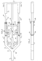
- the frame of the embodiment comprises a first frame portion 10 and a second frame portion 11 which can be adjusted from an inwardly closed shorter position shown in figure 1 to an extended position shown in Figure 2.
- the first frame portion 10 comprises a first beam 12 and a second beam 13 which are parallel and parallel to a direction of longitudinal movement of the trailer as indicated at 14.
- the beams 12 and 13 are indicated by a first transverse beam 15 and a second rear transverse beam 17.
- a pair of inwardly inclined beam portions 18 and 19 which converge to central apex at which is provided a hitch pole 20 extending forwardly from the frame for attachment to a towing vehicle.
- the rear or second frame portion comprises a first beam 21 and a second beam 22.
- first and second beams 21, 22 is formed of a first tubular portion 23 of the same dimensions as a tubular portion forming the beam 12,13 and a second tubular portion of reduced dimensions for sliding inside of the tubular portion defining the beam 12,13.
- the end 24 of the portion 23 lies substantially immediately adjacent the end 25 of the beam 12.
- a pair of rollers 27, 28 which roll on the outside surface of the smaller portion of the beams 21, 22.
- the smaller portions of the beam 21 and 22 are guided by the pair of roller as best shown in Figure 3 for sliding movement longitudinally of the beams 12, 13.
- the longitudinal sliding movement of the rear portion 11 or of the front portion 12 is then effected by a cylinder schematically indicated at 29 which is connected between a coupling 30 at the rear end of the hitch pole 20 and a coupling 31 on the rear frame portion 11.
- the rear frame 11 further includes a third beam 32 parallel to and coplanar with the beams 21 and 22.
- the three beams are indicated by a transverse rear beam 33 defining a rear part of the frame with the rear beam extending outwardly beyond the beams 21 and 22 to form projecting portions 33A and 33B.
- the third beam 32 rides on a roller 35 carried on a rear upper part of the transverse beam 17. Forwardly the roller 35, the beam 32 splits into two transverse members 36 and 37 which diverge outwardly in a Y-shape toward the beams 12 and 13. Adjacent the forward end of each of the transverse members is provided a horizontal shaft 38 each of which carries a roller 39 running within a channel guide track 40 mounted on an inwardly facing surface of the respective beam 12, 13.
- the coupling 31 is located at the apex between the legs of the Y-shape.
- Each frame portion comprises a horizontal beam 46 which is supported on the respective beam 12, 13 by a pair of inclined support struts 47, 47A.
- Each of the struts 47, 47A is attached to a plate 48 at its inner end bolted to the outside surface of the beam 12.
- the beam 46 is supported at a height raise from the horizontal plane of the main frame.
- the beam 46 is however rigidly attached to the main frame and remains in fixed position relative to thereto.
- the frame thus constructed by a pair of wheel assemblies generally indicated at 50. Again the right hand wheel assembly is shown in Figure 1 and the left hand wheel assembly is omitted for convenience of illustration. It will be appreciated that the frame portion 45 and the wheel 50 of the right is symmetrical relative to the same elements on the left hand side.
- the wheel assembly 50 comprises a ground wheel 51, a wheel mounting assembly 52, a pivot arm 53 and a leaf spring 54.
- the pivot arm 53 is pivotally connected by a bracket 55 attached to the beam 1 by a plate 56 intermediate the plate 48.
- the arm 53 can thus pivot upwardly and downwardly in a suspension movement of the wheel against the bias of the spring 54 attached to the beam 46 by couplings 54A.
- the arm 53 projects beyond its connection to the base of the leaf spring 54 and thus provides a support for the wheel mounting 52.
- the wheel mounting 52 comprised a first member 60 in the form of a substantially vertical plate welded to an outer end 61 of the arm 53 and standing upwardly therefrom so the arm is attached to the bottom of the plate 60.
- the plate carries a spindle 62 projecting forwardly from the plate at a position directly above the arm and extending horizontally from the plate when the plate stands vertical. The angle of the plate varies during suspension movement.
- the mounting assembly 52 further includes a hub 63 forming a second member of the mounting assembly which is movable relative to the first member.
- the hub 63 includes a central ring 64 mounted on the spindle 62 for rotation about a rotation axis 65 defined by the spindle 62.
- the hub 63 carries a spindle 66 for the wheel 51 defining a wheel axis 67 about which the wheel rotates on the spindle 65.
- the spindle 65 is located either position spaced from the spindle 62 with the axis 65 and 67 parallel.
- the hub 63 includes and outer ring 68 surrounding the axis 65 with the outer ring including an inwardly facing gear 69.
- a pinion 70 is mounted on a shaft 71 extending through the plate 60 and carried thereby on suitable bearings.
- the shaft 71 is parallel to the axis 65 and drives the pinion in rotation about the axis of the shaft so as to drive the gear 69 in rotation around the axis 65.
- the shaft 71 is driven by a hydraulic motor 72 carried on a support plate 73 attached to the arm 53 of a position thereon spaced from the plate 60 and inwardly of the spring 54.
- the plate 73 is based by a triangular base 74.
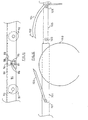
- Rotation of the shaft 71 effected by the hydraulic motor 72 thus causes the pinion to drive the hub 63 around the axis 65 from the first raised position of the spindle 66 as shown in Figure 7 to the second lowered position of the spindle 66 as shown in Figures 5, 6 and 8.
- the spindle 66 In the raised position of the spindle 66 as shown in Figure 7, the spindle is moved to a top center position directly above the axis 65. In this position the wheel 51 is raised relative to the frame.
- the wheel 51 has a diameter arranged that such that in raised position shown in Figure 7 the frame is substantially at or adjacent ground height so that a load can be moved directly on to the trailer.
- the spindle 66 tends to center itself over the axis 65 due to the loading of the wheel on the hub 63 which tend to pull the hub upwardly in rotation relative to the plate 60.
- the motor 72 is actuated to drive the shaft 71 causing the pinion the drive the gear in a direction rotating the hub 63 from the 12 o'clock position illustrated in dotted line at 66A in Figure 6 to the 6.30 position shown in full line in Figure 6.
- the spindle 66 in the lowered position goes just beyond the bottom centered position that is slightly over-center until the hub 63 engages against a stop 75 carried on the plate 60.
- the hub 63 includes a lobe 76 projecting outwardly to one side of the ring 68 with the lobe defining a side wall 77 which engages against the stop 75.
- the stop forms a surface which is oriented to engage the surface 77 when the lobe moves to the required position holding the spindle 66 at the 6.30 position.
- the stop 75 includes an end plate portion 78 projecting beyond a front face 79 of the hub 63.
- the end plate portion 78 defines a lip which is in sliding contact with the front face 79 so as to hold that front face against movement away from the plate 60.
- the lip 78 thus takes loading from the spindle 62 and insures that excessive loading on the spindle 65 tending to twist the bottom of the hub away from the plates 60 is resisted by the inter-engagement between the lip 78 and the surface 79.
- the trailer therefore the present invention allows the frame of the trailer to be lowered to the ground for loading and the frame of the trailer to be lifted for transport.
- the lifting action is effected using hydraulic action without operator involvement in latching or unlatch elements.
- the trailer can be adjusted in length to accommodate different loads with the whole of the frame including the adjustable rear portion being movable in the vertical direction for the loading action.
- FIG. 9, 10 and 11 there is shown a fender for the trailer as shown and described above.
- the normal position of the fender just above the wheel during transport movement of the trailer is necessary to prevent release of water, mud and other materials from the road and therefore in the normal position of the trailer, the fender is closely adjacent the wheel. When the wheel is raised, however, the fender must accommodate this movement.
- FIGS 9, 10 and 11 One technique for accommodating movement is shown in Figures 9, 10 and 11 wherein there is provided a fender 80 forming two parts 81 and 82.
- the fender is mounted on the frame member 46 and projects outwardly therefrom over the wheel 83.
- Each fender piece 81, 82 is mounted on a respective one of a pair of pins 84 and 85 mounted on a projecting outwardly from the frame member 46.
- each fender piece 81, 82 includes a sleeve 86 surrounding the respective pin which is attached to the fender portion by any suitable technique such as welding.
- the sleeve 86 is arranged at the forward end of the portion 81 and at the rearward end of the portion 82. The sleeve can thus rotate around the pin allowing the fender portion to raise and lower as required.
- a spring 87 biases the fender portion into the lowered position.
- the fender portion 81 is the forward portion and extends from the sleeve 86 on the pin 84 to a rearward edge 88 which is chamfered as indicated in Figure 10.
- the rearward portion 82 has a forward chamfered end 89 which matches the chamfered end 88 so that the end 88 rests over the end 89.
- the sleeve 86 of the portion 82 is arranged at the rearward end and behind the sleeve is provided a downwardly depending mud flap 90.
- Each portion carries a roller 91, 92 which contacts the peripheral surface of the wheel as the wheel is raised upwardly so as to push the portions upwardly as the wheel is raised.
- the roller is carried on a pin 93 projecting inwardly from an outer flange 94 of the fender.
- the fender portions can be locked in place by a pair of locking members 94 and 95 mounted on one edge of the fender, which can be the inside edge, the outside edge or both edges, at the chamfered edges 88 and 89.
- the locking member 94 comprises an upper cap portion carrying a depending pin 96.
- the lower locking member 95 comprises a sleeve having an internal bore 97 into which the pin 96 seats.
- FIG. 12 An alternative arrangement is shown in Figure 12 where the side frame member 101 carries the fender generally indicated at 102 formed by two fender portions 103 and 104 substantially as previously described.
- the frame member 101 includes an extension portion 105 which slides inside the tubular frame member 101 so as to allow the frame member to extend.
- the front portion 103 is mounted on a sleeve and pin arrangement 107 as previously described.
- the rear portion 104 is mounted on a similar sleeve and pin arrangement as indicated at 108.
- the sleeve and pin 107 is mounted on the frame members 101.
- the sleeve and pin 108 is mounted on the frame member 105 and is therefore movable rearwardly as the frame is extended by pulling out the extension portion 105.
- the sleeve and pin arrangement 108 therefore moves from an initial position as shown at 109 in the normal operating position of the fender to an extended position as shown at 108.
- the rear portion instead of the rear portion pivoting upwardly on the spring, the rear portion remains at a fixed height but is instead moved horizontally away from the position of the wheel 110 allowing the wheel to move upwardly and providing a pushing action only on the forward portion 103.
- the fender can also be designed for use with a dual axle arrangement in which the length of one or both portions is increased to accommodate the length of the wheels on the dual axle.
Landscapes
- Engineering & Computer Science (AREA)
- Mechanical Engineering (AREA)
- Transportation (AREA)
- Chemical & Material Sciences (AREA)
- Combustion & Propulsion (AREA)
- Health & Medical Sciences (AREA)
- Public Health (AREA)
- Body Structure For Vehicles (AREA)
- Agricultural Machines (AREA)
- Saccharide Compounds (AREA)
Claims (10)
- Fahrzeug, umfassend:wobei jede Montagebaugruppe umfasst:einen Fahrzeugrahmen (11) mit mindestens zwei zu einer Bewegungsrichtung des Fahrzeuges parallelen Längsträgern (46);mindestens zwei Bodenrädern (51) zum Tragen des Rahmens für die Bewegung über den Boden; undwenigstens zwei Montagebaugruppen (52), die jeweils einem Bodenrad zugeordnet sind, zum Befestigen des Bodenrades an dem Rahmen;DADURCH GEKENNZEICHNET, DASSein erstes Bauteil (60), das beweglich mit dem Rahmen verbunden ist; undein zweites Drehbauteil (63), an dem das Rad zur Drehung um eine Radachse (67) befestigt ist;
wobei das zweite Drehbauteil drehbar an dem ersten Bauteil für eine zu ihm relative Drehbewegung um eine Drehachse (65) befestigt ist, welche parallel und beabstandet zur Radachse liegt, um so die Radachse von einer ersten angehobenen Position (66A), in der der Rahmen in eine Position am oder benachbart zum Boden abgesenkt ist, in eine zweite Betriebsposition (66), die niedriger als die erste Position ist und in welcher der Rahmen zum Transport angehoben ist, zu bewegen; undMittel (69, 70) zum Antrieb der Drehbewegung zwischen der angehobenen Position und der zweiten Betriebsposition,
das Mittel zum Antrieb ein auf dem zweiten Bauteil gelagertes Zahnrad (69) und ein auf dem ersten Bauteil gelagertes Ritzel (70) umfasst, um das Zahnrad treibend zu bewegen und somit das zweite Bauteil bezüglich des ersten Bauteiles zu drehen. - Fahrzeug nach Anspruch 1, wobei das Mittel zum Antreiben derart angeordnet ist, dass die Radachse (67) in der ersten angehobenen Position im Wesentlichen direkt über der Drehachse (65) liegt und in der zweiten Betriebsposition die Radachse (67) über einen Winkel von im Wesentlichen gleich 180 Grad bewegt wird, so dass die Radachse im Wesentlichen direkt unter der Drehachse (65) liegt.
- Fahrzeug nach Anspruch 1 oder 2, wobei das Ritzel (70) durch einen Motor (72) angetrieben ist, das erste Bauteil (60) eine im Wesentlichen vertikale Platte enthält und wobei das zweite Bauteil (63) für die Drehbewegung an der Platte außen von der Platte befestigt ist und wobei der Motor von der Platte aus innen liegend angebracht ist und die Motorwelle durch die Platte hindurch geht, um das Zahnrad (69) des zweiten Bauteiles (63) in Eingriff zu bringen.
- Fahrzeug nach Anspruch 3, wobei das zweite Bauteil (63) eine Nabe umfasst, die eine Hauptnabenplatte aufweist, die parallel zur Platte des ersten Bauteiles (60) ist, mit einem ringförmigen Kranz, der an der Hauptnabenplatte angebracht ist und von ihr zur Platte des ersten Bauteiles hin vorspringt, wobei das Zahnrad (69) auf einer zur Achse hin gerichteten Fläche des ringförmigen Kranzes festgelegt ist.
- Fahrzeug nach Anspruch 4, wobei Zwischeneingriffsmittel (78, 79) auf der Hauptnabenplatte und der Platte vorgesehen sind, um das Wegdrehen der Hauptnabenplatte von der Platte zu verhindern, wenn sie sich in der zweiten Betriebsposition befindet.
- Fahrzeug nach Anspruch 1, 2, 3, 4 oder 5, wobei sich die Radachse in der zweiten Betriebsposition in einer Position gerade über eine untere Mittenposition hinaus bewegt und wobei an dem ersten Bauteil ein Anschlag (75) vorgesehen ist zur Festlegung der Radachse des zweiten Bauteiles in der zweiten Betriebsposition gerade über den unteren Todpunkt hinaus, so dass senkrechte Lasten auf das Rad bestrebt sind, das zweite Bauteil gegen den Anschlag zu drücken.
- Fahrzeug nach einem der vorherigen Ansprüche, wobei der Rahmen umfasst;
einen vorderen Rahmenabschnitt (10) und einen hinteren Rahmenabschnitt (11);
wobei die Bodenräder (50) an dem vorderen Rahmenabschnitt angebracht sind, um den vorderen Rahmenabschnitt zu tragen, so dass der hintere Rahmenabschnitt bezüglich des Bodens alleine vom vorderen Rahmenabschnitt getragen wird;
wobei der hintere Rahmenabschnitt Stützelemente (21, 22) enthält, die am vorderen Rahmenabschnitt befestigt sind, um so für eine bezüglich des vorderen Rahmenabschnittes gleitende Bewegung nach vorne und nach hinten der Stützelemente und des hinteren Rahmenabschnittes zwischen einer nach vorne hin zurückgezogenen Position und einer nach hinten hin ausgestreckten Position zu sorgen;
wobei der hintere Rahmenabschnitt Rahmenstützelemente (23) für eine hintere Last enthält, die über ein hinteres Ende des vorderen Rahmenabschnittes hinaus angeordnet sind und dafür geeignet sind, einen hinteren Teil einer Last auf dem Fahrzeug abzustützen; und
wobei der hintere Rahmenabschnitt zusätzlich zu den Stützelementen (21, 22) ein Rahmenstützelement (32) für eine vordere Last enthält, das sich vom hinteren Rahmenabschnitt (23) aus nach vorne erstreckt, um so in einer zurückgezogenen Position an einem vorderen Teil des vorderen Rahmenabschnittes festgelegt zu werden. - Fahrzeug nach einem der vorherigen Ansprüchen, weiter umfassend eine am Fahrzeugrahmen angebrachte Schutzhaube (80), um das Rad während des Transportes abzudecken, wobei die Schutzhaube wenigstens einen Abschnitt (81, 82) enthält, der für die Drehbewegung um eine im Allgemeinen horizontale Achse (86) befestigt ist, um sich mit dem Rad nach oben zu bewegen, wenn sie vom Rad berührt wird.
- Fahrzeug nach Anspruch 8, wobei die Schutzhaube von zwei Abschnitten (81, 82) gebildet wird, die an einer Linie (88) über dem Rad abgeteilt sind, wobei jeder drehbar um jeweils eine Drehachse (86) befestigt ist und die Abschnitte eine Verriegelungsvorrichtung (95) enthalten zur Verriegelung der Abschnitte miteinander in der Transportposition.
- Fahrzeug nach Anspruch 8 oder 9, wobei der Rahmen einen Verlängerungsabschnitt (105) enthält, der längs des Rahmens bewegbar ist, und wobei die Schutzhaube einen an dem Verlängerungsabschnitt des Rahmens angebrachten Abschnitt (104) enthält, um damit so in eine vom Rad beabstandete Position bewegbar zu sein, um die Bewegung des Rades nach oben zu erlauben.
Applications Claiming Priority (5)
| Application Number | Priority Date | Filing Date | Title |
|---|---|---|---|
| US906905 | 1997-08-06 | ||
| US08/906,905 US5984340A (en) | 1997-08-06 | 1997-08-06 | Trailer |
| US9648598A | 1998-06-10 | 1998-06-10 | |
| US96485 | 1998-06-10 | ||
| PCT/CA1998/000752 WO1999007595A1 (en) | 1997-08-06 | 1998-08-06 | Trailer |
Publications (2)
| Publication Number | Publication Date |
|---|---|
| EP0999973A1 EP0999973A1 (de) | 2000-05-17 |
| EP0999973B1 true EP0999973B1 (de) | 2003-05-21 |
Family
ID=26791749
Family Applications (1)
| Application Number | Title | Priority Date | Filing Date |
|---|---|---|---|
| EP98938562A Expired - Lifetime EP0999973B1 (de) | 1997-08-06 | 1998-08-06 | Anhänger |
Country Status (9)
| Country | Link |
|---|---|
| EP (1) | EP0999973B1 (de) |
| JP (1) | JP2001513468A (de) |
| CN (1) | CN1128081C (de) |
| AT (1) | ATE240866T1 (de) |
| AU (1) | AU731962B2 (de) |
| CA (2) | CA2299228C (de) |
| DE (1) | DE69814864T2 (de) |
| ES (1) | ES2200357T3 (de) |
| WO (1) | WO1999007595A1 (de) |
Cited By (4)
| Publication number | Priority date | Publication date | Assignee | Title |
|---|---|---|---|---|
| US6986519B2 (en) | 1997-01-31 | 2006-01-17 | Aloha, Llc | Low profile chassis and suspension |
| US7108271B2 (en) | 1997-01-31 | 2006-09-19 | Earl Dallas Smith | Axleless vehicle suspension system |
| US7425005B2 (en) | 2003-10-24 | 2008-09-16 | Aloha, Llc | Suspensions for low floor vehicles |
| US7559400B2 (en) | 1997-01-31 | 2009-07-14 | Aloha, Llc | Low profile chassis and suspension |
Families Citing this family (15)
| Publication number | Priority date | Publication date | Assignee | Title |
|---|---|---|---|---|
| US6451813B1 (en) | 2001-01-26 | 2002-09-17 | R. T. Alamo Ventures I, Llc | Treatment of gastroparesis in certain patient groups |
| GB2398045B (en) * | 2003-02-04 | 2006-02-15 | James Leonard Beckett | Improved fork lift truck |
| DE202014101630U1 (de) | 2014-04-07 | 2015-07-08 | Ulrich Humbaur | Absenkbarer Fahrzeuganhänger |
| FR3037310B1 (fr) * | 2015-06-09 | 2018-10-19 | Renault S.A.S | Remorque comportant un moyen d'immobilisation, vehicule commandant l'immobilisation et l'attelage reversibles de la remorque, ensemble forme par l'attelage d'une telle remorque et d'un tel vehicule |
| CN105034922B (zh) * | 2015-08-24 | 2018-01-12 | 浙江双友物流器械股份有限公司 | 一种拖车的运送装置 |
| US10005504B2 (en) | 2015-09-22 | 2018-06-26 | Khoa Van Tran | Towing systems |
| USD823732S1 (en) | 2016-09-21 | 2018-07-24 | Khoa Van Tran | Motorcycle transport trailer |
| US10543875B2 (en) | 2016-12-20 | 2020-01-28 | Équipement Max-Atlas International Inc. | Extendable trailer for freight containers |
| CN110949083B (zh) * | 2019-11-01 | 2021-07-09 | 江苏科技大学 | 气囊驱动式拖车的平动升降控制系统及控制方法 |
| CN111038592B (zh) * | 2020-01-08 | 2021-07-27 | 吉林工程技术师范学院 | 一种可升降式越野车车架装置 |
| CN111845237A (zh) * | 2020-07-15 | 2020-10-30 | 广东博智林机器人有限公司 | 一种驱动装置 |
| CN111890860A (zh) * | 2020-08-05 | 2020-11-06 | 广东博智林机器人有限公司 | 一种减震装置、移动底盘和移动式建筑设备 |
| US12240549B1 (en) | 2021-03-31 | 2025-03-04 | Khoa Van Tran | Towable trailer systems |
| USD1009708S1 (en) | 2021-04-05 | 2024-01-02 | Khoa Van Tran | Towing system |
| US12515576B1 (en) | 2022-06-17 | 2026-01-06 | Khoa Van Tran | Towable trailer system |
Family Cites Families (2)
| Publication number | Priority date | Publication date | Assignee | Title |
|---|---|---|---|---|
| US3746195A (en) * | 1971-09-20 | 1973-07-17 | Peters C | Lowering bed trailer |
| US5161814A (en) * | 1989-04-28 | 1992-11-10 | Walker Douglas W | Trailerable structure with retractable suspension |
-
1998
- 1998-08-06 DE DE69814864T patent/DE69814864T2/de not_active Expired - Lifetime
- 1998-08-06 AU AU87243/98A patent/AU731962B2/en not_active Ceased
- 1998-08-06 CA CA002299228A patent/CA2299228C/en not_active Expired - Fee Related
- 1998-08-06 AT AT98938562T patent/ATE240866T1/de not_active IP Right Cessation
- 1998-08-06 JP JP2000507144A patent/JP2001513468A/ja active Pending
- 1998-08-06 WO PCT/CA1998/000752 patent/WO1999007595A1/en not_active Ceased
- 1998-08-06 EP EP98938562A patent/EP0999973B1/de not_active Expired - Lifetime
- 1998-08-06 ES ES98938562T patent/ES2200357T3/es not_active Expired - Lifetime
- 1998-08-06 CN CN98808001.XA patent/CN1128081C/zh not_active Expired - Fee Related
- 1998-08-06 CA CA002380282A patent/CA2380282C/en not_active Expired - Fee Related
Cited By (5)
| Publication number | Priority date | Publication date | Assignee | Title |
|---|---|---|---|---|
| US6986519B2 (en) | 1997-01-31 | 2006-01-17 | Aloha, Llc | Low profile chassis and suspension |
| US7108271B2 (en) | 1997-01-31 | 2006-09-19 | Earl Dallas Smith | Axleless vehicle suspension system |
| US7559400B2 (en) | 1997-01-31 | 2009-07-14 | Aloha, Llc | Low profile chassis and suspension |
| US7425005B2 (en) | 2003-10-24 | 2008-09-16 | Aloha, Llc | Suspensions for low floor vehicles |
| US7703781B2 (en) | 2003-10-24 | 2010-04-27 | Aloha, Llc | Suspensions for low floor vehicle |
Also Published As
| Publication number | Publication date |
|---|---|
| CN1266402A (zh) | 2000-09-13 |
| CA2380282C (en) | 2002-12-10 |
| JP2001513468A (ja) | 2001-09-04 |
| DE69814864T2 (de) | 2004-05-06 |
| EP0999973A1 (de) | 2000-05-17 |
| AU731962B2 (en) | 2001-04-05 |
| ATE240866T1 (de) | 2003-06-15 |
| WO1999007595A1 (en) | 1999-02-18 |
| AU8724398A (en) | 1999-03-01 |
| CA2299228A1 (en) | 1999-02-18 |
| CA2299228C (en) | 2002-10-15 |
| ES2200357T3 (es) | 2004-03-01 |
| CN1128081C (zh) | 2003-11-19 |
| DE69814864D1 (de) | 2003-06-26 |
Similar Documents
| Publication | Publication Date | Title |
|---|---|---|
| EP0999973B1 (de) | Anhänger | |
| US6474672B1 (en) | Adjustable vehicle with moving section for load transfer | |
| CA2262457C (en) | Advanced rollback wheel-lift | |
| US8132997B2 (en) | Lift apparatus mountable on a vehicle | |
| US2628733A (en) | Towing dolly | |
| US4210217A (en) | Self-propelled steering device for trailers | |
| US6461096B1 (en) | Tilt bed for loading and transporting a load | |
| US6183187B1 (en) | Integrated lift and tow hitch | |
| US5308213A (en) | Ground level loading universal trailer | |
| US4943118A (en) | End dumping trailer | |
| US6050578A (en) | Log trailer load booster | |
| EP0440571B1 (de) | Einheitliche Handhabungsvorrichtung für die Hinterachse eines Strassenfahrzeuges oder eines Anhängers | |
| US6113338A (en) | Rear loading trailer and method of use | |
| US3717363A (en) | Convertible dolly-tandem axle | |
| EP1456043B1 (de) | Stützbeinanordnung für fahrzeuganhänger | |
| US5215425A (en) | Tractor towing apparatus | |
| US6749205B2 (en) | Vehicle with adjustable height wheel and fender therefor | |
| US5984340A (en) | Trailer | |
| US6712380B1 (en) | Trailer | |
| CN210971332U (zh) | 一种鹅颈可分离的低平板半挂车 | |
| CA2380193C (en) | Vehicle with adjustable height wheel and fender therefor | |
| US20100044997A1 (en) | Fifth wheel hitch cart assembly | |
| US3963257A (en) | Roll handling | |
| US4838754A (en) | Method and apparatus for connecting a rear trailer in a tandem tractor-trailer assembly | |
| MXPA00001280A (es) | Vehiculo |
Legal Events
| Date | Code | Title | Description |
|---|---|---|---|
| PUAI | Public reference made under article 153(3) epc to a published international application that has entered the european phase |
Free format text: ORIGINAL CODE: 0009012 |
|
| 17P | Request for examination filed |
Effective date: 20000221 |
|
| AK | Designated contracting states |
Kind code of ref document: A1 Designated state(s): AT BE CH CY DE DK ES FI FR GB GR IE IT LI LU MC NL PT SE |
|
| 17Q | First examination report despatched |
Effective date: 20020226 |
|
| GRAH | Despatch of communication of intention to grant a patent |
Free format text: ORIGINAL CODE: EPIDOS IGRA |
|
| GRAH | Despatch of communication of intention to grant a patent |
Free format text: ORIGINAL CODE: EPIDOS IGRA |
|
| GRAA | (expected) grant |
Free format text: ORIGINAL CODE: 0009210 |
|
| AK | Designated contracting states |
Designated state(s): AT BE CH CY DE DK ES FI FR GB GR IE IT LI LU MC NL PT SE |
|
| PG25 | Lapsed in a contracting state [announced via postgrant information from national office to epo] |
Ref country code: NL Free format text: LAPSE BECAUSE OF FAILURE TO SUBMIT A TRANSLATION OF THE DESCRIPTION OR TO PAY THE FEE WITHIN THE PRESCRIBED TIME-LIMIT Effective date: 20030521 Ref country code: LI Free format text: LAPSE BECAUSE OF FAILURE TO SUBMIT A TRANSLATION OF THE DESCRIPTION OR TO PAY THE FEE WITHIN THE PRESCRIBED TIME-LIMIT Effective date: 20030521 Ref country code: FI Free format text: LAPSE BECAUSE OF FAILURE TO SUBMIT A TRANSLATION OF THE DESCRIPTION OR TO PAY THE FEE WITHIN THE PRESCRIBED TIME-LIMIT Effective date: 20030521 Ref country code: CH Free format text: LAPSE BECAUSE OF FAILURE TO SUBMIT A TRANSLATION OF THE DESCRIPTION OR TO PAY THE FEE WITHIN THE PRESCRIBED TIME-LIMIT Effective date: 20030521 Ref country code: BE Free format text: LAPSE BECAUSE OF FAILURE TO SUBMIT A TRANSLATION OF THE DESCRIPTION OR TO PAY THE FEE WITHIN THE PRESCRIBED TIME-LIMIT Effective date: 20030521 Ref country code: AT Free format text: LAPSE BECAUSE OF FAILURE TO SUBMIT A TRANSLATION OF THE DESCRIPTION OR TO PAY THE FEE WITHIN THE PRESCRIBED TIME-LIMIT Effective date: 20030521 |
|
| REG | Reference to a national code |
Ref country code: GB Ref legal event code: FG4D |
|
| REG | Reference to a national code |
Ref country code: CH Ref legal event code: EP |
|
| REG | Reference to a national code |
Ref country code: IE Ref legal event code: FG4D |
|
| REF | Corresponds to: |
Ref document number: 69814864 Country of ref document: DE Date of ref document: 20030626 Kind code of ref document: P |
|
| PG25 | Lapsed in a contracting state [announced via postgrant information from national office to epo] |
Ref country code: LU Free format text: LAPSE BECAUSE OF NON-PAYMENT OF DUE FEES Effective date: 20030806 Ref country code: IE Free format text: LAPSE BECAUSE OF NON-PAYMENT OF DUE FEES Effective date: 20030806 Ref country code: CY Free format text: LAPSE BECAUSE OF FAILURE TO SUBMIT A TRANSLATION OF THE DESCRIPTION OR TO PAY THE FEE WITHIN THE PRESCRIBED TIME-LIMIT Effective date: 20030806 |
|
| PG25 | Lapsed in a contracting state [announced via postgrant information from national office to epo] |
Ref country code: SE Free format text: LAPSE BECAUSE OF FAILURE TO SUBMIT A TRANSLATION OF THE DESCRIPTION OR TO PAY THE FEE WITHIN THE PRESCRIBED TIME-LIMIT Effective date: 20030821 Ref country code: PT Free format text: LAPSE BECAUSE OF FAILURE TO SUBMIT A TRANSLATION OF THE DESCRIPTION OR TO PAY THE FEE WITHIN THE PRESCRIBED TIME-LIMIT Effective date: 20030821 Ref country code: GR Free format text: LAPSE BECAUSE OF FAILURE TO SUBMIT A TRANSLATION OF THE DESCRIPTION OR TO PAY THE FEE WITHIN THE PRESCRIBED TIME-LIMIT Effective date: 20030821 Ref country code: DK Free format text: LAPSE BECAUSE OF FAILURE TO SUBMIT A TRANSLATION OF THE DESCRIPTION OR TO PAY THE FEE WITHIN THE PRESCRIBED TIME-LIMIT Effective date: 20030821 |
|
| PG25 | Lapsed in a contracting state [announced via postgrant information from national office to epo] |
Ref country code: MC Free format text: LAPSE BECAUSE OF NON-PAYMENT OF DUE FEES Effective date: 20030831 |
|
| NLV1 | Nl: lapsed or annulled due to failure to fulfill the requirements of art. 29p and 29m of the patents act | ||
| REG | Reference to a national code |
Ref country code: CH Ref legal event code: PL |
|
| REG | Reference to a national code |
Ref country code: ES Ref legal event code: FG2A Ref document number: 2200357 Country of ref document: ES Kind code of ref document: T3 |
|
| PLBE | No opposition filed within time limit |
Free format text: ORIGINAL CODE: 0009261 |
|
| STAA | Information on the status of an ep patent application or granted ep patent |
Free format text: STATUS: NO OPPOSITION FILED WITHIN TIME LIMIT |
|
| ET | Fr: translation filed | ||
| 26N | No opposition filed |
Effective date: 20040224 |
|
| REG | Reference to a national code |
Ref country code: IE Ref legal event code: MM4A |
|
| PGFP | Annual fee paid to national office [announced via postgrant information from national office to epo] |
Ref country code: FR Payment date: 20120906 Year of fee payment: 15 Ref country code: ES Payment date: 20120816 Year of fee payment: 15 |
|
| REG | Reference to a national code |
Ref country code: FR Ref legal event code: ST Effective date: 20140430 |
|
| PG25 | Lapsed in a contracting state [announced via postgrant information from national office to epo] |
Ref country code: FR Free format text: LAPSE BECAUSE OF NON-PAYMENT OF DUE FEES Effective date: 20130902 |
|
| REG | Reference to a national code |
Ref country code: ES Ref legal event code: FD2A Effective date: 20140905 |
|
| PG25 | Lapsed in a contracting state [announced via postgrant information from national office to epo] |
Ref country code: ES Free format text: LAPSE BECAUSE OF NON-PAYMENT OF DUE FEES Effective date: 20130807 |
|
| PGFP | Annual fee paid to national office [announced via postgrant information from national office to epo] |
Ref country code: DE Payment date: 20150821 Year of fee payment: 18 Ref country code: GB Payment date: 20150819 Year of fee payment: 18 |
|
| PGFP | Annual fee paid to national office [announced via postgrant information from national office to epo] |
Ref country code: IT Payment date: 20150824 Year of fee payment: 18 |
|
| REG | Reference to a national code |
Ref country code: DE Ref legal event code: R082 Ref document number: 69814864 Country of ref document: DE Representative=s name: JOSTARNDT PATENTANWALTS-AG, DE |
|
| REG | Reference to a national code |
Ref country code: DE Ref legal event code: R119 Ref document number: 69814864 Country of ref document: DE |
|
| GBPC | Gb: european patent ceased through non-payment of renewal fee |
Effective date: 20160806 |
|
| PG25 | Lapsed in a contracting state [announced via postgrant information from national office to epo] |
Ref country code: DE Free format text: LAPSE BECAUSE OF NON-PAYMENT OF DUE FEES Effective date: 20170301 Ref country code: GB Free format text: LAPSE BECAUSE OF NON-PAYMENT OF DUE FEES Effective date: 20160806 |
|
| PG25 | Lapsed in a contracting state [announced via postgrant information from national office to epo] |
Ref country code: IT Free format text: LAPSE BECAUSE OF NON-PAYMENT OF DUE FEES Effective date: 20160806 |