EP0999534B1 - Übungssimulator - Google Patents
Übungssimulator Download PDFInfo
- Publication number
- EP0999534B1 EP0999534B1 EP99118219A EP99118219A EP0999534B1 EP 0999534 B1 EP0999534 B1 EP 0999534B1 EP 99118219 A EP99118219 A EP 99118219A EP 99118219 A EP99118219 A EP 99118219A EP 0999534 B1 EP0999534 B1 EP 0999534B1
- Authority
- EP
- European Patent Office
- Prior art keywords
- simulator according
- module
- image
- projection
- cab
- Prior art date
- Legal status (The legal status is an assumption and is not a legal conclusion. Google has not performed a legal analysis and makes no representation as to the accuracy of the status listed.)
- Expired - Lifetime
Links
Images


Classifications
-
- G—PHYSICS
- G09—EDUCATION; CRYPTOGRAPHY; DISPLAY; ADVERTISING; SEALS
- G09B—EDUCATIONAL OR DEMONSTRATION APPLIANCES; APPLIANCES FOR TEACHING, OR COMMUNICATING WITH, THE BLIND, DEAF OR MUTE; MODELS; PLANETARIA; GLOBES; MAPS; DIAGRAMS
- G09B9/00—Simulators for teaching or training purposes
- G09B9/02—Simulators for teaching or training purposes for teaching control of vehicles or other craft
- G09B9/04—Simulators for teaching or training purposes for teaching control of vehicles or other craft for teaching control of land vehicles
- G09B9/05—Simulators for teaching or training purposes for teaching control of vehicles or other craft for teaching control of land vehicles the view from a vehicle being simulated
Definitions
- the invention relates to an exercise simulator for training of persons in the leadership of vehicles, especially commercial vehicles, the type specified in the preamble of claim 1.
- the projection screen is composed of flat individual surfaces that connect along a complete the driver's cab from the front polygon seamlessly.
- the individual surfaces are held by means of a frame consisting of a vertical holding mast and a horizontal guide rail mounted on the ground.
- the image projectors, each illuminating a single area of the projection screen, are divided into two groups.
- the image projectors for the middle individual areas are arranged in the apparent direction of travel behind the projection screen. The outgoing from these projectors light bundle hit by arranged in the individual areas passages on the passages associated deflection mirror and fall onto the screen in front of the driver's cab.
- the image projectors for the further outlying individual surfaces are arranged above the driver's cab and their light bundles fall over deflecting mirrors mounted on the roof of the driver's cabin onto the vehicle Projection screen.
- This reflected light projection has the disadvantage that when using a usually required, original driver's cab and the adaptation of the simulated environment to the driver's field of view because of the large dimensions of the cab and the extreme dimensions of the field of view, a shadow-proof projection can only be achieved if the screen far away from the driver's cab and the projectors are placed high above the driver's cab.
- This requires large dimensions of the driving simulator which on the one hand requires high buildings to accommodate it and on the other hand, the placement of the simulator on a motion system, eg for acceleration simulation, considerably more difficult.
- three large-screen projectors are provided for the representation of the simulated environment, which represent by means of transmitted light projection portions of the visible panorama on one of three trapezoidal in front of the driver's cab, transparent projection screens.
- the large-screen projectors are arranged on the rear side of the projection screens facing away from the driver's cab, and each large-screen projector projects a sector of a panorama extending over 180 ° onto the rear side of the projection screen via a deflection mirror.
- Transmitted light or rear projection has the advantage that the light paths for image generation and image perception are strictly separated and thereby the projection screen can be brought closer to the driver's cab, resulting in smaller dimensions of the simulator and brighter images.
- the disadvantage is that the projection screens are relatively unstable and are also not suitable for mounting on a movement system.
- the invention has for its object to provide an exercise simulator of the type mentioned with low height and small width, in which without significant design changes to the vehicle adapted to different fields of vision on the projection screen can be designed and the image display system has a high mechanical stability, so that the simulator, eg for acceleration simulation, can also be installed on a motion system.
- the exercise simulator according to the invention has the advantage that the projection screen has a high stability by the one-piece, by clamping in the brackets cylindrically curved transparent plastic transparency, which even meets the requirements of installation on a movement system.
- the transmission lens By maintaining the transmitted light projection the strict separation of the light paths for the image production and perception is given, so that on the one hand the transmission lens can be arranged relatively close to the driver's cabin and on the other hand, the image projectors can be placed near the ground and thus small overall dimensions for the exercise simulator can be achieved.
- the field of view can be adapted to the extent required by the field of vision required for the respective training vehicle.
- the translucent lens poses no special requirement for production and transport, since it is flat and only curved during its assembly. The assembly is simple and not very time-consuming, as it only in the on a circular arc arranged brackets must be used, which clamp the transmitted-light disk at its upper and lower edges.
- each holder is formed on a mounting module, and the modules are circular segment-shaped so that they can be connected to each other to form a partially or fully closed cylinder and firmly connected to each other.
- This modular design offers the possibility to adapt the projection screen in the horizontal direction to the field of view required for the special simulator by simply adding or removing modules.
- the size of the translucent lens in the horizontal direction must be dimensioned in each case according to the field of view, which is done by replacing transmitted-light discs.
- the modules are preferably designed so that each module covers a circle segment of 30 °, the modules extend over the entire vertical height of the translucent disk and the holder on each module clamps the transmitted-light disk at its upper and lower edges.
- the modules are designed so that they can be mounted either alone or on a movement system.
- an image projector and a deflection mirror for folding the outgoing from the projector projection beam is arranged in each module, wherein the image projector and deflecting mirror are aligned so that an incident along the projector axis beam is reflected by the deflection mirror so that he hits the translucent lens at right angles.
- Each image projector illuminates a field of 33 ° in the horizontal direction on the transmitted-light disk in order to obtain so-called edge blending, ie a gradual transition from one field to another, for a segment width of 30 °.
- edge blending ie a gradual transition from one field to another, for a segment width of 30 °.
- the holder of the translucent lens is radially adjustable on each module, wherein each holder is preferably by the top and bottom of the module attachable, each receiving a receptacle for the translucent screen adapter of different lengths in the radial direction is gradually extended.
- the cylinder radius of the translucent disk can be reduced according to the selected length of the adapter, which increases the vertical field of view for the driver in the driver's cab. The reduction of the cylinder radius simultaneously provides the additionally required projection distance, so that the outer diameter of the image display system remains constant.
- the image projectors are equipped with a wide-angle lens, which provides a ratio of the long image side to the projection distance of 1: 1.2 or greater.
- the projection distance between the image projector and the projection screen which is already short by the deflecting mirrors, can be further shortened, which has an advantageous effect on the outside diameter of the image display system.
- the picture tubes of each image projector are rotated so that a vertically erected image is projected at horizontal projector position. This gives a fairly flat design of the image projectors, so that as much free space in the area in which the light rays run, is obtained.
- each image projector also has a housing containing the picture tubes and a housing containing the electronics, wherein the electronics housing is arranged outside the space bounded by the transmitted-light disk and the deflection mirror.
- the circularly arranged modules receive at their upper edge a cover which spans the space remaining between the modules. This encapsulation of the entire exercise simulator is achieved, so that it is not necessary to darken the installation space of the exercise simulator.
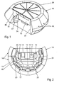
- the exercise simulator for training truck drivers in the guidance of trucks which can be seen in section in FIG. 1 in a perspective representation and in FIG. 2, as an exemplary embodiment of a general exercise simulator for training persons in the guidance of any vehicles, has a driver's cab 10. which is simulated in the case of the truck simulator an original cab of a truck.
- the driver and front passenger seats 11 and 12 and the two outer rearview mirrors are denoted by 13 and 14 in the cab 10.
- a projection screen 15 of an image display system 16 is set up, on which a simulated environment visible from the driver's cab 10 is displayed.
- the simulated environment visible on the projection screen 15 is composed of a plurality of individual images which are projected onto the rear side of the projection screen 15 by a plurality of image projectors 17 in a so-called transmitted light or back projection.
- the image display system 16 arranged around the driver's cab 10 further comprises a plurality of individual mounting modules 18 which are circular-segment-shaped are formed so that they can be lined up to form a partially closed cylinder and firmly connected to each other.
- the formation of a fully closed cylinder for displaying a panoramic view is possible.
- the image display system 16 is composed of a total of eight modules 18, each covering a circle segment of 30 °, so that the image display system 16 extends over 240 ° horizontally around the driver's cab 10 around.
- a module 18 is shown schematically in FIG. 3 in a perspective view and in FIG. 4 in a longitudinal section.
- Each module 18 has a box-shaped module housing 19 which contains a holder 20 for the projection screen 15, an image projector 17 arranged in the foot area and a deflection mirror 21 which folds the projection beam of the image projector 17.
- Image projector 17 and deflecting mirror 21 are arranged within the module housing 19 so that an incident along the projector axis projection beam from the deflecting mirror 21 is reflected so that it impinges at right angles to the projection screen 15.
- Each image projector 17 has a housing 23 containing three color picture tubes 22 and a housing 24 containing the electronics, which is arranged in front of the module 18 between the picture tube housing 23 and the projection screen 15 in order to maximize the free space for the projection beams.
- the picture tubes 22 are rotated so that when horizontal position of the housing 23, a vertical image is projected.
- the image projectors 17 are equipped with a wide-angle lens that provides a ratio of the long image width to the projection distance of 1: 1.2 or greater.
- each holder 20 consists of an upper and lower retaining ring 201 and 202, (FIG. 4), which overlap each with a receptacle 28, the transmitted-light disk 25 at the upper and lower edge of the disc.
- the modules 18 receive at their upper edge a cover 29 (Fig. 1) which is formed so that it spans the remaining between the modules 18 interior space.
- the modular design of the image display system 16 makes it possible to use the exercise simulator for different types of vehicles, e.g. As trucks, trams, locomotives, railcars, etc., and thereby easily adjust the image display system 16 to the required in the respective vehicle field of view from the driver's cab. So z. B. for a truck a field of view of vertically 30 ° down and 10 ° upwards required and horizontal 120 ° to the left and 90 ° to the right. For a tram, however, a field of view must have a viewing angle of vertically each 27 ° up and down and a viewing angle in the horizontal of about 105 ° to the right and left.
- vehicles e.g. As trucks, trams, locomotives, railcars, etc.
- the horizontal field of view can be increased or decreased by adding or removing one or more modules 18, wherein the transparent translucent lens 25 must be replaced by a longer or shorter disc.
- the vertical field of view can be increased by reducing the cylinder radius of the transmitted light disk 25. This is achieved - as illustrated in Fig. 4 - achieved in that the brackets 20 are formed on the modules 18 in the radial direction gradually adjustable. In the embodiment, this can be attached to the module 18 upper and lower adapter 26, 27 and 26 ', 27' are provided, the same receptacles 28 for the upper and lower disc edge as the retaining rings 201 and 202 on the module housing 19.
- the transmitted light disk 25 To reduce the cylinder radius the transmitted light disk 25, these adapters 26, 27 and 26 ', 27' attached to the top and bottom of the module housing 19, and the transmitted-light disk 25 is inserted into the receptacles 28.
- the ⁇ 1 , ⁇ 2 and ⁇ 3 designate the vertical angles of the various fields of view, which are displayed on the translucent lens 25 at a cylinder radius R 1 , R 2 and R 3 of the translucent lens 25.
- the modules 18 are arranged on a circular arc with a larger radius by being deducted from each other and are used in the gaps between them not shown here adapter pieces that connect the adjacent modules 18 together. However, this also increases the outer diameter of the entire exercise simulator.
Landscapes
- Engineering & Computer Science (AREA)
- Theoretical Computer Science (AREA)
- Aviation & Aerospace Engineering (AREA)
- Business, Economics & Management (AREA)
- Physics & Mathematics (AREA)
- Educational Administration (AREA)
- Educational Technology (AREA)
- General Physics & Mathematics (AREA)
- Projection Apparatus (AREA)
- Gyroscopes (AREA)
- Steroid Compounds (AREA)
- Lenses (AREA)
Description
- Die Erfindung betrifft einen Übungssimulator zum Trainieren von Personen in der Führung von Fahrzeugen, insbesondere von Nutzfahrzeugen, der im Oberbegriff des Patentanspruchs 1 angegebenen Gattung.
- Bei einem bekannten Übungssimulator für Lastkraftwagen der eingangs genannten Art, auch Fahrsimulator genannt (DE 39 25 427 A1) ist der Projektionsschirm aus ebenen Einzelflächen zusammengesetzt, die längs eines die Fahrerkabine von vorn umfassenden Polygonzugs lückenlos aneinander anschließen. Die Einzelflächen werden mittels eines Gestells gehalten, das aus einem vertikalen Haltemast und einer auf dem Boden horizontal gelagerten Führungsschiene besteht. Die Bildprojektoren, die jeweils eine Einzelfläche des Projektionsschirms beleuchten, sind in zwei Gruppen aufgeteilt. Die Bildprojektoren für die mittleren Einzelflächen sind in scheinbarer Fahrtrichtung gesehen hinter dem Projektionsschirm angeordnet. Die von diesen Projektoren ausgehenden Lichtbündel treffen durch in den Einzelflächen angeordneten Durchtrittsöffnungen auf den Durchtrittsöffnungen zugeordnete Umlenkspiegel und fallen auf den Projektionsschirm vor der Fahrerkabine. Die Bildprojektoren für die weiter außen liegenden Einzelflächen sind oberhalb der Fahrerkabine angeordnet und ihre Lichtbündel fallen über auf dem Dach der Fahrerkabine befestigte Umlenkspiegel auf den Projektionsschirm. Diese Auflichtprojektion hat den Nachteil, daß bei Verwendung einer üblicherweise geforderten, originalen Fahrerkabine und der Anpassung der simulierten Umwelt an das Sichtfeld des Fahrers wegen den großen Abmessungen der Fahrerkabine und den extremen Abmessungen des Sichtfeldes eine schattenwurffreie Projektion nur dann erreicht werden kann, wenn der Projektionsschirm weit von der Fahrerkabine entfernt ist und die Projektoren hoch über der Fahrerkabine angeordnet werden. Dies bedingt große Abmessungen des Fahrsimulators, was einerseits hohe Gebäude zu dessen Unterbringung erfordert und andererseits auch die Unterbringung des Simulators auf einem Bewegungssystem, z.B. zur Beschleunigungssimulation, erheblich erschwert.
- Bei einem ebenfalls bekannten Fahrsimulator dieser Art (EP 0 709 815 B1) sind für die Darstellung der simulierten Umwelt drei Großbildprojektoren vorgesehen, die mittels Durchlichtprojektion Abschnitte des sichtbaren Panoramas auf jeweils einem von drei trapezförmig vor der Fahrerkabine aufgestellten, transparenten Projektionsschirmen darstellen. Die Großbildprojektoren sind auf der von der Fahrerkabine abgewandten Rückseite der Projektionsschirme angeordnet und jeder Großbildprojektor projiziert über einen Umlenkspiegel einen Sektor eines sich über 180° erstreckenden Panoramas auf die Rückseite des Projektionsschirms.
- Dieses sog. Durchlicht- oder Rückprojektion hat den Vorteil, daß die Lichtwege für die Bilderzeugung und die Bildwahrnehmung strikt getrennt sind und dadurch der Projektionsschirm näher an die Fahrerkabine herangeführt werden kann, was zu kleineren Abmessungen des Simulators und zu helleren Bildern führt. Nachteilig ist, daß die Projektionsschirme relativ instabil sind und sich ebenfalls nicht zur Montage auf einem Bewegungssystem eignen.
- Der Erfindung liegt die Aufgabe zugrunde, einen Übungssimulator der eingangs genannten Art mit geringer Bauhöhe und geringer Baubreite zu schaffen, bei dem ohne nennenswerte konstruktive Änderungen an die Fahrzeugart angepaßte unterschiedliche Sichtfelder auf dem Projektionsschirm entworfen werden können und das Bilddarstellungssystem eine hohe mechanische Stabilität aufweist, so daß der Simulator, z.B. zur Beschleunigungssimulation, auch auf einem Bewegungssystem installiert werden kann.
- Die Aufgabe ist erfindungsgemäß durch die Merkmale im Kennzeichenteil des Anspruchs 1 gelöst.
- Der erfindungsgemäße Übungssimulator hat den Vorteil, daß durch die einstückige, durch Einspannen in den Halterungen zylindrisch gekrümmte, transparente Kunststoff-Durchlichtscheibe der Projektionsschirm eine hohe Stabilität besitzt, die selbst den Anforderungen bei Installation auf einen Bewegungssystem genügt. Durch die Beibehaltung der Durchlichtprojektion ist die strikte Trennung der Lichtwege für die Bilderzeugung und -wahrnehmung gegeben, so daß einerseits die Durchlichtscheibe relativ nahe vor der Fahrerkabine angeordnet werden kann und andererseits die Bildprojektoren nahe dem Boden angeordnet werden können und dadurch insgesamt kleine Abmessungen für den Übungssimulator erzielbar sind. Durch einfaches Verändern des Abstandes der Durchlichtscheibe von den Bildprojektoren läßt sich das Sichtfeld in dem erforderlichen Umfang an das für das jeweilige Übungsfahrzeug geforderte Sichtfeld anpassen. Die Durchlichtscheibe stellt keine besondere Anforderung an Herstellung und Transport, da sie eben ist und erst bei ihrer Montage gekrümmt wird. Die Montage ist einfach und wenig zeitaufwendig, da sie nur in die auf einem Kreisbogen angeordneten Halterungen eingesetzt werden muß, welche die Durchlichtscheibe an deren oberem und unterem Rand einspannen.
- Zweckmäßige Ausführungsformen des erfindungsgemäßen Übungssimulators mit vorteilhaften Weiterbildungen und Ausgestaltungen der Erfindung ergeben sich aus den weiteren Ansprüchen.
- Gemäß einer vorteilhaften Ausführungsform der Erfindung ist jede Halterung an einem Montagemodul ausgebildet, und die Module sind kreissegmentförmig so ausgebildet, daß sie zur Bildung eines teil- oder vollgeschlossenen Zylinders aneinander reihbar und miteinander fest verbindbar sind. Diese Modulbauweise bietet die Möglichkeit, durch einfaches Hinzufügen oder Wegnehmen von Modulen den Projektionsschirm in Horizontalrichtung an das für den speziellen Simulator geforderte Sichtfeld anzupassen. Die Größe der Durchlichtscheibe in Horizontalrichtung muß dabei jeweils dem Sichtfeld entsprechend bemessen werden, was durch Austausch von Durchlichtscheiben erfolgt. Die Module werden bevorzugt so ausgeführt, daß jedes Modul ein Kreissegment von 30° abdeckt, wobei sich die Module über die gesamte vertikale Höhe der Durchlichtscheibe erstrecken und die Halterung an jedem Modul die Durchlichtscheibe an deren oberem und unterem Rand einspannt. Die Module sind dabei so konstruiert, daß sie sowohl alleinstehend als auch auf einem Bewegungssystem montiert werden können.
- Gemäß einer bevorzugten Ausführungsform der Erfindung ist in jedem Modul ein Bildprojektor und ein Umlenkspiegel zur Faltung des von dem Projektor ausgehenden Projektionsstrahls angeordnet, wobei Bildprojektor und Umlenkspiegel so ausgerichtet sind, daß ein längs der Projektorachse einfallender Strahl vom Umlenkspiegel so reflektiert wird, daß er rechtwinklig auf die Durchlichtscheibe auftrifft. Jeder Bildprojektor leuchtet dabei ein Feld von 33° in Horizontalrichtung auf der Durchlichtscheibe aus, um bei einer Segmentbreite von 30° ein sog. Edge Blending, d. h. einen allmählichen Übergang von einem zum anderen Feld, zu erhalten. Mit horizontaler Vergrößerung oder Verkleinerung der Durchlichtscheibe wird damit gleichzeitig die Zahl der erforderlichen Projektoren automatisch angepaßt. Da der Projektionsstrahl senkrecht auf die Durchlichtscheibe trifft, sind keinerlei Trapezkorrekturen erforderlich.
- Gemäß einer vorteilhaften Ausführungsform der Erfindung ist die Halterung der Durchlichtscheibe an jedem Modul radial verstellbar ausgebildet, wobei jede Halterung bevorzugt durch oben und unten an das Modul ansetzbare, jeweils eine Aufnahme für die Durchlichtscheibe tragende Adapter unterschiedlicher Länge in Radialrichtung stufenweise verlängerbar ist. Mittels der Adapter kann der Zylinderradius der Durchlichtscheibe entsprechend der gewählten Länge der Adapter verringert werden, wodurch sich das vertikale Sichtfeld für den Fahrer in der Fahrerkabine erhöht. Die Verringerung des Zylinderradius liefert gleichzeitig den zusätzlich erforderlichen Projektionsabstand, so daß der Außendurchmesser des Bilddarstellungssystems konstant bleibt.
- Aufgrund der Modulbauweise kann für den Einsatz von großen Übungsfahrzeugen auch ein größerer Zylinderradius realisiert werden, indem die Module auseinandergezogen und über in die entstehenden Zwischenräumen eingebrachte Adapter aneinander befestigt werden. Die Module bleiben unverändert, allerdings erhöht sich der Außendurchmesser des Bilddarstellungssystems.
- Gemäß einer vorteilhaften Ausführungsform der Erfindung sind die Bildprojektoren mit einem Weitwinkelobjektiv ausgestattet, das ein Verhältnis der langen Bildseite zum Projektionsabstand von 1:1,2 oder größer liefert. Damit kann der durch die Umlenkspiegel bereits kurze Projektionsabstand zwischen Bildprojektor und Projektionsschirm weiter verkürzt werden, was sich vorteilhaft auf den Außendurchmesser des Bilddarstellungssystems auswirkt.
- Gemäß einer vorteilhaften Ausführungsform der Erfindung sind die Bildröhren jedes Bildprojektors so gedreht, daß bei horizontaler Projektorlage ein vertikal aufgerichtetes Bild projiziert wird. Damit erhält man eine recht flache Bauweise der Bildprojektoren, so daß möglichst viel freier Raum in dem Bereich, in dem die Lichtstrahlen verlaufen, erhalten wird.
- Aus gleichem Grund weist auch jeder Bildprojektor ein die Bildröhren enthaltendes Gehäuse und ein die Elektronik enthaltendes Gehäuse auf, wobei das Elektronikgehäuse außerhalb des von der Durchlichtscheibe und dem Umlenkspiegel begrenzten Raums angeordnet ist.
- Gemäß einer vorteilhaften Ausführungsform der Erfindung nehmen die kreisförmig angeordneten Module an ihrer Oberkante eine Abdeckung auf, die den zwischen den Modulen verbleibenden Raum überspannt. Damit wird eine Kapselung des gesamten Übungssimulators erreicht, so daß es nicht erforderlich ist, den Aufstellungsraum des Übungssimulators abzudunkeln.
- Die Erfindung ist anhand eines in der Zeichnung dargestellten Ausführungsbeispiels im folgenden näher beschrieben. Es zeigen jeweils in schematischer Darstellung:
- Fig. 1
- eine perspektivische Ansicht eines Übungssimulators zum Trainieren von Fahrern von Nutzfahrzeugen, kurz Fahrsimulator genannt,
- Fig. 2
- einen Querschnitt des Fahrsimulators in Figur 1,
- Fig. 3
- eine perspektivische Ansicht eines Moduls des Fahrsimulators in Fig. 1 und 2,
- Fig. 4
- eine Seitenansicht des Moduls in Fig. 3 mit angesetzten Adaptern zur Veränderung des Zylinderradius des Projektionsschirms.
- Der in Fig. 1 in perspektivischer Darstellung und in Fig. 2 im Schnitt zu sehende Übungssimulator zum Trainieren von Lastkraftwagenfahrern in der Führung von Lastkraftwagen, als Ausführungsbeispiel für einen allgemeinen Übungssimulator zum Trainieren von Personen in der Führung beliebiger Fahrzeuge, weist eine Fahrerkabine 10 auf, die im Falle des Lastkraftwagensimulators einem originalen Fahrerhaus eines Lastkraftwagens nachgebildet ist. In Fig. 2 sind in der Fahrerkabine 10 der Fahrer- und Beifahrersitz mit 11 und 12 und die beiden äußeren Rückblickspiegel mit 13 und 14 bezeichnet. Vor der Fahrerkabine 10 ist ein Projektionsschirm 15 eines Bilddarstellungssystems 16 aufgestellt, auf dem eine von der Fahrerkabine 10 aus sichtbare simulierte Umwelt dargestellt wird. Wie bekannt ist die auf dem Projektionsschirm 15 sichtbare simulierte Umwelt aus einer Mehrzahl von Einzelbildern zusammengesetzt, die von einer Mehrzahl von Bildprojektoren 17 in einer sog. Durchlicht- oder Rückprojektion auf die Rückseite des Projektionsschirm 15 projiziert werden.
- Das um die Fahrerkabine 10 herum angeordnete Bilddarstellungssystem 16 umfaßt weiterhin eine Mehrzahl von einzelnen Montagemodulen 18, die kreissegmentförmig so ausgebildet sind, daß sie zur Bildung eines teilgeschlossenen Zylinders aneinanderreihbar sind und fest miteinander verbunden werden. Die Bildung eines vollgeschlossenen Zylinders zur Darstellung einer Rundumsicht ist möglich. Im Ausführungsbeispiel ist das Bilddarstellungssystem 16 aus insgesamt acht Modulen 18 zusammengesetzt, die jeweils ein Kreissegment von 30° abdecken, so daß sich das Bilddarstellungssystem 16 insgesamt über 240° horizontal um die Fahrerkabine 10 herum erstreckt. Ein Modul 18 ist in Fig. 3 in perspektivischer Ansicht und in Fig. 4 im Längsschnitt jeweils schematisch dargestellt. Jedes Modul 18 weist ein kastenförmiges Modulgehäuse 19 auf, das eine Halterung 20 für den Projektionsschirm 15, einen im Fußbereich angeordneten Bildprojektor 17 und einen Umlenkspiegel 21 enthält, der den Projektionsstrahl des Bildprojektors 17 faltet. Bildprojektor 17 und Umlenkspiegel 21 sind innerhalb des Modulgehäuses 19 so angeordnet, daß ein längs der Projektorachse einfallender Projektionsstrahl vom Umlenkspiegel 21 so reflektiert wird, daß er rechtwinklig auf den Projektionsschirm 15 auftrifft. Jeder Bildprojektor 17 weist ein drei Farb-Bildröhren 22 enthaltendes Gehäuse 23 und ein die Elektronik enthaltendes Gehäuse 24 auf, das zur Erzielung eines möglichst großen Freiraums für die Projektionsstrahlen zwischen den Bildröhren-Gehäuse 23 und dem Projektionsschirm 15 vor dem Modul 18 angeordnet ist. Um eine möglichst flache Bauweise des die Bildröhren 22 aufnehmenden Gehäuses 23 zu erreichen, sind die Bildröhren 22 so gedreht, daß bei waagerechter Lage des Gehäuses 23 ein senkrecht stehendes Bild projiziert wird. Zur Verkürzung des Projektionsabstands sind die Bildprojektoren 17 mit einem Weitwinkelobjektiv ausgestattet, das ein Verhältnis der langen Bildbreite zum Projektionsabstand von 1:1,2 oder größer liefert.
- Als Projektionsschirm 15 wird eine einstückige, ebene Durchlichtscheibe 25 aus transparentem Kunststoff verwendet, die in die Halterungen 20 in den einzelnen Modulen 18 eingespannt und dadurch zylindrisch gekrümmt wird. Hierzu besteht jede Halterung 20 aus einem oberen und unteren Haltering 201 und 202, (Fig. 4), der mit jeweils einer Aufnahme 28 die Durchlichtscheibe 25 an deren oberem und unterem Scheibenrand übergreifen. Außerdem nehmen die Module 18 an ihrer Oberkante eine Abdeckung 29 (Fig. 1) auf, die so ausgebildet ist, daß sie den zwischen den Modulen 18 verbleibenden Innenraum überspannt. Damit ist eine Gesamtkapselung des Übungssimulators gegeben, so daß bei Betrieb des Übungssimulators der Aufstellraum nicht abgedunkelt werden muß.
- Die Modulbauweise des Bilddarstellungssystems 16 ermöglicht es, den Übungssimulator für verschiedene Fahrzeugarten, z. B. Lastkraftwagen, Straßenbahnen, Lokomotiven, Triebwagen etc., zu verwenden und dabei in einfacher Weise das Bilddarstellungssystem 16 an das bei dem jeweiligen Fahrzeug geforderte Sichtfeld aus dem Fahrerstand heraus anzupassen. So ist z. B. für einen Lastkraftwagen ein Sichtfeld von vertikal 30° nach unten und 10° nach oben gefordert sowie horizontal 120° nach links und 90° nach rechts. Für eine Straßenbahn dagegen muß ein Sichtfeld einen Sichtwinkel von vertikal jeweils 27° nach oben und unten und einen Sichtwinkel in der Horizontalen von ca. 105° nach rechts und links aufweisen. Das horizontale Sichtfeld läßt sich durch Hinzufügen oder Wegnehmen eines oder mehrerer Module 18 vergrößern oder verringern, wobei die transparente Durchlichtscheibe 25 durch eine längere oder kürzere Scheibe ersetzt werden muß. Das vertikale Sichtfeld läßt sich vergrößern, indem der Zylinderradius der Durchlichtscheibe 25 verkleinert wird. Dies wird - wie in Fig. 4 illustriert ist - dadurch erreicht, daß die Halterungen 20 an den Modulen 18 in Radialrichtung stufenweise verstellbar ausgebildet sind. Im Ausführungsbeispiel sind hierzu an das Modul 18 ansetzbare obere und untere Adapter 26, 27 bzw. 26', 27' vorgesehen, die gleiche Aufnahmen 28 für den oberen und unteren Scheibenrand aufweisen wie die Halteringe 201 und 202 am Modulgehäuse 19. Zum Verkleinern des Zylinderradius der Durchlichtscheibe 25 werden diese Adapter 26, 27 bzw. 26', 27' oben und unten an dem Modulgehäuse 19 befestigt, und die Durchlichtscheibe 25 wird in die Aufnahmen 28 eingesetzt. In Fig. 4 sind mit den α1, α2 und α3 die Vertikalwinkel der verschiedenen Sichtfelder bezeichnet, die auf der Durchlichtscheibe 25 bei einem Zylinderradius R1, R2 und R3 der Durchlichtscheibe 25 dargestellt werden.
- Wenn in einem speziellen Anwendungsfall eine Vergrößerung des Zylinderradius der Durchlichtscheibe 25 gewünscht wird, um beispielsweise ein großes Übungsfahrzeug einzusetzen, so ist dies ebenfalls möglich. Hierzu werden die Module 18 auf einem Kreisbogen mit größerem Radius angeordnet, indem sie von einander abgezogen werden und in den zwischen ihnen entstehenden Lücken hier nicht dargestellte Adapterstücke eingesetzt werden, die die benachbarten Module 18 fest miteinander verbinden. Dadurch vergrößert sich allerdings auch der Außendurchmesser des gesamten Übungssimulators.
Claims (12)
- Übungssimulator zum Trainieren von Personen in der Führung von Fahrzeugen, insbesondere von Nutzfahrzeugen, mit einer Fahrerkabine (10) und mit einem Bilddarstellungssystem (16) zur Erzeugung einer von der Fahrerkabine (10) aus sichtbaren, simulierten Umwelt, das einen vor der Fahrerkabine (10) aufgestellten Projektionsschirm (15) und mehrere Bildprojektoren (17) zur Projektion von die simulierte Umwelt zusammensetzenden Bildern auf die von der Fahrerkabine (10) abgekehrte Rückseite des Projektionsschirms (15) aufweist, dadurch gekennzeichnet, daß der Projektionsschirm (15) eine einstückige, ebene Durchlichtscheibe (25) aus transparentem Kunststoff ist, die mittels auf einem Kreisbogen festgelegter Halterungen (20) zylindrisch gekrümmt ist.
- Simulator nach Anspruch 1, dadurch gekennzeichnet, daß jede Halterung (20) an einem Montagemodul (18) ausgebildet ist und daß die Module (18) kreissegmentförmig so ausgebildet sind, daß sie zur Bildung eines teil- oder vollgeschlossenen Zylinders aneinander reihbar und miteinander fest verbindbar sind.
- Simulator nach Anspruch 2, dadurch gekennzeichnet, daß das Modul (18) sich über die gesamte vertikale Höhe der Durchlichtscheibe (25) erstreckt und die Halterungen (20) die Durchlichtscheibe (25) längs deren oberen und unteren Scheibenrand einspannen.
- Simulator nach Anspruch 3, dadurch gekennzeichnet, daß jede Halterung (20) eines Moduls (18) zwei die Durchlichtscheibe (25) an deren oberem und unterem Scheibenrand übergreifende Halteringe (201, 202) aufweist.
- Simulator nach einem der Ansprüche 2 bis 4, dadurch gekennzeichnet, daß jedes Modul (18) ein Kreissegment von 30° abdeckt.
- Simulator nach einem der Ansprüche 2 bis 5, dadurch gekennzeichnet, daß die Halterung (20) für die Durchlichtscheibe (25) an jedem Modul (18) radial, vorzugsweise in Stufen verstellbar, ausgebildet ist.
- Simulator nach Anspruch 6, dadurch gekennzeichnet, daß jede Halterung (20) durch oben und unten an das Modul (18) ansetzbare, jeweils eine Aufnahme (28) für die Durchlichtscheibe (25) aufweisende Adapter (26, 27; 26', 27') unterschiedlicher Länge in Radialrichtung stufenweise verlängerbar ist.
- Simulator nach einem der Ansprüche 1 bis 7, dadurch gekennzeichnet, daß in jedem Modul (18) ein Bildprojektor (17) und ein Umlenkspiegel (21) zur Faltung des von dem Bildprojektor (17) ausgehenden Projektionsstrahls angeordnet ist und daß Bildprojektor (17) und Umlenkspiegel (21) so ausgerichtet sind, daß ein längs der Projektorachse einfallender Projektionsstrahl vom Umlenkspiegel (21) so reflektiert wird, daß er rechtwinklig auf die Durchlichtscheibe (25) auftrifft.
- Simulator nach einem der Ansprüche 1 bis 8, dadurch gekennzeichnet, daß die Bildprojektoren (17) mit einem Weitwinkelobjektiv ausgestattet sind, das ein Verhältnis der langen Bildseite zum Projektionsabstand von 1:1,2 liefert.
- Simulator nach Anspruch 8 oder 9, dadurch gekennzeichnet, daß die Bildröhren (22) der Bildprojektoren (17) so gedreht sind, daß bei horizontaler Projektorlage ein vertikal aufgerichtetes Bild projiziert wird.
- Simulator nach einem der Ansprüche 1 bis 10, dadurch gekennzeichnet, daß jeder Bildprojektor (17) ein die Bildröhren (22) enthaltendes Gehäuse (23) und ein die Elektronik enthaltendes Gehäuse (24) aufweist und daß das Elektronikgehäuse (24) außerhalb des im Modul (18) von der Durchlichtscheibe (25) und dem Umlenkspiegel (21) begrenzten Raums angeordnet ist.
- Simulator nach einem der Ansprüche 2 bis 11, dadurch gekennzeichnet, daß die kreisförmig aneinandergereihten Module (18) an ihrer Oberkannte eine Abdeckung (29) aufnehmen, die den von den Modulen (18) umgrenzten Innenraum überspannt.
Applications Claiming Priority (2)
| Application Number | Priority Date | Filing Date | Title |
|---|---|---|---|
| DE19850406A DE19850406C1 (de) | 1998-11-02 | 1998-11-02 | Übungssimulator |
| DE19850406 | 1998-11-02 |
Publications (3)
| Publication Number | Publication Date |
|---|---|
| EP0999534A2 EP0999534A2 (de) | 2000-05-10 |
| EP0999534A3 EP0999534A3 (de) | 2006-01-11 |
| EP0999534B1 true EP0999534B1 (de) | 2007-02-28 |
Family
ID=7886379
Family Applications (1)
| Application Number | Title | Priority Date | Filing Date |
|---|---|---|---|
| EP99118219A Expired - Lifetime EP0999534B1 (de) | 1998-11-02 | 1999-09-14 | Übungssimulator |
Country Status (3)
| Country | Link |
|---|---|
| EP (1) | EP0999534B1 (de) |
| AT (1) | ATE355580T1 (de) |
| DE (2) | DE19850406C1 (de) |
Families Citing this family (2)
| Publication number | Priority date | Publication date | Assignee | Title |
|---|---|---|---|---|
| DE10302409A1 (de) * | 2003-01-21 | 2004-08-05 | Rheinmetall Defence Electronics Gmbh | Verfahren zur Bilddarstellung |
| US7708561B2 (en) | 2005-09-23 | 2010-05-04 | Q4 Services Llc | Method and apparatus for modifying aircraft simulator wide-angled infinity display equipment mirror to enlarge field of vision and for reskinning aircraft simulator spherical mirror cell to minimize mirror stress and distortion |
Family Cites Families (5)
| Publication number | Priority date | Publication date | Assignee | Title |
|---|---|---|---|---|
| FR2636459B1 (fr) * | 1988-09-09 | 1990-10-19 | Thomson Csf | Systeme de restitution de l'environnement visuel d'un pilote en simulateur |
| DE3925427C2 (de) * | 1989-08-01 | 2000-01-13 | Wegmann & Co Gmbh | Fahrsimulator, insbesondere zur Ausbildung an Lastkraftwagen |
| DE4438411A1 (de) * | 1994-10-27 | 1996-05-02 | Stn Atlas Elektronik Gmbh | Übungseinrichtung |
| JPH08248872A (ja) * | 1995-03-08 | 1996-09-27 | Toyota Motor Corp | 運転模擬試験装置 |
| JP2781755B2 (ja) * | 1995-10-04 | 1998-07-30 | 東芝テスコ株式会社 | 乗物シミュレータ用ドームスクリーン |
-
1998
- 1998-11-02 DE DE19850406A patent/DE19850406C1/de not_active Expired - Fee Related
-
1999
- 1999-09-14 DE DE59914219T patent/DE59914219D1/de not_active Expired - Lifetime
- 1999-09-14 EP EP99118219A patent/EP0999534B1/de not_active Expired - Lifetime
- 1999-09-14 AT AT99118219T patent/ATE355580T1/de not_active IP Right Cessation
Also Published As
| Publication number | Publication date |
|---|---|
| ATE355580T1 (de) | 2006-03-15 |
| DE59914219D1 (de) | 2007-04-12 |
| EP0999534A3 (de) | 2006-01-11 |
| EP0999534A2 (de) | 2000-05-10 |
| DE19850406C1 (de) | 2000-01-13 |
Similar Documents
| Publication | Publication Date | Title |
|---|---|---|
| DE19851000C2 (de) | Projektionsanordnung | |
| WO1988008146A1 (en) | Stereoscopic display system | |
| EP3834031B1 (de) | Verfahren zum betreiben einer blickfeldanzeigevorrichtung für ein kraftfahrzeug | |
| WO2019238846A1 (de) | Head-up-display für ein fahrzeug | |
| DE19626096C1 (de) | Verfahren zur dreidimensionalen Bilddarstellung auf einer Großbildprojektionsfläche mittels eines Laser-Projektors | |
| EP0356891A2 (de) | Umschaltbarer Winkelspiegel für Periskope | |
| DE2009200A1 (de) | Anzeigevorrichtung zur Wiedergabe von relativ zueinander bewegbaren Symbolen | |
| EP0999534B1 (de) | Übungssimulator | |
| DE102018200498A1 (de) | Anzeigevorrichtung und Verfahren zur Projizierung eines Bildes auf eine virtuelle Position während einer Fahrt eines Fahrzeuges | |
| DE102019127406A1 (de) | Kraftfahrzeug mit einer Umfeldbeleuchtungseinrichtung | |
| DE3925427C2 (de) | Fahrsimulator, insbesondere zur Ausbildung an Lastkraftwagen | |
| DE102019108330A1 (de) | Faltbare Blickfeldanzeigevorrichtung | |
| DE202006020591U1 (de) | Head-Up-Display-System für Kraftfahrzeuge | |
| EP3655812A1 (de) | Projektionsanzeigevorrichtung mit einer darstellung in mehreren anzeigenebenen | |
| DE102017216525A1 (de) | Head-up-Anzeigevorrichtung für ein Kraftfahrzeug | |
| DE19907345B4 (de) | Vorrichtung zum Abbilden eines als Raster von Bildpunkten darstellbaren Bildes auf einem Schirm | |
| DE112019002608T5 (de) | Head-up-Display-Vorrichtung | |
| DE102019122417A1 (de) | Kompakte Blickfeldanzeigevorrichtung | |
| DE102018204958B4 (de) | Anzeigeeinrichtung zur Projektion eines Bilds auf eine Scheibe eines Kraftfahrzeugs sowie Verfahren zum Betreiben einer Anzeigeeinrichtung | |
| DE4103845A1 (de) | Projektionsvorrichtung fuer planetarien | |
| DE102023105899A1 (de) | Head-Up-Display mit einer platzsparenden Displayanordnung, insbesondere für ein Fahrzeug | |
| DE829433C (de) | Scheinwerfer fuer Fahrzeuge, insbesondere Kraftfahrzeuge | |
| DE102021116304A1 (de) | Anzeigevorrichtung und Kraftfahrzeug mit derartiger Anzeigevorrichtung | |
| WO2003062918A1 (de) | Projektionsanordnung mit zugehörigem raum zur kuppelprojektion | |
| DE974125C (de) | Projektionsapparate, insbesondere Mikroablesegeraete |
Legal Events
| Date | Code | Title | Description |
|---|---|---|---|
| PUAI | Public reference made under article 153(3) epc to a published international application that has entered the european phase |
Free format text: ORIGINAL CODE: 0009012 |
|
| AK | Designated contracting states |
Kind code of ref document: A2 Designated state(s): AT BE CH CY DE DK ES FI FR GB GR IE IT LI LU MC NL PT SE |
|
| AX | Request for extension of the european patent |
Free format text: AL;LT;LV;MK;RO;SI |
|
| RAP1 | Party data changed (applicant data changed or rights of an application transferred) |
Owner name: RHEINMETALL DEFENCE ELECTRONICS GMBH |
|
| PUAL | Search report despatched |
Free format text: ORIGINAL CODE: 0009013 |
|
| AK | Designated contracting states |
Kind code of ref document: A3 Designated state(s): AT BE CH CY DE DK ES FI FR GB GR IE IT LI LU MC NL PT SE |
|
| AX | Request for extension of the european patent |
Extension state: AL LT LV MK RO SI |
|
| 17P | Request for examination filed |
Effective date: 20060616 |
|
| AKX | Designation fees paid |
Designated state(s): AT BE CH CY DE DK ES FI FR GB GR IE IT LI LU MC NL PT SE |
|
| GRAP | Despatch of communication of intention to grant a patent |
Free format text: ORIGINAL CODE: EPIDOSNIGR1 |
|
| GRAS | Grant fee paid |
Free format text: ORIGINAL CODE: EPIDOSNIGR3 |
|
| GRAA | (expected) grant |
Free format text: ORIGINAL CODE: 0009210 |
|
| AK | Designated contracting states |
Kind code of ref document: B1 Designated state(s): AT BE CH CY DE DK ES FI FR GB GR IE IT LI LU MC NL PT SE |
|
| PG25 | Lapsed in a contracting state [announced via postgrant information from national office to epo] |
Ref country code: IE Free format text: LAPSE BECAUSE OF FAILURE TO SUBMIT A TRANSLATION OF THE DESCRIPTION OR TO PAY THE FEE WITHIN THE PRESCRIBED TIME-LIMIT Effective date: 20070228 Ref country code: FI Free format text: LAPSE BECAUSE OF FAILURE TO SUBMIT A TRANSLATION OF THE DESCRIPTION OR TO PAY THE FEE WITHIN THE PRESCRIBED TIME-LIMIT Effective date: 20070228 Ref country code: DK Free format text: LAPSE BECAUSE OF FAILURE TO SUBMIT A TRANSLATION OF THE DESCRIPTION OR TO PAY THE FEE WITHIN THE PRESCRIBED TIME-LIMIT Effective date: 20070228 |
|
| REG | Reference to a national code |
Ref country code: GB Ref legal event code: FG4D Free format text: NOT ENGLISH |
|
| REG | Reference to a national code |
Ref country code: CH Ref legal event code: EP |
|
| REF | Corresponds to: |
Ref document number: 59914219 Country of ref document: DE Date of ref document: 20070412 Kind code of ref document: P |
|
| REG | Reference to a national code |
Ref country code: IE Ref legal event code: FG4D Free format text: LANGUAGE OF EP DOCUMENT: GERMAN |
|
| PG25 | Lapsed in a contracting state [announced via postgrant information from national office to epo] |
Ref country code: SE Free format text: LAPSE BECAUSE OF FAILURE TO SUBMIT A TRANSLATION OF THE DESCRIPTION OR TO PAY THE FEE WITHIN THE PRESCRIBED TIME-LIMIT Effective date: 20070531 |
|
| REG | Reference to a national code |
Ref country code: CH Ref legal event code: NV Representative=s name: TROESCH SCHEIDEGGER WERNER AG |
|
| PG25 | Lapsed in a contracting state [announced via postgrant information from national office to epo] |
Ref country code: ES Free format text: LAPSE BECAUSE OF FAILURE TO SUBMIT A TRANSLATION OF THE DESCRIPTION OR TO PAY THE FEE WITHIN THE PRESCRIBED TIME-LIMIT Effective date: 20070608 |
|
| GBT | Gb: translation of ep patent filed (gb section 77(6)(a)/1977) |
Effective date: 20070522 |
|
| REG | Reference to a national code |
Ref country code: GR Ref legal event code: EP Ref document number: 20070401462 Country of ref document: GR |
|
| PG25 | Lapsed in a contracting state [announced via postgrant information from national office to epo] |
Ref country code: PT Free format text: LAPSE BECAUSE OF FAILURE TO SUBMIT A TRANSLATION OF THE DESCRIPTION OR TO PAY THE FEE WITHIN THE PRESCRIBED TIME-LIMIT Effective date: 20070730 |
|
| ET | Fr: translation filed | ||
| REG | Reference to a national code |
Ref country code: IE Ref legal event code: FD4D |
|
| PLBE | No opposition filed within time limit |
Free format text: ORIGINAL CODE: 0009261 |
|
| STAA | Information on the status of an ep patent application or granted ep patent |
Free format text: STATUS: NO OPPOSITION FILED WITHIN TIME LIMIT |
|
| 26N | No opposition filed |
Effective date: 20071129 |
|
| PG25 | Lapsed in a contracting state [announced via postgrant information from national office to epo] |
Ref country code: MC Free format text: LAPSE BECAUSE OF NON-PAYMENT OF DUE FEES Effective date: 20070930 Ref country code: IT Free format text: LAPSE BECAUSE OF FAILURE TO SUBMIT A TRANSLATION OF THE DESCRIPTION OR TO PAY THE FEE WITHIN THE PRESCRIBED TIME-LIMIT Effective date: 20070228 |
|
| PG25 | Lapsed in a contracting state [announced via postgrant information from national office to epo] |
Ref country code: AT Free format text: LAPSE BECAUSE OF NON-PAYMENT OF DUE FEES Effective date: 20070914 |
|
| PG25 | Lapsed in a contracting state [announced via postgrant information from national office to epo] |
Ref country code: CY Free format text: LAPSE BECAUSE OF FAILURE TO SUBMIT A TRANSLATION OF THE DESCRIPTION OR TO PAY THE FEE WITHIN THE PRESCRIBED TIME-LIMIT Effective date: 20070228 |
|
| PG25 | Lapsed in a contracting state [announced via postgrant information from national office to epo] |
Ref country code: LU Free format text: LAPSE BECAUSE OF NON-PAYMENT OF DUE FEES Effective date: 20070914 |
|
| REG | Reference to a national code |
Ref country code: GB Ref legal event code: 746 Effective date: 20120117 |
|
| REG | Reference to a national code |
Ref country code: DE Ref legal event code: R084 Ref document number: 59914219 Country of ref document: DE Effective date: 20111219 |
|
| PGFP | Annual fee paid to national office [announced via postgrant information from national office to epo] |
Ref country code: GR Payment date: 20120926 Year of fee payment: 14 |
|
| REG | Reference to a national code |
Ref country code: GR Ref legal event code: ML Ref document number: 20070401462 Country of ref document: GR Effective date: 20140403 |
|
| PG25 | Lapsed in a contracting state [announced via postgrant information from national office to epo] |
Ref country code: GR Free format text: LAPSE BECAUSE OF NON-PAYMENT OF DUE FEES Effective date: 20140403 |
|
| REG | Reference to a national code |
Ref country code: FR Ref legal event code: PLFP Year of fee payment: 18 |
|
| PGFP | Annual fee paid to national office [announced via postgrant information from national office to epo] |
Ref country code: NL Payment date: 20160920 Year of fee payment: 18 Ref country code: GB Payment date: 20160920 Year of fee payment: 18 |
|
| PGFP | Annual fee paid to national office [announced via postgrant information from national office to epo] |
Ref country code: BE Payment date: 20160920 Year of fee payment: 18 |
|
| REG | Reference to a national code |
Ref country code: FR Ref legal event code: PLFP Year of fee payment: 19 |
|
| PGFP | Annual fee paid to national office [announced via postgrant information from national office to epo] |
Ref country code: FR Payment date: 20170928 Year of fee payment: 19 Ref country code: CH Payment date: 20170921 Year of fee payment: 19 |
|
| PGFP | Annual fee paid to national office [announced via postgrant information from national office to epo] |
Ref country code: DE Payment date: 20170928 Year of fee payment: 19 |
|
| REG | Reference to a national code |
Ref country code: NL Ref legal event code: MM Effective date: 20171001 |
|
| GBPC | Gb: european patent ceased through non-payment of renewal fee |
Effective date: 20170914 |
|
| REG | Reference to a national code |
Ref country code: BE Ref legal event code: MM Effective date: 20170930 |
|
| PG25 | Lapsed in a contracting state [announced via postgrant information from national office to epo] |
Ref country code: NL Free format text: LAPSE BECAUSE OF NON-PAYMENT OF DUE FEES Effective date: 20171001 |
|
| PG25 | Lapsed in a contracting state [announced via postgrant information from national office to epo] |
Ref country code: GB Free format text: LAPSE BECAUSE OF NON-PAYMENT OF DUE FEES Effective date: 20170914 |
|
| PG25 | Lapsed in a contracting state [announced via postgrant information from national office to epo] |
Ref country code: BE Free format text: LAPSE BECAUSE OF NON-PAYMENT OF DUE FEES Effective date: 20170930 |
|
| REG | Reference to a national code |
Ref country code: DE Ref legal event code: R119 Ref document number: 59914219 Country of ref document: DE |
|
| REG | Reference to a national code |
Ref country code: CH Ref legal event code: PL |
|
| PG25 | Lapsed in a contracting state [announced via postgrant information from national office to epo] |
Ref country code: DE Free format text: LAPSE BECAUSE OF NON-PAYMENT OF DUE FEES Effective date: 20190402 |
|
| PG25 | Lapsed in a contracting state [announced via postgrant information from national office to epo] |
Ref country code: FR Free format text: LAPSE BECAUSE OF NON-PAYMENT OF DUE FEES Effective date: 20180930 Ref country code: CH Free format text: LAPSE BECAUSE OF NON-PAYMENT OF DUE FEES Effective date: 20180930 Ref country code: LI Free format text: LAPSE BECAUSE OF NON-PAYMENT OF DUE FEES Effective date: 20180930 |