EP0999021A2 - Pressure casting line for sanitary articles, and relative mould - Google Patents
Pressure casting line for sanitary articles, and relative mould Download PDFInfo
- Publication number
- EP0999021A2 EP0999021A2 EP99203520A EP99203520A EP0999021A2 EP 0999021 A2 EP0999021 A2 EP 0999021A2 EP 99203520 A EP99203520 A EP 99203520A EP 99203520 A EP99203520 A EP 99203520A EP 0999021 A2 EP0999021 A2 EP 0999021A2
- Authority
- EP
- European Patent Office
- Prior art keywords
- mould
- line
- block
- frame
- support platform
- Prior art date
- Legal status (The legal status is an assumption and is not a legal conclusion. Google has not performed a legal analysis and makes no representation as to the accuracy of the status listed.)
- Withdrawn
Links
Images


Classifications
-
- B—PERFORMING OPERATIONS; TRANSPORTING
- B28—WORKING CEMENT, CLAY, OR STONE
- B28B—SHAPING CLAY OR OTHER CERAMIC COMPOSITIONS; SHAPING SLAG; SHAPING MIXTURES CONTAINING CEMENTITIOUS MATERIAL, e.g. PLASTER
- B28B1/00—Producing shaped prefabricated articles from the material
- B28B1/26—Producing shaped prefabricated articles from the material by slip-casting, i.e. by casting a suspension or dispersion of the material in a liquid-absorbent or porous mould, the liquid being allowed to soak into or pass through the walls of the mould; Moulds therefor ; specially for manufacturing articles starting from a ceramic slip; Moulds therefor
- B28B1/265—Producing shaped prefabricated articles from the material by slip-casting, i.e. by casting a suspension or dispersion of the material in a liquid-absorbent or porous mould, the liquid being allowed to soak into or pass through the walls of the mould; Moulds therefor ; specially for manufacturing articles starting from a ceramic slip; Moulds therefor pressure being applied on the slip in the filled mould or on the moulded article in the mould, e.g. pneumatically, by compressing slip in a closed mould
- B28B1/266—Means for counteracting the pressure being applied on the slip or on the moulded article in the mould, e.g. means for clamping the moulds parts together in a frame-like structure
Definitions
- the invention concerns those machines used in the forming of sanitary articles, in particular water closet pans of wall-mounted type.
- Sanitary articles are formed by casting slip in hygroscopic and/or permeable moulds, which can comprise two or more parts depending on the complexity of the article to be formed.
- Resin moulds have much better mechanical characteristics than plaster moulds, with the result that improved casting techniques have enabled the slip to be fed generally at a pressure of between 3 and 15 bar.
- moulds composed of two parts to form articles of simple configuration such as wash basins or pillars
- machines or so-called casting lines are known in which the mould parts comprising a female part and a male part are mounted in line and mutually slidable.
- these moulds are formed of at least three parts, at least one of which is brought into contact with the others in a direction perpendicular to that in which these latter are brought into mutual contact.
- Casting lines are in fact known comprising a number of individual moulds arranged side by side in parallel.
- Machines for series-casting wall-mounted pans are also known using moulds in four parts which open and close in three mutually perpendicular directions.
- the closure forces between the mould parts can be compensated only partly, namely only in one direction.
- the object of this patent is to enable a forming line for sanitary articles, in particular wall-mounted water closet pans, to be implemented with moulds comprising at least three parts in which the mould closure forces are compensated along the line, to allow light and economical line construction, practically without limit on the number of articles formed simultaneously by it.
- the line is arranged to receive moulds comprising at least three parts.
- moulds comprising two parts, plus a third part which is brought into contact with the other two in a direction perpendicular to that in which these latter are brought into mutual contact.
- the object of the invention is attained in that during casting, the third mould part is securely fixed to the other two by suitable means, such that the closure forces which arise in a direction perpendicular to the line direction are absorbed in each individual mould, whereas the closure forces in the line direction are compensated for all the intermediate moulds.
- the mould 12 is composed of three parts, indicated by the reference numerals 120, 121, 122 respectively, of which two parts, namely the parts 120 and 121, come into mutual contact in the axial direction of the casting line, the third part 122 coming into contact with the other two in a direction perpendicular thereto.
- the part 120 is intended to form the lower part of the wall-mounted pan, the part 121 is intended to form the upper part or rim, and the part 122 is intended to form the lower stench trap and the pan rear to be fixed to the wall.
- the mould 12 is arranged to form two wall-mounted pans, but can be structured to enable a different number of wall-mounted pans to be formed simultaneously, depending on the line production requirements.
- a movable core 110 manually inserted as described hereinafter, cooperates with the part 121.
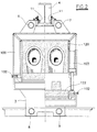
- Figures 1 and 2 show the machine 1 of the invention, comprising two opposing endpieces 2 and 3 upperly supporting, in a central position, a beam 4 of I cross-section. At its ends the beam 4 comprises a flange 5 for fixing to the endpieces 2 and 3 by usual means, such as bolts or the like.
- the two endpieces 2 and 3 are also connected together by four identical tie rods 6, 7, 8, 9, arranged in two parallel rows, as shown in Figure 2.
- the beam 4 is arranged to slidingly support mould blocks each composed of one of the said parts 120 carrying on its rear, ie in the opposite position to that shown in Figure 3, one of the said parts 121.
- Each block 10 is contained within a lowerly open perimetral reinforcement frame, which can be either a single structure or comprise a pair of upperly open frames 100 and 101 respectively.
- the frames 100 and 101 are suspended from the beam 4 slidingly via wheels 11 which enable them to traverse in the direction of the longitudinal axis of the beam 4.
- the third mould part 122 is coupled to a platform composed of three lower beams 105, 106, 107 welded together and arranged to lock onto the frames 100 and 101 when the mould is closed.
- the beams 105, 106, 107 form a single unit and are suspended from the frames 100 and 101 by two identical cylinder-piston units 103 arranged to move these beams together with the respective mould part 122 into a lowered open position distant from the parts 120 and 121, shown to the right of Figure 2, and into a raised closed position, shown to the left of Figure 2.
- suitable adjustable supports 102 cooperate with the cylinder-piston units 103 to lock the beams 105, 106, 107 to the frames 100, 101 to close them in such a manner as to prevent their opening when subjected to the pressure of the slip.
- the endpiece 2 carries a mould part 121 aligned with the suspended mould parts, a large cylinder-piston unit 108 provided with a thrust head 109 being fixed to the endpiece 3 to slide the suspended blocks 10 and press them against that mould part 121 suspended from the endpiece 2.
- the movable core 110 is inserted manually above the mould part 121 to form the stench trap of said water closet pan.
- the invention operates in the following manner.
- Said first block 10 is then moved manually against that mould part 121 fixed to the endpiece 2, after inserting the movable core 110.
- the articles are removed from the moulds by operating in the reverse sense, the formed articles being extracted from the mould part 120 either individually or in pairs, by appropriate usual extractor devices after removing the core 110.
- the blocks 10 will lie all bunched against the thrust head 109 of the cylinder-piston unit 108, which has already been retracted to lie close to the endpiece 3 of the line.
- the machine structure can comprise four beams, namely two lower and two upper, for the said purpose of guiding and supporting the blocks 10.
- Mould opening and closure can also be mechanized.
- the core 110 could be handled mechanically or be made formed integral with the mould piece 121.
Landscapes
- Engineering & Computer Science (AREA)
- Chemical & Material Sciences (AREA)
- Ceramic Engineering (AREA)
- Dispersion Chemistry (AREA)
- Manufacturing & Machinery (AREA)
- Mechanical Engineering (AREA)
- Moulds For Moulding Plastics Or The Like (AREA)
- Producing Shaped Articles From Materials (AREA)
Abstract
Description
Claims (13)
- A line for pressure casting sanitary articles in moulds, comprising a structure from which there are slidingly suspended blocks consisting of two mould parts arranged in opposing positions such that one mould part becomes associated with that other mould part forming part of the adjacent block, and means for bringing the blocks one against the other at one end of the structure and maintaining them locked together in the axial direction, characterised in that each block supports at least one further mould part which can be brought into association with the block in a direction perpendicular to the axis of the structure, means being provided between each block and the respective further mould part to lock said at least one further mould part in its closure position.
- A line as claimed in claim 1, characterised in that each block is contained within a lowerly open frame.
- A line as claimed in claim 1, characterised in that each block is contained within at least two lowerly open parallel frames.
- A line as claimed in claims 2 and 3, characterised in that said frame or said at least two frames support the respective block and are slidingly suspended from the upper frame of the structure.
- A line as claimed in the preceding claims, characterised in that the at least one further mould part is associated with a support platform.
- A line as claimed in claim 5, characterised in that said platform comprises at least two support beams.
- A line as claimed in the preceding claims, characterised in that said support platform is complementary to said open frames, which when in combination with said support platform form closed frames.
- A line as claimed in the preceding claims, characterised in that said support platform is engaged by means arranged to being it into a lowered position in which the mould is open and into a raised position in which the mould is closed.
- A line as claimed in claim 8, characterised in that said means are at least one cylinder-piston unit acting between each open frame and the underlying support platform.
- A line as claimed in the preceding claims, characterised in that adjustable supports are provided to cooperate with said at least one cylinder-piston unit to lock each frame to the underlying support platform when the mould is in its closed position.
- A mould for pressure casting sanitary articles, comprising three parts, of which the third is brought into contact with the other two in a direction perpendicular to that in which these latter are brought into mutual contact, characterised in that one of said two parts is enclosed within a lowerly open outer frame, said third part comprising a support platform arranged to lowerly close said frame, means being provided to raise and lower said platform with respect to said frame and to maintain it in the raised position in which the mould is closed.
- A mould as claimed in claim 11, characterised in that said means consist of at least one cylinder-piston unit positioned between said frame and said platform.
- A mould as claimed in claim 11, characterised by being constructed with more than one cavity to simultaneously form more than one sanitary article.
Applications Claiming Priority (2)
| Application Number | Priority Date | Filing Date | Title |
|---|---|---|---|
| ITRE980110 | 1998-11-06 | ||
| IT1998RE000110 IT1304574B1 (en) | 1998-11-06 | 1998-11-06 | PRESSURE CASTING LINE FOR SANITARY ITEMS AND RELATED MOLDS. |
Publications (2)
| Publication Number | Publication Date |
|---|---|
| EP0999021A2 true EP0999021A2 (en) | 2000-05-10 |
| EP0999021A3 EP0999021A3 (en) | 2002-06-05 |
Family
ID=11399315
Family Applications (1)
| Application Number | Title | Priority Date | Filing Date |
|---|---|---|---|
| EP99203520A Withdrawn EP0999021A3 (en) | 1998-11-06 | 1999-10-26 | Pressure casting line for sanitary articles, and relative mould |
Country Status (2)
| Country | Link |
|---|---|
| EP (1) | EP0999021A3 (en) |
| IT (1) | IT1304574B1 (en) |
Cited By (11)
| Publication number | Priority date | Publication date | Assignee | Title |
|---|---|---|---|---|
| WO2001036169A1 (en) * | 1999-11-19 | 2001-05-25 | Kohler Co. | Method and apparatus for casting a plumbing fixture |
| US6655942B1 (en) * | 1999-04-09 | 2003-12-02 | Sacmi-Cooperativa Meccanici Imola -Soc. Coop. A.R.L. | Pressure casting apparatus utilizing with two-part moulds |
| WO2013084044A1 (en) | 2011-12-07 | 2013-06-13 | Sir S.P.A. | Plant for the pressure slip casting of hygienic-sanitary articles |
| EP2808141B1 (en) * | 2013-05-27 | 2016-04-27 | Sir S.P.A. | Support framework for molds |
| ITUA20162529A1 (en) * | 2016-04-12 | 2017-10-12 | Siti B & T Group Spa | Line for the production of sanitary items |
| CN109079963A (en) * | 2018-07-11 | 2018-12-25 | 中国船舶重工集团公司第七二五研究所 | A kind of manufacturing method of single side pressure mold and ITO flat target |
| EP3584049A3 (en) * | 2018-06-01 | 2020-04-08 | Tools and Technologies GmbH | Multi-part moulding machine |
| CN112792975A (en) * | 2021-02-03 | 2021-05-14 | 广东金马领科智能科技有限公司 | A grouting device and grouting production line |
| EP3851262A1 (en) * | 2020-01-10 | 2021-07-21 | Lippert GmbH & Co. KG | Battery pressure casting for ceramic hollow bodies |
| CN113580353A (en) * | 2020-04-30 | 2021-11-02 | 广东统用卫浴设备有限公司 | Combined type grouting production line arranging equipment |
| EP3915744A3 (en) * | 2020-05-28 | 2022-01-19 | Lippert GmbH & Co. KG | Battery pressure casting of ceramic hollow bodies |
Family Cites Families (4)
| Publication number | Priority date | Publication date | Assignee | Title |
|---|---|---|---|---|
| JPS6331709A (en) * | 1986-07-26 | 1988-02-10 | 東陶機器株式会社 | Pottery pressure casting molding die |
| DE3740163A1 (en) * | 1987-11-26 | 1989-06-08 | Dorst Masch & Anlagen | PRESS FOR THE PRODUCTION OF SANITARY ITEMS, IN PARTICULAR WC-BOWLS, BY DIE CASTING |
| DE19520234C1 (en) * | 1995-06-01 | 1996-07-18 | Netzsch Erich Holding | Arrangement for die pressing of ceramic articles, esp. bathroom fittings |
| GB2330109A (en) * | 1997-10-13 | 1999-04-14 | Porvair Plc | Casting machine |
-
1998
- 1998-11-06 IT IT1998RE000110 patent/IT1304574B1/en active
-
1999
- 1999-10-26 EP EP99203520A patent/EP0999021A3/en not_active Withdrawn
Cited By (18)
| Publication number | Priority date | Publication date | Assignee | Title |
|---|---|---|---|---|
| US6655942B1 (en) * | 1999-04-09 | 2003-12-02 | Sacmi-Cooperativa Meccanici Imola -Soc. Coop. A.R.L. | Pressure casting apparatus utilizing with two-part moulds |
| WO2001036169A1 (en) * | 1999-11-19 | 2001-05-25 | Kohler Co. | Method and apparatus for casting a plumbing fixture |
| US6428643B1 (en) | 1999-11-19 | 2002-08-06 | Kohler Co. | Method and apparatus for casting a plumbing fixture |
| US6779996B2 (en) | 1999-11-19 | 2004-08-24 | Kohler Co. | Apparatus for casting a plumbing fixture |
| CN100415471C (en) * | 1999-11-19 | 2008-09-03 | 科勒公司 | Apparatus and method for grouting sanitary ware |
| WO2013084044A1 (en) | 2011-12-07 | 2013-06-13 | Sir S.P.A. | Plant for the pressure slip casting of hygienic-sanitary articles |
| EP2808141B1 (en) * | 2013-05-27 | 2016-04-27 | Sir S.P.A. | Support framework for molds |
| WO2017178972A1 (en) * | 2016-04-12 | 2017-10-19 | Siti - B&T Group S.P.A. | Line for the production of sanitary articles |
| ITUA20162529A1 (en) * | 2016-04-12 | 2017-10-12 | Siti B & T Group Spa | Line for the production of sanitary items |
| CN109311181A (en) * | 2016-04-12 | 2019-02-05 | 斯蒂-B及T集团股份公司 | Hygiene product production line |
| CN109311181B (en) * | 2016-04-12 | 2020-09-29 | 斯蒂-B及T集团股份公司 | Hygiene product production line |
| EP3584049A3 (en) * | 2018-06-01 | 2020-04-08 | Tools and Technologies GmbH | Multi-part moulding machine |
| CN109079963A (en) * | 2018-07-11 | 2018-12-25 | 中国船舶重工集团公司第七二五研究所 | A kind of manufacturing method of single side pressure mold and ITO flat target |
| EP3851262A1 (en) * | 2020-01-10 | 2021-07-21 | Lippert GmbH & Co. KG | Battery pressure casting for ceramic hollow bodies |
| CN113580353A (en) * | 2020-04-30 | 2021-11-02 | 广东统用卫浴设备有限公司 | Combined type grouting production line arranging equipment |
| EP3915744A3 (en) * | 2020-05-28 | 2022-01-19 | Lippert GmbH & Co. KG | Battery pressure casting of ceramic hollow bodies |
| EP4166295A1 (en) * | 2020-05-28 | 2023-04-19 | Lippert GmbH & Co. KG | Battery pressure casting of ceramic hollow bodies |
| CN112792975A (en) * | 2021-02-03 | 2021-05-14 | 广东金马领科智能科技有限公司 | A grouting device and grouting production line |
Also Published As
| Publication number | Publication date |
|---|---|
| ITRE980110A1 (en) | 2000-05-06 |
| IT1304574B1 (en) | 2001-03-19 |
| EP0999021A3 (en) | 2002-06-05 |
Similar Documents
| Publication | Publication Date | Title |
|---|---|---|
| EP0999021A2 (en) | Pressure casting line for sanitary articles, and relative mould | |
| RU2158195C2 (en) | Concrete moulding system | |
| DE8107640U1 (en) | "Molding device for shaping concrete parts, in particular manhole rings, manhole necks or the like." | |
| DE1584296A1 (en) | Casting method and device | |
| US5622727A (en) | Automatic pressure-casting bench | |
| EP0885701B1 (en) | Plant for pressure casting sanitary articles | |
| EP3597385A1 (en) | Mould for concrete blocks with (large) level differences, such as kerbstones/blocks/lock stones with or without cavities/drain | |
| US4296908A (en) | Mold for integral base for casting ceramic material in the form of a slip | |
| CN103866971B (en) | Heating furnace water-cooled column, water-cooled beam pouring construction mould and pouring construction method thereof | |
| DE3005278C2 (en) | Device for slip pouring sanitary ware | |
| IE49012B1 (en) | Apparatus for cheese making | |
| CN103866970B (en) | Heating furnace water-cooled column, water-cooled beam pouring construction mould | |
| EP2636498A2 (en) | Slurry pressure casting mould, slurry pressure casting facility, and pressure casting method | |
| DE10242905B4 (en) | Mold casting systems and machines as well as core removal processes for mold casting systems and machines | |
| KR200246048Y1 (en) | A flash board water proof sill | |
| US4374635A (en) | Casting installations | |
| US4034956A (en) | Apparatus for forming crypts | |
| DE19725942C2 (en) | Die casting machine for sanitary articles | |
| FI58086C (en) | MASKIN FOER GJUTNING AV BYGGNADSELEMENT AV BETONG | |
| EP0569855A1 (en) | Plant and process for moulding under pressure ceramic articles, in particular W.C. bowls | |
| DE3515986C2 (en) | Method for producing a concrete part serving as a manhole base or shaft bottom and device for carrying out the method | |
| IE48987B1 (en) | Method and apparatus for casting ceramic ware | |
| EP0106003A1 (en) | Device for producing gypsum building panels | |
| CA1142332A (en) | Apparatus for casting ceramic ware | |
| CN203834936U (en) | Heating furnace water-cooled beam pouring construction mould |
Legal Events
| Date | Code | Title | Description |
|---|---|---|---|
| PUAI | Public reference made under article 153(3) epc to a published international application that has entered the european phase |
Free format text: ORIGINAL CODE: 0009012 |
|
| AK | Designated contracting states |
Kind code of ref document: A2 Designated state(s): AT BE CH CY DE DK ES FI FR GB GR IE IT LI LU MC NL PT SE |
|
| AX | Request for extension of the european patent |
Free format text: AL;LT;LV;MK;RO;SI |
|
| PUAL | Search report despatched |
Free format text: ORIGINAL CODE: 0009013 |
|
| AK | Designated contracting states |
Kind code of ref document: A3 Designated state(s): AT BE CH CY DE DK ES FI FR GB GR IE IT LI LU MC NL PT SE |
|
| AX | Request for extension of the european patent |
Free format text: AL;LT;LV;MK;RO;SI |
|
| AKX | Designation fees paid | ||
| REG | Reference to a national code |
Ref country code: DE Ref legal event code: 8566 |
|
| STAA | Information on the status of an ep patent application or granted ep patent |
Free format text: STATUS: THE APPLICATION IS DEEMED TO BE WITHDRAWN |
|
| 18D | Application deemed to be withdrawn |
Effective date: 20021106 |