EP0998056A2 - Funkübertragungsvorrichtung und Verfahren zum Umschalten der Sendeantenne - Google Patents
Funkübertragungsvorrichtung und Verfahren zum Umschalten der Sendeantenne Download PDFInfo
- Publication number
- EP0998056A2 EP0998056A2 EP99121157A EP99121157A EP0998056A2 EP 0998056 A2 EP0998056 A2 EP 0998056A2 EP 99121157 A EP99121157 A EP 99121157A EP 99121157 A EP99121157 A EP 99121157A EP 0998056 A2 EP0998056 A2 EP 0998056A2
- Authority
- EP
- European Patent Office
- Prior art keywords
- signal strength
- received signal
- antenna
- transmission antenna
- antennas
- Prior art date
- Legal status (The legal status is an assumption and is not a legal conclusion. Google has not performed a legal analysis and makes no representation as to the accuracy of the status listed.)
- Withdrawn
Links
- 230000005540 biological transmission Effects 0.000 title claims abstract description 171
- 238000004891 communication Methods 0.000 title claims abstract description 80
- 238000000034 method Methods 0.000 title claims description 14
- 230000000694 effects Effects 0.000 abstract description 4
- 238000010586 diagram Methods 0.000 description 6
- 230000003247 decreasing effect Effects 0.000 description 2
- 230000002542 deteriorative effect Effects 0.000 description 2
- 239000000969 carrier Substances 0.000 description 1
- 230000006866 deterioration Effects 0.000 description 1
- 238000012986 modification Methods 0.000 description 1
- 230000004048 modification Effects 0.000 description 1
Images


Classifications
-
- H—ELECTRICITY
- H04—ELECTRIC COMMUNICATION TECHNIQUE
- H04B—TRANSMISSION
- H04B7/00—Radio transmission systems, i.e. using radiation field
- H04B7/02—Diversity systems; Multi-antenna system, i.e. transmission or reception using multiple antennas
- H04B7/04—Diversity systems; Multi-antenna system, i.e. transmission or reception using multiple antennas using two or more spaced independent antennas
- H04B7/06—Diversity systems; Multi-antenna system, i.e. transmission or reception using multiple antennas using two or more spaced independent antennas at the transmitting station
- H04B7/0602—Diversity systems; Multi-antenna system, i.e. transmission or reception using multiple antennas using two or more spaced independent antennas at the transmitting station using antenna switching
- H04B7/0608—Antenna selection according to transmission parameters
-
- H—ELECTRICITY
- H04—ELECTRIC COMMUNICATION TECHNIQUE
- H04B—TRANSMISSION
- H04B17/00—Monitoring; Testing
- H04B17/30—Monitoring; Testing of propagation channels
- H04B17/309—Measuring or estimating channel quality parameters
- H04B17/318—Received signal strength
Definitions
- the present invention relates to a radio communication apparatus for performing transmission using selective diversity and a transmission antenna changing method.
- space diversity having a plurality of antenna branches (hereinafter referred to as simply "antenna") in a base station, for securing a plurality of paths in order to improve the quality of reception.
- antenna branches hereinafter referred to as simply "antenna”
- space diversity there is a selective diversity that selects an optimum antenna in accordance with a propagation state.
- the received signal strength of each terminal is obtained for each antenna and an antenna with a large received signal strength is selected, and signals are transmitted from the selected antenna.
- FIG. 1 is a block diagram showing the configuration of the conventional base station.
- signals radio transmitted from the respective terminals are received by antennas 11 to 14 at the reception timing, and the received signals are input to received signal strength detecting means 19 and 20 through transmission/reception switches 15 to 18.
- received signal strength of each antenna of each terminal is detected by detecting means 19 and 20, and each detected received signal strength is associated with each antenna number, and the result is stored temporarily.
- a transmission antenna selector 21 selects an antenna with a maximum received signal strength for each terminal and outputs a corresponding control signal to a transmission antenna change device 24, so that an internal switch of transmission antenna change device 24 is changed on the basis of the control signal.
- transmitting signals with respect to each terminal are output from transmitters 22 and 23, and input to any one of mixers 25 to 28 through transmission antenna change device 24.
- signals input to the respective mixers 25 to 28 are multiplexed, and radio transmitted from any one of antennas 11 to 14.
- FIG. 2 is a view showing a result of transmission antenna select processing, which is carried out by the transmission antenna selector 21 of the conventional base station.
- antennas 11 to 14 have 47dB, 40dB, 42dB, 37dB, respectively. Also, regarding the received signal strength of antennas of terminal B, antennas 11 to 14 have 50dB, 45dB, 38dB, 41dB, respectively.
- transmission antenna selector 21 selects antenna 11 as a transmission antenna for terminal A, and selects antenna 11 as a transmission antenna for terminal B.
- an antenna whose received signal strength becomes maximum at the reception timing of pre-transmission is selected as a transmission antenna.
- the loss occurred in the mixers corresponds to about a half of energy generated by a transmission amplifier provided in the transmitter, and this causes a problem in which a large-sized transmission amplifier must be used in consideration of such a loss.
- a first object of the present invention is to provide a radio communication apparatus, which reduces a maximum output of a transmission amplifier with no need of mixers without deteriorating quality of transmitting signals and a transmission antenna changing method.
- transmission antennas each having a maximum received signal strength
- transmission antennas are selected not be to overlapped with other based on the second largest received signal strength of antennas, so that the aforementioned object can be attained.
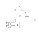
- FIG. 3 is a system configuration view showing a radio communication system including the base station of the present invention.
- a base station 100 performs radio communications between terminals A and B simultaneously, and receives signals of a reverse link transmitted from terminals A and B, and transmits signals of a forward link to the respective terminals A and B from one antenna selected among antennas 101 to 104.
- FIG. 4 is a block diagram showing the configuration of the base station according to the first embodiment of the present invention.
- transmission/reception switches 105 to 108 which are provided to use the same antenna at the receiving and transmitting time, output signals radio received by antennas 101 to 104 sheared between reception and transmission to received signal strength detectors 109 and 110. Then, transmission/reception switches 105 to 108 output transmitting signals sent from a transmission antenna change device 114 to antennas 101 to 104, respectively.
- the received signal strength detectors 109 and 110 detect received signal strength of signals received by antennas 101 to 104 and antenna numbers and their received signal strength are temporarily stored.
- the transmission antenna selector 111 selects antennas for transmitting signals to the respective terminals to be different from each other based on the received signal strength detected by the detectors 109 and 110. Then, the transmission antenna selector 111 outputs a control signal based on the selection result, and controls the transmission antenna change device 114.
- Transmitters 112 and 113 use individual carriers, respectively, and output transmitting signals with respect to different terminals to the transmission antenna change device 114.
- the transmission antenna change device 114 changes an internal switch based on the control signal output from the transmission antenna selector 111, and outputs the transmitting signals output from transmitters 112 and 113 to any one of transmission/reception switches 105 to 108.
- signals radio transmitted from the respective terminals are received by antennas 101 to 104 at the reception timing.
- the received signals are input to received signal strength detectors 109 and 110 through transmission/reception switches 105 to 108.
- a transmission antenna selector 111 selects transmission antennas from which transmitting signals with respect to the respective terminals are transmitted not be to overlapped with other based on the antenna numbers and received signal strength by transmission antenna select processing to be describe later. Then, a corresponding control signal is output to the transmission antenna change device 114, and the internal switch of the transmission antenna change device 114 is changed on the basis of the control signal.
- transmitting signals with respect to each terminal are output from transmitters 112 and 113, and radio transmitted from any one of antennas 101 to 104 through transmission antenna change device 114 and transmission/reception switches 105 to 108.
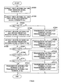
- transmission antenna select processing which is carried out by the transmission antenna selector 111 of the base station according to the first embodiment, with reference to the flowchart of FIG. 5.
- the transmitter 112 transmits data to terminal A
- transmitter 113 transmits data to terminal B
- received signal strength detectors 109 detects the received signal strength from terminal A for each antenna
- received signal strength detectors 110 detects the received signal strength from terminal B for each antenna.
- step (hereinafter referred to as "ST") 201 antenna (hereinafter referred to as “first antenna”) Xa1 of terminal A having a maximum received signal strength and the received signal strength (hereinafter referred to as “first received signal strength”) Va1 are extracted from the output of received signal strength detector 109.
- first antenna Xb2 of terminal B and first received signal strength Vb1 are extracted from the output of received signal strength detector 110.
- first antenna Xa1 of terminal A is the same as first antenna Xb1 of terminal B. Then, when first antenna Xa1 of terminal A and first antenna Xb1 of terminal B are different from each other, antenna Xa1 is selected as a transmission antenna (hereinafter referred to "transmission antenna for terminal A") of signals to be transmitted to terminal A from transmitter 112. Also, antenna Xb1 is selected as a transmission antenna (hereinafter referred to "transmission antenna for terminal B”) of signals to be transmitted to terminal B from transmitter 113 in ST204.
- antenna Xa2 (hereinafter referred to as “second antenna") having the second largest received signal strength of terminal A and the received signal strength (hereinafter referred to as “second received signal strength) Va2 are extracted in ST205. Also, second antenna Xb2 of terminal B and second received signal strength Vb2 are extracted in ST206.
- FIG. 6 is a view showing a result of transmission antenna select processing conducted by transmission antenna selector 111 of the base station according to the first embodiment.
- antennas 101 to 104 have 47dB, 40dB, 42dB, 37dB, respectively. Also, regarding the received signal strength of antennas of terminal B, antennas 101 to 104 have 50dB, 45dB, 38dB, 41dB, respectively.
- both the first antenna of terminal A and that of terminal B are antennas 101. Therefore, the transmission antenna selector 111 compares the received signal strength of the second antenna of terminal A with that of the terminal B.
- the transmission antenna selector 111 selects antenna 101 as a transmission antenna for terminal A, and antenna 102 as a transmission antenna for terminal B.
- the antennas can be thus allocated to be different from each other as the transmission antenna for each terminal. As a result, the need for providing the mixers can be eliminated, and the transmission amplifier can be downsized.
- the antenna with the maximum received signal strength is the same in two terminals, the second largest received signal strength of the antenna of one terminal is compared with that of the other terminal. Then, the antenna with a larger received signal strength is selected as a transmission antenna for the corresponding terminal, and the antenna having the maximum received signal strength is selected as a transmission antenna for the other terminal. This makes it possible to maximize an average value of the received signal strength.
- a predetermined one transmission antenna for a control channel was fixed unlike a communication channel, which carried out selective diversity based on the received signal strength.
- control channel signals are transmitted to the plurality of terminals, which perform communications with the self-station, and it is unnecessary to perform transmission diversity with respect to a specific destination station. For this reason, even if control channel signals are transmitted from any antenna, there is no difference in the quality of transmission.
- the transmission antenna for control channel is varied and the transmission antenna for communication channel is selected. Thereafter, the transmission antenna for communication channel is selected from the residual antennas, so that the performance of transmission diversity can be effectively realized.
- FIG. 7 is a block diagram showing the configuration of the base station according to the second embodiment.
- the same reference numerals as those of FIG. 4 are added to the configuration portions common to the base station of FIG. 4, and the explanation will be omitted.
- a transmission antenna selector 301 selects antennas for transmitting signals to the respective terminals to be different from each other by the process shown in FIG.4 based on the received signal strength detected by the detectors 109 and 110. Then, transmission antenna selector 301 selects an antenna for transmitting signals for control channel from the residual antennas. After that, transmission antenna selector 301 outputs a control signal based on the result of the select processing, and controls a transmission antenna change device 302.
- the transmission antenna change device 302 changes an internal switch based on the control signal output from the transmission antenna selector 111, and outputs transmitting signals sent from transmitters 112, 113, and 303 to any one of transmission/reception switches 105 to 108.
- FIG. 8 is a view showing a result of transmission antenna select processing, which is carried out by the transmission antenna selector 301 of the base station according to the second embodiment.
- antennas 101 to 104 have 37dB, 40dB, 42dB, 47dB, respectively. Also, regarding the received signal strength of antennas of terminal B, antennas 101 to 104 have 38dB, 41dB, 45dB, 50dB, respectively.
- both the first antenna of terminal A and that of terminal B are antennas 104. Therefore, the transmission antenna selector 301 compares the received signal strength of the second antenna of terminal A with that of the terminal B.
- the transmission antenna selector 301 selects antenna 104 as a transmission antenna for terminal A and antenna 103 as a transmission antenna for terminal B.
- the antenna selector 301 selects either residual antenna 101 or 102 as a transmission antenna for control channel.
- the transmission antenna for control channel is selected from the residual antennas, so that the different antennas can be allocated as the transmission antenna including one for control channel.
- the need for providing the mixers can be eliminated, the transmission amplifier can be downsized, and effective transmission diversity can be carried out.
- the third embodiment is a form in which a channel allocation is performed when communications is carried out at the same time using a plurality of frequency channels.
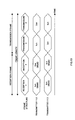
- FIGS. 9 and 10 are views each explaining a channel allocation according to the third embodiment.
- TDMA-TDD system is used as a signal division system, and four channels including channel 1 to channel 4 exist in one frame. Then, transmitter 112 performs transmission using channels 1 and 2, and transmitter 113 performs transmission using channels 3 and 4 having frequencies different from those of channels 1 and 2. Also, transmission using channels 1 and 3 is carried out at the same time, and transmission using channels 2 and 4 is carried out at the same time.
- transmitter 112 performs transmission to terminal A with about 80 dB of an average value of received signal strength by use of channel 1, and that transmission to terminal C with about 40 dB of an average value of received signal strength by use of channel 2. Then, it is assumed that a communication request with about 80 dB of the average value of received signal strength is sent from terminal B and that a communication request with about 40 dB of an average value of received signal strength is set from terminal D.
- FIG. 9 shows a case in which channel 3 is allocated to terminal B and channel 4 is allocated to terminal D.
- FIG. 10 shows a case in which channel 3 is allocated to terminal D and channel 4 is allocated to terminal B.
- the difference in the average value of received signal strength is decreased (about 0 dB). Also, when the channel allocation is made as shown in FIG. 10, the difference in the average value of received signal strength is increased (about 40 dB).
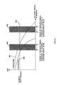
- FIG. 11 is a view showing the relationship between received signal strength and BER (Bit Error Rate) when the channel allocation is made as shown in FIG. 10.
- a shaded area 401 denotes the range of received signal strength of channel 1
- a shaded area 402 denotes the range of received signal strength of channel 3.
- a dotted line 403 denotes a boundary whether or not a desired performance of transmission diversity is satisfied.
- a solid line 404 denotes a BER characteristic curve when three branch diversity transmission in which one antenna is selected from three antennas is performed.
- a solid line 405 denotes a BER characteristic curve when four branch diversity transmission in which one antenna is selected from four antennas is performed.
- solid line 405 falls below dotted line 403 but solid line 404 does not fall below solid line 403 in the range of received signal strength of channel 1, which is about 40 dB of the average value of received signal strength. Namely, it is apparent that the desired performance can be satisfied when four branch diversity transmission is performed but it cannot be satisfied when three branch diversity transmission is performed.
- both solid lines 405 and 404 fall below dotted line 403 in the range of received signal strength of channel 3, which is about 80 dB of the average value of received signal strength. Then, it is apparent that the desired performance can be satisfied when four branch diversity transmission or three branch diversity transmission is performed.
- the channel allocation is performed to increase the difference in the average value of received signal strength and transmission antenna select processing as explained in the first or second embodiment is performed.
- second received signal strength of the channel with a low average value of received signal strength is made smaller than second received signal strength of the channel having a high average value of received signal strength.
- the antenna selection is always performed with respect to the channel having a low average value of received signal strength by priority over all.
- four branch diversity transmission operation is performed with respect to the channel having a low average value of received signal strength
- four branch diversity transmission operation or three branch diversity transmission operation is performed with respect to the channel having a high average value of received signal strength. This satisfies the desired performance without fail.
- each channel is allocated to increase the difference in the average value of received signal strength. This makes it possible to realize transmission diversity, which satisfies the desired performance.
- the above embodiments were explained using the base station as an example of a radio communication apparatus.
- the present invention is not limited to the base station, and the same effect can be obtained in the other radio communication apparatuses.
- the different antenna can be allocated as the transmission antenna for each terminal.
- the need for providing the mixers can be eliminated, and a maximum output of a transmission amplifier can be reduced without deteriorating quality of transmitting signals.
Landscapes
- Engineering & Computer Science (AREA)
- Computer Networks & Wireless Communication (AREA)
- Signal Processing (AREA)
- Radio Transmission System (AREA)
- Transmitters (AREA)
Applications Claiming Priority (2)
| Application Number | Priority Date | Filing Date | Title |
|---|---|---|---|
| JP10308915A JP2000138624A (ja) | 1998-10-29 | 1998-10-29 | 無線通信装置及び送信アンテナ切替方法 |
| JP30891598 | 1998-10-29 |
Publications (2)
| Publication Number | Publication Date |
|---|---|
| EP0998056A2 true EP0998056A2 (de) | 2000-05-03 |
| EP0998056A3 EP0998056A3 (de) | 2006-04-05 |
Family
ID=17986814
Family Applications (1)
| Application Number | Title | Priority Date | Filing Date |
|---|---|---|---|
| EP99121157A Withdrawn EP0998056A3 (de) | 1998-10-29 | 1999-10-22 | Funkübertragungsvorrichtung und Verfahren zum Umschalten der Sendeantenne |
Country Status (4)
| Country | Link |
|---|---|
| US (1) | US6281840B1 (de) |
| EP (1) | EP0998056A3 (de) |
| JP (1) | JP2000138624A (de) |
| CN (1) | CN1125540C (de) |
Cited By (4)
| Publication number | Priority date | Publication date | Assignee | Title |
|---|---|---|---|---|
| EP1316193A1 (de) * | 2000-08-03 | 2003-06-04 | Morphics Technology, Inc. | Dynamisches rekonfigurierbares universelles sendersystem |
| EP1507340A1 (de) * | 2002-05-23 | 2005-02-16 | NEC Corporation | Adaptive antennensende-/-empfangsvorrichtung |
| WO2007034037A1 (en) * | 2005-09-19 | 2007-03-29 | Nokia Corporation | Operating multi-service receiver in non-interfering manner |
| GB2507131A (en) * | 2012-10-19 | 2014-04-23 | Broadcom Corp | Switching transmitter antenna based on evaluation of received signals |
Families Citing this family (27)
| Publication number | Priority date | Publication date | Assignee | Title |
|---|---|---|---|---|
| JP2001128215A (ja) * | 1999-10-29 | 2001-05-11 | Matsushita Electric Ind Co Ltd | Tdma−tdd方式送受信装置および送受信方法 |
| US6654384B1 (en) * | 1999-12-30 | 2003-11-25 | Aperto Networks, Inc. | Integrated self-optimizing multi-parameter and multi-variable point to multipoint communication system |
| US6459895B1 (en) * | 2000-09-26 | 2002-10-01 | Neoreach, Inc. | Methods for making a cellular system, transmitting to a mobile user in a cellular system, and evaluating the performance of a cellular system |
| US6636488B1 (en) | 2000-10-11 | 2003-10-21 | Aperto Networks, Inc. | Automatic retransmission and error recovery for packet oriented point-to-multipoint communication |
| US6947748B2 (en) | 2000-12-15 | 2005-09-20 | Adaptix, Inc. | OFDMA with adaptive subcarrier-cluster configuration and selective loading |
| WO2004013988A1 (fr) * | 2002-08-05 | 2004-02-12 | Huawei Technologies Co., Ltd | Procedes de selection d'antennes d'emission dans un environnement de communication a antennes multiples et procedes d'emission et de reception du signal |
| CN100392994C (zh) * | 2002-11-08 | 2008-06-04 | 中兴通讯股份有限公司 | 一种无线通信系统天线转换分集的方法 |
| GB0316402D0 (en) * | 2003-07-12 | 2003-08-13 | Qinetiq Ltd | Direction finding |
| JP2005110228A (ja) * | 2003-09-10 | 2005-04-21 | Matsushita Electric Ind Co Ltd | セキュア通信方法および送信装置、受信装置 |
| US7142107B2 (en) | 2004-05-27 | 2006-11-28 | Lawrence Kates | Wireless sensor unit |
| US7933628B2 (en) * | 2004-08-18 | 2011-04-26 | Ruckus Wireless, Inc. | Transmission and reception parameter control |
| US7573851B2 (en) | 2004-12-07 | 2009-08-11 | Adaptix, Inc. | Method and system for switching antenna and channel assignments in broadband wireless networks |
| US7515940B2 (en) * | 2005-03-22 | 2009-04-07 | Cisco Technology, Inc. | Node dependent wireless transmit antenna selection technique |
| WO2007005947A1 (en) | 2005-07-01 | 2007-01-11 | Terahop Networks, Inc. | Nondeterministic and deterministic network routing |
| JP2007104054A (ja) * | 2005-09-30 | 2007-04-19 | Oki Electric Ind Co Ltd | データ通信装置、データ通信方法及びデータ通信プログラム |
| KR100811238B1 (ko) | 2006-08-03 | 2008-03-07 | 유우영 | 지하철의 플랫폼 상태를 모니터링하기 위한 데이터 송수신 시스템 |
| WO2009151877A2 (en) | 2008-05-16 | 2009-12-17 | Terahop Networks, Inc. | Systems and apparatus for securing a container |
| JP4935794B2 (ja) * | 2008-10-17 | 2012-05-23 | 富士通株式会社 | 無線通信装置及び無線通信方法 |
| TWI435563B (zh) * | 2009-01-07 | 2014-04-21 | Realtek Semiconductor Corp | 無線網路中傳輸路徑選擇裝置與方法 |
| CN101710839B (zh) * | 2009-08-07 | 2014-04-02 | 无锡德通数据无线通信科技有限公司 | 无线ofdm/tdd系统的多天线选择性发送分集方法 |
| CN102487284B (zh) * | 2010-12-02 | 2014-03-26 | 四零四科技股份有限公司 | 具非对称增益天线的通讯装置及其通讯方法 |
| TWI454071B (zh) * | 2012-01-05 | 2014-09-21 | Realtek Semiconductor Corp | 支援天線分集機制的無線通信電路 |
| US9893715B2 (en) * | 2013-12-09 | 2018-02-13 | Shure Acquisition Holdings, Inc. | Adaptive self-tunable antenna system and method |
| CN107733512A (zh) * | 2016-08-10 | 2018-02-23 | 华硕电脑股份有限公司 | 传输装置、无线网络传输系统与其方法 |
| CN108233958A (zh) * | 2017-12-27 | 2018-06-29 | 哈尔滨工业大学(威海) | 一种通信方法、通信装置、通信设备及浮标 |
| CN110830071A (zh) * | 2019-11-12 | 2020-02-21 | 天津津航计算技术研究所 | 一种多天线射频前端电路 |
| CN112910535B (zh) * | 2021-02-05 | 2023-03-24 | 陕西天基通信科技有限责任公司 | 一种提高5g直放站覆盖效率的方法 |
Citations (2)
| Publication number | Priority date | Publication date | Assignee | Title |
|---|---|---|---|---|
| WO1998024195A1 (fr) * | 1996-11-26 | 1998-06-04 | Sanyo Electric Co., Ltd. | Station de base pour systeme de communication mobile |
| GB2323750A (en) * | 1997-01-23 | 1998-09-30 | Nec Corp | TDMA transmission diversity circuit |
Family Cites Families (1)
| Publication number | Priority date | Publication date | Assignee | Title |
|---|---|---|---|---|
| US5701596A (en) * | 1994-12-01 | 1997-12-23 | Radio Frequency Systems, Inc. | Modular interconnect matrix for matrix connection of a plurality of antennas with a plurality of radio channel units |
-
1998
- 1998-10-29 JP JP10308915A patent/JP2000138624A/ja active Pending
-
1999
- 1999-10-22 EP EP99121157A patent/EP0998056A3/de not_active Withdrawn
- 1999-10-25 US US09/426,199 patent/US6281840B1/en not_active Expired - Fee Related
- 1999-10-29 CN CN99125444A patent/CN1125540C/zh not_active Expired - Fee Related
Patent Citations (2)
| Publication number | Priority date | Publication date | Assignee | Title |
|---|---|---|---|---|
| WO1998024195A1 (fr) * | 1996-11-26 | 1998-06-04 | Sanyo Electric Co., Ltd. | Station de base pour systeme de communication mobile |
| GB2323750A (en) * | 1997-01-23 | 1998-09-30 | Nec Corp | TDMA transmission diversity circuit |
Cited By (15)
| Publication number | Priority date | Publication date | Assignee | Title |
|---|---|---|---|---|
| US7233810B2 (en) | 2000-08-03 | 2007-06-19 | Infineon Technologies Ag | Dynamically reconfigurable universal transmitter system |
| US8515352B2 (en) | 2000-08-03 | 2013-08-20 | Intel Mobile Communications GmbH | Dynamically reconfigurable universal transmitter system |
| EP1316193A4 (de) * | 2000-08-03 | 2005-12-28 | Infineon Technologies Ag | Dynamisches rekonfigurierbares universelles sendersystem |
| US7039915B2 (en) | 2000-08-03 | 2006-05-02 | Infineon Technologies Ag | Method and apparatus for software-based allocation and scheduling of hardware resources in an electronic device |
| EP1746850A3 (de) * | 2000-08-03 | 2007-03-21 | Infineon Tehnologies AG | Dynamisch, rekonfigurierbares, universelles Sendersystem |
| US8781399B2 (en) | 2000-08-03 | 2014-07-15 | Intel Mobile Communications GmbH | Dynamically reconfigurable universal transmitter system |
| EP1316193A1 (de) * | 2000-08-03 | 2003-06-04 | Morphics Technology, Inc. | Dynamisches rekonfigurierbares universelles sendersystem |
| EP1507340A4 (de) * | 2002-05-23 | 2010-12-29 | Nec Corp | Adaptive antennensende-/-empfangsvorrichtung |
| EP1507340A1 (de) * | 2002-05-23 | 2005-02-16 | NEC Corporation | Adaptive antennensende-/-empfangsvorrichtung |
| WO2007034037A1 (en) * | 2005-09-19 | 2007-03-29 | Nokia Corporation | Operating multi-service receiver in non-interfering manner |
| US9160464B2 (en) | 2005-09-19 | 2015-10-13 | Nokia Technologies Oy | Operating multi-service receiver in non-interfering manner |
| GB2507131A (en) * | 2012-10-19 | 2014-04-23 | Broadcom Corp | Switching transmitter antenna based on evaluation of received signals |
| GB2507131B (en) * | 2012-10-19 | 2015-06-10 | Broadcom Corp | Methods, devices, and computer program products improving mobile communication |
| US9294182B2 (en) | 2012-10-19 | 2016-03-22 | Broadcom Corporation | Methods, devices, and computer program products improving mobile communication |
| US9544011B2 (en) | 2012-10-19 | 2017-01-10 | Broadcom Corporation | Methods, devices, and computer program products improving mobile communication |
Also Published As
| Publication number | Publication date |
|---|---|
| CN1125540C (zh) | 2003-10-22 |
| CN1258138A (zh) | 2000-06-28 |
| EP0998056A3 (de) | 2006-04-05 |
| JP2000138624A (ja) | 2000-05-16 |
| US6281840B1 (en) | 2001-08-28 |
Similar Documents
| Publication | Publication Date | Title |
|---|---|---|
| EP0998056A2 (de) | Funkübertragungsvorrichtung und Verfahren zum Umschalten der Sendeantenne | |
| US7203165B1 (en) | Data transmission device and method | |
| JP3078216B2 (ja) | 基地局選択方法 | |
| KR100289794B1 (ko) | 디지털 이동무선 통신시스템에서 업링크 매크로 다이버시티 방법 및 장치 | |
| EP0891048B1 (de) | Empfangsdaten Basisfunkstationsübertragungssystem für Site-Diversity in der Aufwärtsrichtung in einem Mobilkomminikationssytem | |
| US6198928B1 (en) | Handover method, and a cellular radio system | |
| EP2175572B1 (de) | Gerät und Verfahren zum Übertragen und Empfangen | |
| EP0889603A2 (de) | Sende-Diversityanordnung | |
| US5161252A (en) | Diversity antenna communication system | |
| US20040110524A1 (en) | Mobile communication control method, cellular system, mobile station, base station, and base station control apparatus | |
| US5678183A (en) | Mobile transmitter which does not cause a disruption of communication when moving between communication systems with different modulation schemes | |
| WO1997008909A1 (en) | A method of levelling a traffic load of a base station in a cellular radio system, and a cellular radio system | |
| US6396821B1 (en) | Radio communication apparatus of diversity transmission system | |
| HU218533B (hu) | Kommunikációs eljárás és rendszer, továbbá mobil és bázis rádióállomás | |
| IE66394B1 (en) | A relay base for a radiotelephone communication system | |
| EP1137302A1 (de) | Kommunikationsendgerät und verfahren zur wahl der übertragunsstations | |
| CN1083181C (zh) | 跳接传送数字分组数据信号的方法和装置 | |
| US8041326B2 (en) | Data transmission method | |
| JP3402426B2 (ja) | ダイバーシチ送信装置および方法 | |
| EP0833465B1 (de) | Verfahren und System zur drahtlosen Übertragung mit Sender-Empfänger und mehreren drahtlosen Endgeräten | |
| JPH0613947A (ja) | マルチパス通信用無線装置 | |
| JP2002300072A (ja) | Hf無線回線用送受信装置 | |
| KR100405159B1 (ko) | 통신 시스템에서 통신 자원의 신호 품질을 판정하기 위한 통신 장치와 방법 | |
| JP2581424B2 (ja) | ホットスタンバイ送受信装置 | |
| JPH03135233A (ja) | 移動通信用一周波数交互通信方式 |
Legal Events
| Date | Code | Title | Description |
|---|---|---|---|
| PUAI | Public reference made under article 153(3) epc to a published international application that has entered the european phase |
Free format text: ORIGINAL CODE: 0009012 |
|
| AK | Designated contracting states |
Kind code of ref document: A2 Designated state(s): AT BE CH CY DE DK ES FI FR GB GR IE IT LI LU MC NL PT SE |
|
| AX | Request for extension of the european patent |
Free format text: AL;LT;LV;MK;RO;SI |
|
| PUAL | Search report despatched |
Free format text: ORIGINAL CODE: 0009013 |
|
| AK | Designated contracting states |
Kind code of ref document: A3 Designated state(s): AT BE CH CY DE DK ES FI FR GB GR IE IT LI LU MC NL PT SE |
|
| AX | Request for extension of the european patent |
Extension state: AL LT LV MK RO SI |
|
| AKX | Designation fees paid | ||
| STAA | Information on the status of an ep patent application or granted ep patent |
Free format text: STATUS: THE APPLICATION IS DEEMED TO BE WITHDRAWN |
|
| 18D | Application deemed to be withdrawn |
Effective date: 20061227 |
|
| REG | Reference to a national code |
Ref country code: DE Ref legal event code: 8566 |