EP0997308B1 - Druckgerät und Verfahren zur Erzeugung eines gleichmässigen Druckes zum Niederhalten von Druckmedien - Google Patents
Druckgerät und Verfahren zur Erzeugung eines gleichmässigen Druckes zum Niederhalten von Druckmedien Download PDFInfo
- Publication number
- EP0997308B1 EP0997308B1 EP19990102977 EP99102977A EP0997308B1 EP 0997308 B1 EP0997308 B1 EP 0997308B1 EP 19990102977 EP19990102977 EP 19990102977 EP 99102977 A EP99102977 A EP 99102977A EP 0997308 B1 EP0997308 B1 EP 0997308B1
- Authority
- EP
- European Patent Office
- Prior art keywords
- medium
- vacuum
- platen
- chambers
- vacuum source
- Prior art date
- Legal status (The legal status is an assumption and is not a legal conclusion. Google has not performed a legal analysis and makes no representation as to the accuracy of the status listed.)
- Expired - Lifetime
Links
Images


Classifications
-
- B—PERFORMING OPERATIONS; TRANSPORTING
- B41—PRINTING; LINING MACHINES; TYPEWRITERS; STAMPS
- B41J—TYPEWRITERS; SELECTIVE PRINTING MECHANISMS, i.e. MECHANISMS PRINTING OTHERWISE THAN FROM A FORME; CORRECTION OF TYPOGRAPHICAL ERRORS
- B41J11/00—Devices or arrangements of selective printing mechanisms, e.g. ink-jet printers or thermal printers, for supporting or handling copy material in sheet or web form
- B41J11/0085—Using suction for maintaining printing material flat
-
- B—PERFORMING OPERATIONS; TRANSPORTING
- B41—PRINTING; LINING MACHINES; TYPEWRITERS; STAMPS
- B41J—TYPEWRITERS; SELECTIVE PRINTING MECHANISMS, i.e. MECHANISMS PRINTING OTHERWISE THAN FROM A FORME; CORRECTION OF TYPOGRAPHICAL ERRORS
- B41J13/00—Devices or arrangements of selective printing mechanisms, e.g. ink-jet printers or thermal printers, specially adapted for supporting or handling copy material in short lengths, e.g. sheets
- B41J13/10—Sheet holders, retainers, movable guides, or stationary guides
- B41J13/22—Clamps or grippers
- B41J13/223—Clamps or grippers on rotatable drums
- B41J13/226—Clamps or grippers on rotatable drums using suction
Definitions
- the present invention generally relates to hardcopy apparatus, such as copiers, printers, scanners, facsimiles, and more particularly to improved media holddown devices for such apparatus.
- paper flatness is maintained by establishing electrostatic attraction between a flat support plate on the printer and the back surface of a sheet to be printed.
- sheet flatness is maintained by providing suction between a support plate and the back surface of a sheet to be printed. It should be noted that, in either type of holddown device, direct contact of the holddown device with the printed surface is avoided to minimise ink smearing and other adverse affects on print appearance.
- a printer having a platen 60'' wide may be used to handle not only media of the same nominal size, i.e. 60'', but also smaller width such as: 50'', 42'', 24'' or down to 8.5''.
- This printer employs a single vacuum chamber connected to a fan having at the end, further from the fan, a wall which is slidable in a horizontal direction to increase or reduce the dimension of the vacuum chamber itself.
- a pinch roller is mounted on this wall, to engage a border of the medium.
- the opposite border of the media is engaged by a second fixed pinch roller, located at one end of the print zone.
- US5414491 and US3584954 disclose hardcopy apparatuses according to the preamble of claim 1 comprising a valve or a mechanical actuator for selectively communicating the vacuum chambers with the vacuum source.
- the present invention seek to provide an improved hardcopy apparatus and method of holding down a medium in the hardcopy apparatus.
- the present invention can be particularly suitable to inkjet printers which preferably require a media to be periodically accurately indexed across a print zone defined in the printer for receiving the ink.
- the pressure generated in at least one of the two chambers is independent from the pressure generated in the remaining chamber or chambers. More preferably, the pressure generated in a number of the at least two chambers is substantially not affecting the uniformity of the pressure in another chamber of the at least two chambers.
- a bypass conduit is employed to interface one of the at least two chambers to the vacuum source by passing the remaining chamber or chambers. Moreover, each but one of the at least two chambers is interfaced to the vacuum source by a substantially independent bypass conduit.
- At least one of the at least two chambers is connected to the vacuum source via an aperture, substantially reducing the air circulation toward the vacuum source.
- the reduction of air circulation in the chamber helps the vacuum source to generate higher depression in the vacuum chambers.
- the vacuum source comprises at least a fan and more preferably at least two fans in series, for maintaining a smaller diameter of the fan but increasing the total power of the vacuum source.
- substantially the same pressure is applied to each different portion of the medium.
- said negative pressure is substantially uniformly applied to the back of the medium.
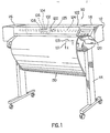
- a printer 110 includes a housing 112 mounted on a stand 114.
- the housing has left and right drive mechanism enclosures 116 and 118.
- a control panel 120 is mounted on the right enclosure 118.
- a carriage assembly 100 illustrated in phantom under a cover 122, is adapted for reciprocal motion along a carriage bar 124, also shown in phantom.
- the carriage assembly 100 comprises four inkjet printheads 102, 104, 106, 108 that store ink of different colours, e.g. black, magenta, cyan and yellow ink respectively, and an optical sensor 105.
- the position of the carriage assembly 100 in a horizontal or carriage scan axis (Y) is determined by a carriage positioning mechanism with respect to an encoder strip. (not shown).
- a print medium 130 such as paper is positioned along a vertical or media axis by a media axis mechanism (not shown).
- the media axis is called the X axis denoted as 101
- the scan axis is called the Y axis denoted as 103.
- an holddown system is globally referenced as 200.
- Such a holddown system 200 is located between the left and right drive mechanism enclosures 116 and 118.
- the width of the holddown system along the Y axis is at least equal to the maximum allowable width of the media. In this example it should allow the employment of medium having width up to 36'', i.e. 914 mm. In a different embodiment the hold down system may allow the employment of medium having width up to 60 inches or more.
- the inkjet printheads 102, 104, 106, 108, are held rigidly in the movable carriage 100 so that the printhead nozzles are above the surface of a portion of the medium 130 which lays substantially flat on a flat stationary support platen 400 of said holddown system 200.
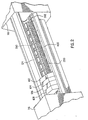
- the flat platen 400 is shown in more details, and is located in a front position of the printer 110 and co-operate with a main driving roller 300, in the following identified also as the main roller, located in a rear position, and a plurality of pinch wheels 310, in this example 12 pinch wheels 310 are employed, which are controlled to periodically index or convey the medium across the surface of the platen 400.
- the force between each pinch wheels 310 and the main roller 300 is comprised between 3.33 N and 5 N, preferably 4.15 N.
- the main roller 300 is provided with a conventional surface having a plurality of circumferencial recesses 305 housing a corresponding plurality of protrusions 405 of the platen 400 extending towards the rear of the printer 110.
- This combination of features allows the medium 130 to reliably move from the main roller 300 to the platen 400 and vice versa.
- the gap between the roller 300 and the platen 400 may allow an edge of the medium to engage the back of the platen itself causing a paper jam.
- the printer 110 comprises, a vacuum source, in this case a fan 700 shown in Figure 7 , connected to the atmosphere through a plurality of holes, or apertures, 330, 350 and a vacuum chamber globally referred as 380; such vacuum source generates an air flow by sucking air from the atmosphere.
- a vacuum source in this case a fan 700 shown in Figure 7
- 380 a vacuum chamber globally referred as 380; such vacuum source generates an air flow by sucking air from the atmosphere.
- a connecting conduit 650 is connecting the fan 700 to the vacuum channel 380 which extends below the platen 400 along all the print zone of the printer.
- Such vacuum channel 380 comprises a plurality of vacuum chambers, each one has been designed as to maintain a certain negative pressure, or allowing a certain air circulation, in the chamber without substantially affecting any air flow or negative pressure which may be present in other chambers.
- vacuum channel 380 comprises 2 chambers 382, 383, which are both connected by a unique close conduit 650 to the same fan 700.
- the first chamber 382 is straightly laying directly below a first region of the platen which in this example is wide 24'' in the scan axis direction.
- the second chamber 383 lays next, but separated by a wall 385, to the first chamber 382 and extend it to the end of the platen.
- the second chamber 383 is straightly laying directly below a second region of the platen, which is, in this example 12'' wide in the scan axis direction.
- a bypass conduit 381 extends below the first chamber 382 and the second chamber 383 for all the width of the platen 400, putting in communication the second chamber 383 with the connecting conduit 650.
- the second chamber 383, 12'' wide, and the first chamber, 24'' wide provide the 36'' platen 400 with vacuum along its complete extension.
- the holes 330, 350 are distributed at a certain distance from the main roller.
- a plurality of first holes 330 lays in a line at a distance comprised between 10 mm and 30 mm, preferably 19 mm and a plurality of secondary holes 350, distributed preferably in line.
- the platen 400 is provided, according to this preferred example, with a plurality of substantially linear grooves having one end closer to and the opposed end further from the main roller 300. Such grooves are linked together to form a continuos slot 320, which crosses substantially the whole width of the platen 400, where such a continuous slot 320 is arranged to have a waved shape.
- the plurality of first holes, or slot holes 330, having a diameter comprises between 1.5 mm and 3.5 mm, preferably about 2.5 mm, are then distributed inside the waved slot 320, and in this embodiment are preferably located in the further part of the slot 320 with respect to the main roller 300.
- the size of the vacuum channel is a further parameter relevant to apply the proper vacuum to the back of the medium.
- the surface of the sum of the squared sections of the vacuum chambers 382, 383, as depicted in Figure 3 is preferably bigger than the sum of the surface of all the apertures 330, 350 distributed within the platen 400. More preferably the sum of the sections of the chambers 382, 383 is as big as twice, or more, the sum of the surface of all the apertures 330, 340.
- the squared section of the bypass conduit 381 is providing a better approximation, since is this dimension which is actually influencing the air flow speed or the amount of negative pressure available in the second chamber.
- the section of the bypass conduit 381 is smaller than the section of the first chamber 282 since the first chamber 382 is connected to atmosphere through a first group of holes (first and secondary holes 330, 350) distributed on 24" of platen, while the bypass conduit 381 is connected to the atmosphere through the second chamber 383 and a second group of holes (first and secondary holes 330, 350) distributed on the remaining 12'' of platen.
- FIG. 7 the behaviour of the vacuum unit is shown.
- the fan 700 When the fan 700 is operating and no media is placed on the platen 400, air is sucked through the various holes 300, 350 placed on the platen 400 and two substantially independent air flows are generated.
- a first air flow 710 is guided within the first vacuum chamber 382 while a second air flow 720 is guided within the second vacuum chamber 383 and the vacuum bypass 381, both towards the fan 700.
- the two air flows 710, 720 are mixed together at the entrance into the connecting conduit 650 and finally end in the fan, which expulses the sucked air into the atmosphere again.
- the air flows mixes at the very end of channel 380 and this cause a small loss of pressure in the pressure generation.
- the length of the bypass 383 and the first chamber 382 compared to the length of the zone where the two air flows are mixed is very big, the non-uniformity would be hardly noticeable.
- a 24'' size medium is placed onto the platen, in correspondence of the first vacuum chamber 382 and covering all the apertures of the platen available in the first region.
- the first air flow 710 becomes of negligible intensity and the action of the fan is converted into a uniform negative pressure applied to the back of the medium.
- the second air flow 720 is still free to circulate in the vacuum channel 380, but only through the second chamber 383, the bypass 381, without substantially affecting the uniformity of the pressure provided in the first chamber 382.
- a 36" size medium is placed onto the platen, in correspondence of both the vacuum chambers and closing all the apertures available in the first and the second regions of the platen 400.
- a uniform negative pressure is generated in all the vacuum channel 380, i.e. in the first and second vacuum chambers 382, 383 and in the bypass 381.
- the platen is be divided into 4 regions,, placed side by side in the scan axis direction, having sizes equal to 36'', 6", 8'' and 6'', to more precisely handle medium having sizes of 36'', 42'', 54" and 60''.
- the vacuum channel 380 comprises 4 vacuum chambers, 690, 691, 692, 693, distributed side by side, and separated each other by a wall 685, having width of 36'', 6", 8'', 6''; each region is placed in correspondence of one of the 4 regions defined on the platen 400.
- all the vacuum chambers are connected to the vacuum conduit 650, each one, but the vacuum chamber 693 closer to the vacuum source, by means of an independent bypass conduit, 680, 681, 682.
- Figure 10 shows how the different bypass conduits 680, 681, 682 may be distributed in the vacuum channel. It is know that to make a common fan to work at high-pressure levels the incoming air flow should be small. In fact fan behaviour is defined by a function that relates airflow versus pressure/depression (it depends on how the fan is working).
- each vacuum chamber is connected to its bypass conduit by means of a narrow bypass aperture 660.
- the bypass aperture is so small that the pressure losses grow very rapidly, thus making the air flow through (and so towards the fan) it very small.
- the vacuum source since there is a wider first vacuum chamber 693 and it is still required that sufficient negative pressure is applied to the back of media of small size (e.g. 8.5''), the vacuum source has an increase power.
- the vacuum source may comprises a first and a second fans, placed in series, both of the same power of the one employed in the first example. However, such fans may also placed in parallel. This allows to obtain an increased power but maintaining the same small diameter of the fan.
- the vacuum channel comprises an increased number of independent vacuum chambers of limited dimensions, connected to the atmosphere through the plurality of apertures provided on the platen 400.
- Each independent chamber is also connected to a bigger common vacuum conduit via an additional narrow aperture.
- the vacuum source is directly connected to said common vacuum conduit.
- the common vacuum conduit is capable to maintain a uniform negative pressure also when an independent chamber have pressure equal to 0 (no media is present on top of it) or to provide an independent chamber with substantially its same pressure when its corresponding platen apertures are closed by media.
- the vacuum can be only directly generated at a certain distance from the main roller 300 itself.
- the vacuum source when the vacuum source is activated and in presence of a medium on the platen 400, the vacuum can be expanded along all the slot extending the vacuum closer to the main roller 300.
- extending the vacuum means that the vacuum generated at one aperture, which is normally supplied to an area of the back of medium, is now supplied to an area of the back of the medium which is at least 10% bigger, preferably bigger than 500%.
- the medium can still be indexed by the main roller 300 and the pinch rollers 310 even when we are printing close to the very end of the medium itself.
- high vacuum may crease the paper especially if the grooves of the slot 320 are wide and run parallel to the paper advance direction. Therefore is advisable to run the grooves at about 45° respect to the media axis X and optimise the slot width to minimise creases in the paper and to evenly distribute the vacuum.
- the groove if the groove is parallel to the advance direction, it may make the ink to migrate and create localised dark areas.
- the slot 320 has a depth deeper than 0.5 mm, preferably 1 mm, and a width comprises between 3 mm and 8 mm, preferably 5 mm.
- the continuous shape of the waved slot 320 helps the holddown system 200 to evenly distribute the vacuum along the print zone 450.
- an interrupted sequence of grooves may create areas, having a reduced vacuum, which cross the complete print zone 450, in the media axis direction X. This may force the ink applied in those areas to migrate and create localised dark or clear portions in the printout.
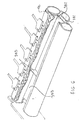
- each recess 360 is composed by two parts, a first one substantially squared and a second one substantially triangular, where the triangular part lays on a plane which deeper than the plane on which the squared part lays.
- each squared part is provided with a secondary hole 350, having a diameter comprises between 1.5 and 2.5 mm, preferably 2.0.
- Such sequence of secondary recesses 360 is combined with a sequence of overdrive wheels 340, forming a secondary roller 345, such that a group of 3 consecutive secondary recesses 360 is disposed between two consecutive wheels 340.
- Such a secondary roller is housed in the vacuum channel 380.
- this holddown system 200 comprises 12 overdrive wheels 340 equally separated along the scan axis (Y) to supply equal traction to each part of the medium.
- an overdrive wheel may mean a single wheel as well as a plurality of wheels in strict contact one to another, in order to build a wheel having a larger width.
- a secondary recess 360 is distanced by each adjacent element, both a further secondary recess 360 or a wheel 340, by a rib 370.
- the ribs are employed to reduce the risk of generating cockle wrinkles which may extend towards the print zone 450.
- two consecutive ribs 370 having a preferably height of 1 mm, are distanced one to another by a distance comprised between 15 mm and 25 mm, preferably about 20 mm if the two ribs 370 are separated by a secondary recess 360.
- the plurality of secondary holes 350 provides the vacuum channel 380 with further apertures for the air flow generated by the vacuum source.
- the particular shape of the recesses 360 helps to provide the air flow with a smooth transition, reducing the resulting noise.
- the vacuum generated in correspondence of the secondary holes 350 is extended, in order to apply a negative pressure to most of the medium 130 laying on the platen 400.
- the vacuum is extended particularly due to the presence of the overdrive wheels 340, and the ribs 370, which create a larger empty space between the medium 130 and the platen 400.
- this part of the holddown system helps the printer to reduce the cockle effect on the printout.
- a secondary roller 345 having the function of tensioning the paper during the printing operation, may help in controlling the occurrence of the cockle wrinkles in the printout.
- vacuum is furnished through the plurality of holes 350 and the gap between each overdrive wheel 340 and its surrounding portion of the platen 400.
- Vacuum is used to provide the force between medium and overdrive wheels 340; the design has been done in such a way that it can provide the required force to the overdrive wheel 340, preferably comprised between 0.6 N and 1 N, in this example 0.8 N per each wheel 340, without employing starwheels. Elimination of starwheels is an important issue since it helps to avoid a) the risk of damaging the printout with starwheel marks, b)the need to employ a mechanism or a structure to hold the starwheels themselves.
- the overdrive interference i.e. the distance between the surface of the platen 400 and the top of the a overdrive roller 340, is preferably maintained between 0.3 mm and 0.6 mm. Below 0.25 mm the traction falls quickly, towards zero traction at zero interference; if the interference is bigger than 0.65 mm, wrinkles created by the overdrive roller 340 can extend to the print zone 450.
- first reference sign 390 is traversing all the platen 400 from the right to the left side in the scan axis (Y) direction.
- first reference 390 is tangent to the slot 320, on the side closer to the main roller 300, and it could be in colour and/or in under-relief.
- This feature is used preferably in combination with a second reference 392, placed at one side end of the platen 400.
- the second reference is traversing the platen 400 in the media axis (X) direction, preferably starting from the first reference 390 to the end of the platen 400 further from the main roller 300.
- the user is provided with two references for placing correctly the edges of a cut media sheet, or a media roll, onto the platen 400 in order to load and feed the sheet into the printer 110.
- the first reference 390 is providing the user with a reference which can fully match an edge of the sheet, so simplifying the loading operation.
- a second reference is placed at one end of the platen 400, which is conventionally located at the right end of the printer, respect to the user placing the sheet.
- This combination of references enhances the easiness of the loading operation by the user, reducing the occurrence of inaccurate positioning of the medium, which may cause a paper jam, during the feeding or the printing phases.
- FIG. 4 it is shown the main roller 300 and one of the pinch wheels 310 co-operating with one protrusion 405 of the platen 400 holding the medium 130.
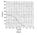
- FIG. 5 a diagram showing nominal values supplied by the vacuum source, a fan, employed in this example. Those values have been measured running the fan at its full power of 24 V.
- the pressure unit on the Y axis is Pascal and air flow unit on the X axis is m 3 /min.
- Vacuum required to eliminate cockle wrinkles in a printer would be so high that is normally unfeasible; in fact, high vacuum may suck the ink right through the paper and at the same time generate a lot of noise.
- the vacuum level has been preferably set between 380 Pa and 440 Pa, which can be achieved by a small fan, producing acceptable level of noise, i.e. about 65 dBA.
- one characteristic of the fan considered particularly valuable has been the capability of providing a pressure of 300 Pa, when the air flow is at about 0.5 m 3 /min.
- a loading operation can be activated in a plurality of different ways, e.g. by a user selection of the operation from the front panel 120 of the printer 110, or more easily, as in this embodiment, by opening the cover 122.
- the vacuum source is powered on, at 16 V, in order to help the loading operation.
- a user In order to load a cut sheet of media into the printer, a user should place the top edge of the medium 130 in correspondence of the first reference 390, and the top portion of the right edge of the same medium 130 in correspondence of the second reference. During all this phase the vacuum on is helping the user in holding the medium 130 adherent to the platen 400, so that small adjustments in the position of the medium 130 can be done using only one hand. Accordingly, the risk of inadvertently damaging the medium 130 (e.g. due to fingerprints or to the fall of the medium 130 on the ground) are minimised.
- the feeding step may be activated in several ways. For instance, it is automatically activated after that sensors have sensed the proper positioning of the medium 130, or by user selection of the feeding operation from the front panel 118, or, as in this embodiment, by closing the cover 122.
- the overdrive wheels 340 start to move clockwise in order to advance the medium 130 towards the main roller 300, until the medium 130 itself is engaged between the main roller and the pinch wheels 310.
- the vacuum is maintained on to transmit the traction force from the overdrive wheels 340 to the medium 130.
- the main roller 300 in co-operation with the pinch rollers 310 and other conventional elements of the printer 110, starts to convey the medium, from the feeding guide, across the print zone defined onto the platen 400.
- the vacuum source is switched on, at a power according to the kind of media employed and/or to the kind of plot which will be printed.
- the vacuum is keeping the medium 130 substantially flat onto the print zone 450 defined on the platen 400 to allow a quality printing.
- the main roller is advancing the medium towards the overdrive wheels 340, to have the medium engaged by them.
- the medium should be tensioned in the media direction X to keep the cockle wrinkles under control.
- the printing may start even if the overdrive wheels 340 are not engaged yet with the medium.
- the advance of the medium in the print zone along the media axis direction X is performed by a pushing force provided by the main roller 300, moving counter-clockwise, and the pinch wheels 310, moving clockwise, and by a pulling force provided by the overdrive wheels 340, moving counter-clockwise too.
- Conventional printing steps allow the carriage assembly 100 to move the printheads 102, 104, 106, and 108, relative to the medium 130 along the scan axis Y, in order to apply ink to the medium 130, in one or more passes, and so reproducing the desired image.
- An outputting operation may be activated for instance a) automatically when a printing operation has been completed or aborted, or b ) manually by a user request.
- the printer verifies if the medium 130 to be outputted is a cut sheet or a roll. If the medium 130 is a roll a cutting step is performed. This means that the medium 130 is advanced in the cutting position and the vacuum source is powered on, at 22 V, to hold the medium substantially flat and minimise the movement of the same while a blade, not show, is traversing the medium 130 along the scan axis Y to cut the medium.
- the medium 130 is a cut sheet or after that the roll has been cut, the medium is advanced in the media axis direction X towards the front of the printer 110, i.e. further from the main roller 300.
- the advancement of the medium is performed by the counter-clockwise movement of the overdrive wheels 340, frictionally engaging a portion of the back of the medium 130, due to the negative pressure generated by the vacuum source applied to the medium 130. If a cut sheet of media 130 is still engaged with the main roller 300 and the pinch wheels 310, those elements are also co-operating to advance the medium.
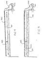
- the overdrive wheels movement is stopped when most of the printout is advanced out of the printer, e.g. as shown in Figure 1 .
- the vacuum source is kept on for the required time to dry the medium, so holding only an end region of the medium 130, preferably having length equal to the width of the medium 130 and about 50 mm in the media axis direction X.
- the vacuum is switched off to drop the medium 130, e.g. into a conventional collecting bin, not shown.
- the same holddown system e.g. having one platen and one vacuum source
- the same holddown system may be capable of being employed to perform a plurality different operations, such as loading and feeding operation, printing operation and outputting operation.
- each of this operations may be performed also using independent holddown systems, i.e. independent holddown surfaces and/or independent vacuum source.
- independent holddown systems i.e. independent holddown surfaces and/or independent vacuum source.
- the skilled in the art is now aware that only some of those operations may be performed by means of a vacuum holddown system while the remaining ones may be performed employing conventional systems.
Landscapes
- Handling Of Sheets (AREA)
- Lining Or Joining Of Plastics Or The Like (AREA)
- Handling Of Cut Paper (AREA)
- Delivering By Means Of Belts And Rollers (AREA)
- Separation, Sorting, Adjustment, Or Bending Of Sheets To Be Conveyed (AREA)
Claims (10)
- Eine Druckkopievorrichtung, die eine Medienniederhalteeinheit (200) aufweist, wobei eine solche Niederhalteeinheit (200) eine Platte (400) und eine Vakuumquelle (700) zum Erzeugen eines negativen Drucks auf zumindest einem Teil eines Mediums aufweist, das auf der Platte (400) positioniert ist, um den Teil im Wesentlichen flach auf der Platte (400) zu halten, wobei die Niederhalteeinheit zumindest zwei Vakuumkammern (382, 383, 690, 691, 692, 693) aufweist, wobei jede der Vakuumkammern (382, 383, 690, 691, 692, 693) in der Lage ist, einen negativen Druck auf einen unterschiedlichen Teil des Mediums auszuüben, der auf einer entsprechenden unterschiedlichen Region der Platte positioniert ist, dadurch gekennzeichnet, dass die Vorrichtung eine Medienantriebsrolle (300) aufweist, und dadurch, dass alle der zumindest zwei Vakuumkammern in einer kontinuierlichen Luftkommunikation mit der Vakuumquelle (700) sind,
wobei zumindest eine der zumindest zwei Vakuumkammern (690, 691, 692) mit der Vakuumquelle über eine Apertur (660) verbunden ist, die die Luftzirkulation hin zu der Vakuumquelle (700) wesentlich reduziert. - Eine Druckkopievorrichtung gemäß Anspruch 1, bei der der Druck, der in zumindest einer der zwei Kammern (382, 693) erzeugt wird, unabhängig von dem Druck ist, der in der verbleibenden Kammer (383, 690) oder den Kammern erzeugt wird.
- Eine Druckkopievorrichtung gemäß Anspruch 1, bei der der Druck, der in einer Anzahl der zumindest zwei Kammern (383, 690, 691, 692) erzeugt wird, die Gleichmäßigkeit des Drucks in einer anderen Kammer der zumindest zwei Kammern (382, 691, 692, 693) im Wesentlichen nicht beeinflusst.
- Eine Druckkopievorrichtung gemäß einem der vorhergehenden Ansprüche, bei der eine Umgehungsleitung (381, 680, 681, 682) eingesetzt wird, um eine der zumindest zwei Kammern (383, 690, 691, 692) schnittstellenmäßig mit der Vakuumquelle zu verbinden, durch Umgehen der verbleibenden Kammer (832) oder der Kammern (691, 692, 693).
- Eine Druckkopievorrichtung gemäß Anspruch 4, bei der jede außer eine der zumindest zwei Kammern (383, 690, 691, 692) schnittstellenmäßig mit der Vakuumquelle durch eine im Wesentlichen unabhängige Umgehungsleitung (381, 680, 681, 682) verbunden ist.
- Eine Druckkopievorrichtung gemäß einem der vorhergehenden Ansprüche, bei der die Vakuumquelle zumindest einen Lüfter (700) aufweist.
- Eine Druckkopievorrichtung gemäß Anspruch 6, bei der die Vakuumquelle zumindest zwei Lüfter in Reihe aufweist.
- Eine Druckkopievorrichtung gemäß einem der vorhergehenden Ansprüche, bei der im Wesentlichen derselbe Druck auf jeden unterschiedlichen Teil des Mediums ausgeübt wird.
- Ein Verfahren zum Niederhalten eines Mediums, wenn es auf eine Platte in einer Druckkopievorrichtung platziert ist, die eine Vakuumquelle aufweist, wobei das Verfahren folgende Schritte aufweist:Platzieren der Vakuumquelle in eine kontinuierliche und im Wesentlichen unabhängige Luftkommunikation mit einer Anzahl von einzelnen Region der Platte,Positionieren des Mediums, um eine oder mehrere Regionen der Platte abzudecken,Ausüben eines negativen Drucks auf die Rückseite des Mediums über die unabhängige Luftkommunikation zwischen der Vakuumquelle und jeder Region der Platte, die durch das Medium abgedeckt ist, durch zumindest zwei Vakuumkammern, wobei jede in der Lage ist, einen negativen Druck auf eine unterschiedliche Region des Mediums auszuüben,und Bereitstellen einer Apertur zwischen zumindest einer der zumindest zwei Kammern und der Vakuumquelle, um die Luftzirkulation hin zu der Vakuumquelle wesentlich zu Reduzieren.
- Ein Verfahren gemäß Anspruch 9, bei dem der negative Druck im Wesentlichen einheitlich auf die Rückseite des Mediums ausgeübt wird.
Priority Applications (3)
| Application Number | Priority Date | Filing Date | Title |
|---|---|---|---|
| EP19990102977 EP0997308B1 (de) | 1998-10-30 | 1999-02-15 | Druckgerät und Verfahren zur Erzeugung eines gleichmässigen Druckes zum Niederhalten von Druckmedien |
| US09/429,433 US6367999B1 (en) | 1999-02-15 | 1999-10-28 | Hardcopy apparatus and method for providing uniform pressure to hold down media |
| JP11309265A JP2000135828A (ja) | 1998-10-30 | 1999-10-29 | 媒体押さえ可能なハ―ドコピ―装置 |
Applications Claiming Priority (3)
| Application Number | Priority Date | Filing Date | Title |
|---|---|---|---|
| EP98120706 | 1998-10-30 | ||
| EP98120706A EP0997302B1 (de) | 1998-10-30 | 1998-10-30 | Bilderzeugungsgerät und Verfahren zum Niederhalten von Aufzeichnungsträgermaterial |
| EP19990102977 EP0997308B1 (de) | 1998-10-30 | 1999-02-15 | Druckgerät und Verfahren zur Erzeugung eines gleichmässigen Druckes zum Niederhalten von Druckmedien |
Publications (3)
| Publication Number | Publication Date |
|---|---|
| EP0997308A2 EP0997308A2 (de) | 2000-05-03 |
| EP0997308A3 EP0997308A3 (de) | 2000-10-25 |
| EP0997308B1 true EP0997308B1 (de) | 2009-02-04 |
Family
ID=26149760
Family Applications (1)
| Application Number | Title | Priority Date | Filing Date |
|---|---|---|---|
| EP19990102977 Expired - Lifetime EP0997308B1 (de) | 1998-10-30 | 1999-02-15 | Druckgerät und Verfahren zur Erzeugung eines gleichmässigen Druckes zum Niederhalten von Druckmedien |
Country Status (2)
| Country | Link |
|---|---|
| EP (1) | EP0997308B1 (de) |
| JP (1) | JP2000135828A (de) |
Families Citing this family (8)
| Publication number | Priority date | Publication date | Assignee | Title |
|---|---|---|---|---|
| EP1182040B1 (de) * | 2000-08-24 | 2005-11-23 | Hewlett-Packard Company, A Delaware Corporation | Spannapparatur für Drucker |
| CN1757518A (zh) | 2004-10-04 | 2006-04-12 | 奥西-技术有限公司 | 用于宽幅薄片的薄片处理装置 |
| EP1642735B1 (de) * | 2004-10-04 | 2015-05-13 | Océ-Technologies B.V. | Grossformatige Bogenhandhabungsvorrichtung |
| EP1642728B1 (de) * | 2004-10-04 | 2009-05-06 | Océ-Technologies B.V. | Vorrichtung zum Handhaben von Bögen |
| DE602005014315D1 (de) * | 2004-10-04 | 2009-06-18 | Oce Tech Bv | Vorrichtung zum Handhaben von Bögen |
| JP4936708B2 (ja) * | 2004-11-25 | 2012-05-23 | オセ−テクノロジーズ ビーブイ | 印刷面及び送り板を有するシート処理装置 |
| JP5987362B2 (ja) | 2012-03-02 | 2016-09-07 | セイコーエプソン株式会社 | 液体噴射装置 |
| US20140085390A1 (en) * | 2012-09-27 | 2014-03-27 | Timothy J. Young | Vacuum pulldown of web in printing systems |
Family Cites Families (3)
| Publication number | Priority date | Publication date | Assignee | Title |
|---|---|---|---|---|
| US3584954A (en) * | 1968-11-18 | 1971-06-15 | Robert Nast | Vacuum enlarger easel |
| JPH0329352U (de) * | 1989-07-19 | 1991-03-22 | ||
| US5414491A (en) * | 1994-02-14 | 1995-05-09 | Eastman Kodak Company | Vacuum holder for sheet materials |
-
1999
- 1999-02-15 EP EP19990102977 patent/EP0997308B1/de not_active Expired - Lifetime
- 1999-10-29 JP JP11309265A patent/JP2000135828A/ja not_active Withdrawn
Also Published As
| Publication number | Publication date |
|---|---|
| JP2000135828A (ja) | 2000-05-16 |
| EP0997308A3 (de) | 2000-10-25 |
| EP0997308A2 (de) | 2000-05-03 |
Similar Documents
| Publication | Publication Date | Title |
|---|---|---|
| EP0997306B1 (de) | Papierbildervorrichtung und Datenträgerausgabeverfahren | |
| US7744210B2 (en) | Moving floor media transport for digital printers | |
| US6367999B1 (en) | Hardcopy apparatus and method for providing uniform pressure to hold down media | |
| EP0997302B1 (de) | Bilderzeugungsgerät und Verfahren zum Niederhalten von Aufzeichnungsträgermaterial | |
| US20070165092A1 (en) | Ink jet recording apparatus | |
| US6786664B2 (en) | Active vacuum roller and method for advancing media | |
| US6682190B2 (en) | Controlling media curl in print-zone | |
| GB2351703A (en) | Post-print bending of a sheet of paper following inkjet printing thereon to reduce paper cockle | |
| EP0997308B1 (de) | Druckgerät und Verfahren zur Erzeugung eines gleichmässigen Druckes zum Niederhalten von Druckmedien | |
| EP1721750A1 (de) | Hilfsvorrichtung zur Halterung eines Mediums in einem schrittweisen Transportsystem eines digitalen Druckers | |
| EP3251989B1 (de) | Bahnwicklung mit reibungsbedingter anspannung | |
| EP1022147B1 (de) | Medientransportsystem | |
| EP0997307B1 (de) | Papierbildervorrichtung und Datenträgereinführverfahren | |
| US20100020150A1 (en) | Vacuum platen for an image forming apparatus | |
| JP2001268310A (ja) | 画像形成装置及びロール状記録媒体切断方法 | |
| US20190308426A1 (en) | Feeding a print medium and printer | |
| US6565081B1 (en) | Media outputting device and method for outputting media | |
| US11141991B2 (en) | Inkjet printing device | |
| JP2003260839A (ja) | 画像記録装置 | |
| US8985761B2 (en) | Printer assembly | |
| JP2018030320A (ja) | インクジェットプリンタ及びキャリッジの移動制御方法 | |
| JP2003291431A (ja) | プリンタ | |
| JPH09239965A (ja) | インクジェット方式画像形成装置 |
Legal Events
| Date | Code | Title | Description |
|---|---|---|---|
| PUAI | Public reference made under article 153(3) epc to a published international application that has entered the european phase |
Free format text: ORIGINAL CODE: 0009012 |
|
| AK | Designated contracting states |
Kind code of ref document: A2 Designated state(s): DE ES FR GB IT NL |
|
| AX | Request for extension of the european patent |
Free format text: AL;LT;LV;MK;RO;SI |
|
| PUAL | Search report despatched |
Free format text: ORIGINAL CODE: 0009013 |
|
| AK | Designated contracting states |
Kind code of ref document: A3 Designated state(s): AT BE CH CY DE DK ES FI FR GB GR IE IT LI LU MC NL PT SE |
|
| AX | Request for extension of the european patent |
Free format text: AL;LT;LV;MK;RO;SI |
|
| RAP1 | Party data changed (applicant data changed or rights of an application transferred) |
Owner name: HEWLETT-PACKARD COMPANY, A DELAWARE CORPORATION |
|
| 17P | Request for examination filed |
Effective date: 20010425 |
|
| AKX | Designation fees paid |
Free format text: DE ES FR GB IT NL |
|
| 17Q | First examination report despatched |
Effective date: 20040902 |
|
| GRAP | Despatch of communication of intention to grant a patent |
Free format text: ORIGINAL CODE: EPIDOSNIGR1 |
|
| GRAS | Grant fee paid |
Free format text: ORIGINAL CODE: EPIDOSNIGR3 |
|
| GRAA | (expected) grant |
Free format text: ORIGINAL CODE: 0009210 |
|
| AK | Designated contracting states |
Kind code of ref document: B1 Designated state(s): DE ES FR GB IT NL |
|
| REG | Reference to a national code |
Ref country code: GB Ref legal event code: FG4D |
|
| REF | Corresponds to: |
Ref document number: 69940377 Country of ref document: DE Date of ref document: 20090319 Kind code of ref document: P |
|
| PGFP | Annual fee paid to national office [announced via postgrant information from national office to epo] |
Ref country code: NL Payment date: 20090224 Year of fee payment: 11 |
|
| NLV1 | Nl: lapsed or annulled due to failure to fulfill the requirements of art. 29p and 29m of the patents act | ||
| PG25 | Lapsed in a contracting state [announced via postgrant information from national office to epo] |
Ref country code: NL Free format text: LAPSE BECAUSE OF FAILURE TO SUBMIT A TRANSLATION OF THE DESCRIPTION OR TO PAY THE FEE WITHIN THE PRESCRIBED TIME-LIMIT Effective date: 20090204 Ref country code: ES Free format text: LAPSE BECAUSE OF FAILURE TO SUBMIT A TRANSLATION OF THE DESCRIPTION OR TO PAY THE FEE WITHIN THE PRESCRIBED TIME-LIMIT Effective date: 20090515 |
|
| REG | Reference to a national code |
Ref country code: FR Ref legal event code: ST Effective date: 20091030 |
|
| PLBE | No opposition filed within time limit |
Free format text: ORIGINAL CODE: 0009261 |
|
| STAA | Information on the status of an ep patent application or granted ep patent |
Free format text: STATUS: NO OPPOSITION FILED WITHIN TIME LIMIT |
|
| 26N | No opposition filed |
Effective date: 20091105 |
|
| PG25 | Lapsed in a contracting state [announced via postgrant information from national office to epo] |
Ref country code: FR Free format text: LAPSE BECAUSE OF NON-PAYMENT OF DUE FEES Effective date: 20090406 |
|
| PG25 | Lapsed in a contracting state [announced via postgrant information from national office to epo] |
Ref country code: IT Free format text: LAPSE BECAUSE OF FAILURE TO SUBMIT A TRANSLATION OF THE DESCRIPTION OR TO PAY THE FEE WITHIN THE PRESCRIBED TIME-LIMIT Effective date: 20090204 |
|
| REG | Reference to a national code |
Ref country code: DE Ref legal event code: R082 Ref document number: 69940377 Country of ref document: DE Representative=s name: SCHOPPE, ZIMMERMANN, STOECKELER, ZINKLER & PAR, DE |
|
| REG | Reference to a national code |
Ref country code: DE Ref legal event code: R082 Ref document number: 69940377 Country of ref document: DE Representative=s name: SCHOPPE, ZIMMERMANN, STOECKELER, ZINKLER & PAR, DE Effective date: 20120229 Ref country code: DE Ref legal event code: R081 Ref document number: 69940377 Country of ref document: DE Owner name: HEWLETT-PACKARD DEVELOPMENT COMPANY, L.P., HOU, US Free format text: FORMER OWNER: HEWLETT-PACKARD CO. (N.D.GES.D.STAATES DELAWARE), PALO ALTO, CALIF., US Effective date: 20120229 |
|
| REG | Reference to a national code |
Ref country code: GB Ref legal event code: 732E Free format text: REGISTERED BETWEEN 20120329 AND 20120404 |
|
| PGFP | Annual fee paid to national office [announced via postgrant information from national office to epo] |
Ref country code: GB Payment date: 20130129 Year of fee payment: 15 Ref country code: DE Payment date: 20130124 Year of fee payment: 15 |
|
| REG | Reference to a national code |
Ref country code: DE Ref legal event code: R119 Ref document number: 69940377 Country of ref document: DE |
|
| GBPC | Gb: european patent ceased through non-payment of renewal fee |
Effective date: 20140215 |
|
| REG | Reference to a national code |
Ref country code: DE Ref legal event code: R119 Ref document number: 69940377 Country of ref document: DE Effective date: 20140902 |
|
| PG25 | Lapsed in a contracting state [announced via postgrant information from national office to epo] |
Ref country code: DE Free format text: LAPSE BECAUSE OF NON-PAYMENT OF DUE FEES Effective date: 20140902 Ref country code: GB Free format text: LAPSE BECAUSE OF NON-PAYMENT OF DUE FEES Effective date: 20140215 |