EP0997308B1 - Hardcopy apparatus and method for providing uniform pressure to hold down media - Google Patents
Hardcopy apparatus and method for providing uniform pressure to hold down media Download PDFInfo
- Publication number
- EP0997308B1 EP0997308B1 EP19990102977 EP99102977A EP0997308B1 EP 0997308 B1 EP0997308 B1 EP 0997308B1 EP 19990102977 EP19990102977 EP 19990102977 EP 99102977 A EP99102977 A EP 99102977A EP 0997308 B1 EP0997308 B1 EP 0997308B1
- Authority
- EP
- European Patent Office
- Prior art keywords
- medium
- vacuum
- platen
- chambers
- vacuum source
- Prior art date
- Legal status (The legal status is an assumption and is not a legal conclusion. Google has not performed a legal analysis and makes no representation as to the accuracy of the status listed.)
- Expired - Lifetime
Links
Images


Classifications
-
- B—PERFORMING OPERATIONS; TRANSPORTING
- B41—PRINTING; LINING MACHINES; TYPEWRITERS; STAMPS
- B41J—TYPEWRITERS; SELECTIVE PRINTING MECHANISMS, i.e. MECHANISMS PRINTING OTHERWISE THAN FROM A FORME; CORRECTION OF TYPOGRAPHICAL ERRORS
- B41J11/00—Devices or arrangements of selective printing mechanisms, e.g. ink-jet printers or thermal printers, for supporting or handling copy material in sheet or web form
- B41J11/0085—Using suction for maintaining printing material flat
-
- B—PERFORMING OPERATIONS; TRANSPORTING
- B41—PRINTING; LINING MACHINES; TYPEWRITERS; STAMPS
- B41J—TYPEWRITERS; SELECTIVE PRINTING MECHANISMS, i.e. MECHANISMS PRINTING OTHERWISE THAN FROM A FORME; CORRECTION OF TYPOGRAPHICAL ERRORS
- B41J13/00—Devices or arrangements of selective printing mechanisms, e.g. ink-jet printers or thermal printers, specially adapted for supporting or handling copy material in short lengths, e.g. sheets
- B41J13/10—Sheet holders, retainers, movable guides, or stationary guides
- B41J13/22—Clamps or grippers
- B41J13/223—Clamps or grippers on rotatable drums
- B41J13/226—Clamps or grippers on rotatable drums using suction
Landscapes
- Handling Of Sheets (AREA)
- Lining Or Joining Of Plastics Or The Like (AREA)
- Handling Of Cut Paper (AREA)
- Delivering By Means Of Belts And Rollers (AREA)
- Separation, Sorting, Adjustment, Or Bending Of Sheets To Be Conveyed (AREA)
Description
- The present invention generally relates to hardcopy apparatus, such as copiers, printers, scanners, facsimiles, and more particularly to improved media holddown devices for such apparatus.
- To reduce the effects of paper curl and cockle on dot placement during printing, conventional practice is to employ sheet holddown devices such as electrostatic or suction devices. Cockle effect is the reluctance of the paper to bend smoothly. Instead it bends locally in a sharp fashion, creating permanent wrinkles.
- In an electrostatic holddown device, for example, paper flatness is maintained by establishing electrostatic attraction between a flat support plate on the printer and the back surface of a sheet to be printed. Likewise, in vacuum holddown devices, sheet flatness is maintained by providing suction between a support plate and the back surface of a sheet to be printed. It should be noted that, in either type of holddown device, direct contact of the holddown device with the printed surface is avoided to minimise ink smearing and other adverse affects on print appearance.
- Although conventional vacuum holddown devices are fairly effective in maintaining sheet flatness during printing, they have drawbacks. One drawback is the complexity of maintaining the same holddown force along the entire width of the medium while printing, i.e. in the direction of the printheads motion. This is due to the losses of air that the conventional devices allow, causing the medium to be subject to different forces, i.e. forcing the medium to rotate while it is advanced in the direction of the media motion.
- This is particularly true in case of a large format printer, prior art printers, like ENCAD PROe, a 60" wide printer, having a single vacuum channel/chamber extending along the entire platen may cause a number of drawbacks.
- In fact, increasing the size of the platen implies the increase of the number of different media sizes which might be handled by the same printer. For instance, a printer having a platen 60'' wide may be used to handle not only media of the same nominal size, i.e. 60'', but also smaller width such as: 50'', 42'', 24'' or down to 8.5''.
- So, when a medium having a smaller size in placed on the platen of such a printer two results may be obtained:
- a) the vacuum holddown system is capable of apply enough negative pressure to the back of the medium to keep it flat on the platen, but due to the losses of air generated in the part of the platen not covered by the medium, the pressure is applied not uniformly in the printhead motion direction;
- b) the dimension of the air losses caused by the smaller medium is so big that the air flow generated in the vacuum chamber not allow to apply a negative pressure to the back of the medium, sufficient to hold the medium flat on the platen.
- A known method to overcome this problem has been disclosed in Falcon Color RJ-800C full color inkjet plotter available from Mutoh Industries Ltd.
- This printer employs a single vacuum chamber connected to a fan having at the end, further from the fan, a wall which is slidable in a horizontal direction to increase or reduce the dimension of the vacuum chamber itself. A pinch roller is mounted on this wall, to engage a border of the medium. The opposite border of the media is engaged by a second fixed pinch roller, located at one end of the print zone. When a medium having a different size is loaded in the printer, the fixed pinch roller engage one side of the medium, while the other pinch roller is slid laterally in one or the other direction to engage the other side of the medium. By moving the pinch roller, the wall is slid too, so that the vacuum chamber result in being fully covered by the medium and thus reducing to the minimum the air losses that may cause the above drawbacks.
- However, this arrangement requires manual engagement of the medium, which may result in damages to medium (ink transfer from hands to the medium or wrong engagement operation), loss of time, or wear of the wall which may cause substantial air losses.
-
US5414491 andUS3584954 disclose hardcopy apparatuses according to the preamble ofclaim 1 comprising a valve or a mechanical actuator for selectively communicating the vacuum chambers with the vacuum source. The present invention seek to provide an improved hardcopy apparatus and method of holding down a medium in the hardcopy apparatus. - According to an aspect of the present invention there is provided a hardcopy apparatus according to
claim 1. - This allows the hardcopy apparatus to handle a large variety of media sizes without affecting the capability of providing a fast, simple and clean loading system for the apparatus. Furthermore no manual movement of mechanical parts of the apparatus is required when a medium having different size from the previous one is loaded.
- In addition, the present invention can be particularly suitable to inkjet printers which preferably require a media to be periodically accurately indexed across a print zone defined in the printer for receiving the ink.
- Preferably, the pressure generated in at least one of the two chambers is independent from the pressure generated in the remaining chamber or chambers. More preferably, the pressure generated in a number of the at least two chambers is substantially not affecting the uniformity of the pressure in another chamber of the at least two chambers.
- In a preferred embodiment, a bypass conduit is employed to interface one of the at least two chambers to the vacuum source by passing the remaining chamber or chambers. Moreover, each but one of the at least two chambers is interfaced to the vacuum source by a substantially independent bypass conduit.
- This helps to reduce any substantial air interference with the remaining vacuum chambers, so that a more uniform negative pressure can be applied to the back of the medium.
- According to the invention, at least one of the at least two chambers is connected to the vacuum source via an aperture, substantially reducing the air circulation toward the vacuum source.
- The reduction of air circulation in the chamber helps the vacuum source to generate higher depression in the vacuum chambers.
- Preferably, the vacuum source comprises at least a fan and more preferably at least two fans in series, for maintaining a smaller diameter of the fan but increasing the total power of the vacuum source.
- Typically, substantially the same pressure is applied to each different portion of the medium.
- Viewing another aspect of the present invention there is provided a method for holding down a medium when placed on a platen in a hardcopy apparatus, according to claim 9.
- Preferably, said negative pressure is substantially uniformly applied to the back of the medium.
- The present invention will be described further, by way of example only, with reference to an embodiment thereof as illustrated in the accompanying drawings in which:
-
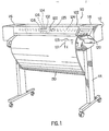
Figure 1 is a perspective view of an inkjet printer incorporating the features of the present invention; -
Figure 2 is a more detailed diagram of a holddown system within the printer ofFigure 1 ; -
Figure 3 depicts portion of a first example of the holddown system ofFigure 2 ; -
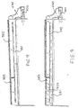
Figure 4 is a section of the main hardware components of the holddown system ofFigure 3 . -
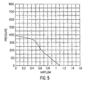
Figure 5 depicts a test curse of nominal values of the pressure applied a medium vs. air flow provided by a vacuum device, employed in the holddown system ofFigure 3 , in the rated voltage of 24 V; -
Figure 6 depicts the vacuum channel structure of the holddown system ofFigure 3 ; -
Figures 7 ,8 and 9 are a diagram views about how the air flow is circulating within the vacuum channels of the holddown system ofFigure 3 . -
Figure 10 depicts the vacuum of a second example structure of the holddown system. - Referring to
Figure 1 , aprinter 110 includes ahousing 112 mounted on astand 114. The housing has left and rightdrive mechanism enclosures control panel 120 is mounted on theright enclosure 118. Acarriage assembly 100 illustrated in phantom under acover 122, is adapted for reciprocal motion along acarriage bar 124, also shown in phantom. Thecarriage assembly 100 comprises fourinkjet printheads carriage assembly 100 translates relative to themedium 130 along the X and Y axis, selected nozzles of theprintheads medium 130. The colours from the three colour printheads are mixed to obtain any other particular colour. The position of thecarriage assembly 100 in a horizontal or carriage scan axis (Y) is determined by a carriage positioning mechanism with respect to an encoder strip. (not shown). Aprint medium 130 such as paper is positioned along a vertical or media axis by a media axis mechanism (not shown). As used herein, the media axis is called the X axis denoted as 101, and the scan axis is called the Y axis denoted as 103. - Referring now to
Figure 2 , an holddown system is globally referenced as 200. Such aholddown system 200 is located between the left and rightdrive mechanism enclosures holddown system 200 will be made further with reference toFigure 3 . Theinkjet printheads movable carriage 100 so that the printhead nozzles are above the surface of a portion of the medium 130 which lays substantially flat on a flatstationary support platen 400 of saidholddown system 200. - With reference to
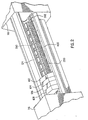
Figure 3 , theflat platen 400 is shown in more details, and is located in a front position of theprinter 110 and co-operate with amain driving roller 300, in the following identified also as the main roller, located in a rear position, and a plurality ofpinch wheels 310, in this example 12pinch wheels 310 are employed, which are controlled to periodically index or convey the medium across the surface of theplaten 400. The force between each pinchwheels 310 and themain roller 300 is comprised between 3.33 N and 5 N, preferably 4.15 N. - This pinch wheel distribution and force helps to drive the medium 130 straight with irrelevant lateral slippage, to share the medium 130 expansion on all its width. In fact has been observed that printers with low forces, e.g. about 1 N, allow media expansion accumulates in a particular place and this may cause a wrinkle to get so big to create a crash of the printhead.
- The
main roller 300 is provided with a conventional surface having a plurality ofcircumferencial recesses 305 housing a corresponding plurality ofprotrusions 405 of theplaten 400 extending towards the rear of theprinter 110. This combination of features allows the medium 130 to reliably move from themain roller 300 to theplaten 400 and vice versa. In fact the gap between theroller 300 and theplaten 400 may allow an edge of the medium to engage the back of the platen itself causing a paper jam. - The
printer 110 comprises, a vacuum source, in this case afan 700 shown inFigure 7 , connected to the atmosphere through a plurality of holes, or apertures, 330, 350 and a vacuum chamber globally referred as 380; such vacuum source generates an air flow by sucking air from the atmosphere. - Referring also to
Figure 6 and7 , the structure of thevacuum channel 380 will be described in more details. A connectingconduit 650 is connecting thefan 700 to thevacuum channel 380 which extends below theplaten 400 along all the print zone of the printer.Such vacuum channel 380 comprises a plurality of vacuum chambers, each one has been designed as to maintain a certain negative pressure, or allowing a certain air circulation, in the chamber without substantially affecting any air flow or negative pressure which may be present in other chambers. InFigures 3 and6 to 9,vacuum channel 380 comprises 2chambers close conduit 650 to thesame fan 700. - The
first chamber 382 is straightly laying directly below a first region of the platen which in this example is wide 24'' in the scan axis direction. - The
second chamber 383 lays next, but separated by awall 385, to thefirst chamber 382 and extend it to the end of the platen. Thesecond chamber 383 is straightly laying directly below a second region of the platen, which is, in this example 12'' wide in the scan axis direction. Abypass conduit 381 extends below thefirst chamber 382 and thesecond chamber 383 for all the width of theplaten 400, putting in communication thesecond chamber 383 with the connectingconduit 650. - According to this example, the
second chamber 383, 12'' wide, and the first chamber, 24'' wide, provide the 36''platen 400 with vacuum along its complete extension. - Referring back to
Figure 3 , - Due to the pressure differential between atmosphere pressure on the surface of the medium 130 and the vacuum applied through the
vacuum channel 380 and theholes holes platen 400. - In order to reduce the losses of air from the
vacuum channel 380, theholes first holes 330 lays in a line at a distance comprised between 10 mm and 30 mm, preferably 19 mm and a plurality ofsecondary holes 350, distributed preferably in line. - Furthermore, the
platen 400 is provided, according to this preferred example, with a plurality of substantially linear grooves having one end closer to and the opposed end further from themain roller 300. Such grooves are linked together to form acontinuos slot 320, which crosses substantially the whole width of theplaten 400, where such acontinuous slot 320 is arranged to have a waved shape. - The plurality of first holes, or slot
holes 330, having a diameter comprises between 1.5 mm and 3.5 mm, preferably about 2.5 mm, are then distributed inside the wavedslot 320, and in this embodiment are preferably located in the further part of theslot 320 with respect to themain roller 300. - The size of the vacuum channel is a further parameter relevant to apply the proper vacuum to the back of the medium. Experiments run by the Applicant have shown that the surface of the sum of the squared sections of the
vacuum chambers Figure 3 , is preferably bigger than the sum of the surface of all theapertures platen 400. More preferably the sum of the sections of thechambers apertures bypass conduit 381 is providing a better approximation, since is this dimension which is actually influencing the air flow speed or the amount of negative pressure available in the second chamber. As shown into the drawings, the section of thebypass conduit 381 is smaller than the section of the first chamber 282 since thefirst chamber 382 is connected to atmosphere through a first group of holes (first andsecondary holes 330, 350) distributed on 24" of platen, while thebypass conduit 381 is connected to the atmosphere through thesecond chamber 383 and a second group of holes (first andsecondary holes 330, 350) distributed on the remaining 12'' of platen. - Referring to
Figure 7 , the behaviour of the vacuum unit is shown. When thefan 700 is operating and no media is placed on theplaten 400, air is sucked through thevarious holes platen 400 and two substantially independent air flows are generated. A first air flow 710 is guided within thefirst vacuum chamber 382 while asecond air flow 720 is guided within thesecond vacuum chamber 383 and thevacuum bypass 381, both towards thefan 700. The twoair flows 710, 720 are mixed together at the entrance into the connectingconduit 650 and finally end in the fan, which expulses the sucked air into the atmosphere again. According to the drawings the air flows mixes at the very end ofchannel 380 and this cause a small loss of pressure in the pressure generation. However, because the length of thebypass 383 and thefirst chamber 382 compared to the length of the zone where the two air flows are mixed is very big, the non-uniformity would be hardly noticeable. - With reference to
Figure 8 , a 24'' size medium is placed onto the platen, in correspondence of thefirst vacuum chamber 382 and covering all the apertures of the platen available in the first region. Thus, in thefirst chamber 382 the first air flow 710 becomes of negligible intensity and the action of the fan is converted into a uniform negative pressure applied to the back of the medium. At the same time, being the apertures in the second region of theplaten 400 still free from obstacles, thesecond air flow 720, is still free to circulate in thevacuum channel 380, but only through thesecond chamber 383, thebypass 381, without substantially affecting the uniformity of the pressure provided in thefirst chamber 382. - With reference to
figure 9 , a 36" size medium is placed onto the platen, in correspondence of both the vacuum chambers and closing all the apertures available in the first and the second regions of theplaten 400. In this case a uniform negative pressure is generated in all thevacuum channel 380, i.e. in the first andsecond vacuum chambers bypass 381. - The length of both chambers as well as the power of the vacuum has been carefully dimensioned in order to allow a big variety of media sizes to be loaded onto the printer.
- For instance if a sheet of 8.5'' (A4 size) is loaded on the first region of the platen a certain number of free apertures (not covered by the sheet) allows the generation of an air flow in the first chamber. However, thanks to the reduced dimension of the chamber (24" and not 36") the
fan 700 is still able to provide the back of the sheet with sufficient uniform negative pressure for correct operations. - Referring now to
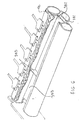
Fig. 10 , in an embodiment of the invention, e.g. a printer 60'' wide, the platen is be divided into 4 regions,, placed side by side in the scan axis direction, having sizes equal to 36'', 6", 8'' and 6'', to more precisely handle medium having sizes of 36'', 42'', 54" and 60''. - As in the previous example, the
vacuum channel 380 comprises 4 vacuum chambers, 690, 691, 692, 693, distributed side by side, and separated each other by awall 685, having width of 36'', 6", 8'', 6''; each region is placed in correspondence of one of the 4 regions defined on theplaten 400. In this case all the vacuum chambers are connected to thevacuum conduit 650, each one, but thevacuum chamber 693 closer to the vacuum source, by means of an independent bypass conduit, 680, 681, 682. -
Figure 10 shows how thedifferent bypass conduits - Thus, to reduce the amount of air that goes into the fan each vacuum chamber is connected to its bypass conduit by means of a
narrow bypass aperture 660. In this way if no air flow is generated (the medium covers the apertures on the platen) there are no pressure losses. When there is some air flow, the bypass aperture is so small that the pressure losses grow very rapidly, thus making the air flow through (and so towards the fan) it very small. - In this case, since there is a wider
first vacuum chamber 693 and it is still required that sufficient negative pressure is applied to the back of media of small size (e.g. 8.5''), the vacuum source has an increase power. For instance the vacuum source may comprises a first and a second fans, placed in series, both of the same power of the one employed in the first example. However, such fans may also placed in parallel. This allows to obtain an increased power but maintaining the same small diameter of the fan. - In a further embodiment, the vacuum channel comprises an increased number of independent vacuum chambers of limited dimensions, connected to the atmosphere through the plurality of apertures provided on the
platen 400. Each independent chamber is also connected to a bigger common vacuum conduit via an additional narrow aperture. The vacuum source is directly connected to said common vacuum conduit. - Due to the reduced dimension of the additional apertures connecting the independent chambers to the common conduit, a very limited air flow is generate in the common conduit even when no media is placed on the platen apertures relative to an independent chamber. Thus, the common vacuum conduit is capable to maintain a uniform negative pressure also when an independent chamber have pressure equal to 0 (no media is present on top of it) or to provide an independent chamber with substantially its same pressure when its corresponding platen apertures are closed by media.
- Returning to
Figure 3 , it is important to note that since themain roller 300 is not included within thevacuum channel 380, the vacuum can be only directly generated at a certain distance from themain roller 300 itself. However, if theslot 320 is included in the unit, when the vacuum source is activated and in presence of a medium on theplaten 400, the vacuum can be expanded along all the slot extending the vacuum closer to themain roller 300. - In this application extending the vacuum means that the vacuum generated at one aperture, which is normally supplied to an area of the back of medium, is now supplied to an area of the back of the medium which is at least 10% bigger, preferably bigger than 500%.
- This helps in more uniformly apply the vacuum to the back of the medium, reducing the risk of having peak of vacuum that may crease the medium. Furthermore, thanks to the
slot 320 there is no need to conventionally include themain roller 300 into thevacuum channel 380 and this means that: a) the air losses are minimised, since in conventional systems, having the main roller included in the vacuum channel, most of the air is lost around the main roller itself; b) the air flow is forwarded towards themain roller 300, meaning that aprint zone 450 can be defined closer to themain roller 300; and c) the dimensions of the vacuum channel can be better controlled, giving more design freedom for designing the holddown system. - According to the above, it is possible to print closer to the edges of a cut medium. In fact the medium can still be indexed by the
main roller 300 and thepinch rollers 310 even when we are printing close to the very end of the medium itself. - Applicant's extended tests have revealed that a width too wide of the slot can reduce the capability of maintaining the medium substantially flat while printing, so affecting the printing quality. On the contrary, a width too narrow and/or an insufficient depth may affect the air flow direction, i.e. the vacuum force is not extended close enough to the
main roller 300. - Furthermore, high vacuum may crease the paper especially if the grooves of the
slot 320 are wide and run parallel to the paper advance direction. Therefore is advisable to run the grooves at about 45° respect to the media axis X and optimise the slot width to minimise creases in the paper and to evenly distribute the vacuum. In addition, if the groove is parallel to the advance direction, it may make the ink to migrate and create localised dark areas. - This means that it is not necessary that the plurality of grooves are linked together in order to form a continuous slot for achieving the above advantage.
- Accordingly, the
slot 320 has a depth deeper than 0.5 mm, preferably 1 mm, and a width comprises between 3 mm and 8 mm, preferably 5 mm. - However, the continuous shape of the waved
slot 320 helps theholddown system 200 to evenly distribute the vacuum along theprint zone 450. In fact, an interrupted sequence of grooves may create areas, having a reduced vacuum, which cross thecomplete print zone 450, in the media axis direction X. This may force the ink applied in those areas to migrate and create localised dark or clear portions in the printout. - Further from the waved
slot 320, along the media axis (X), theplaten 400 is provided with a plurality of secondary recesses 360, distributed in one line along the scan axis (Y). In this example each recess 360 is composed by two parts, a first one substantially squared and a second one substantially triangular, where the triangular part lays on a plane which deeper than the plane on which the squared part lays. - Furthermore, each squared part is provided with a
secondary hole 350, having a diameter comprises between 1.5 and 2.5 mm, preferably 2.0. Such sequence of secondary recesses 360 is combined with a sequence ofoverdrive wheels 340, forming asecondary roller 345, such that a group of 3 consecutive secondary recesses 360 is disposed between twoconsecutive wheels 340. Such a secondary roller is housed in thevacuum channel 380. - Thus, this
holddown system 200 comprises 12overdrive wheels 340 equally separated along the scan axis (Y) to supply equal traction to each part of the medium. - In this description an overdrive wheel may mean a single wheel as well as a plurality of wheels in strict contact one to another, in order to build a wheel having a larger width.
- A secondary recess 360 is distanced by each adjacent element, both a further secondary recess 360 or a
wheel 340, by arib 370. The ribs are employed to reduce the risk of generating cockle wrinkles which may extend towards theprint zone 450. - Accordingly, two
consecutive ribs 370, having a preferably height of 1 mm, are distanced one to another by a distance comprised between 15 mm and 25 mm, preferably about 20 mm if the tworibs 370 are separated by a secondary recess 360. - The plurality of
secondary holes 350 provides thevacuum channel 380 with further apertures for the air flow generated by the vacuum source. - Since the air flow between the top of the
platen 400 and the back of the medium 130 may generate noise in correspondence of thesecondary holes 350, the particular shape of the recesses 360 helps to provide the air flow with a smooth transition, reducing the resulting noise. - As for the slot holes 330, the vacuum generated in correspondence of the
secondary holes 350 is extended, in order to apply a negative pressure to most of the medium 130 laying on theplaten 400. The vacuum is extended particularly due to the presence of theoverdrive wheels 340, and theribs 370, which create a larger empty space between the medium 130 and theplaten 400. - Furthermore, the design of this part of the holddown system helps the printer to reduce the cockle effect on the printout.
- Tensioning the paper in the feeding direction intuitively does not help, because cockle wrinkles mainly extend in the feeding direction as well. Anyway, overdrive forces can reduce the height reached by the cockle wrinkles by as much as a half. In addition, it was noted how the paper works in compression, some very thin papers may even buckle and create loops between the
main roller 300 and the print zone. - This means that the presence of a
secondary roller 345, having the function of tensioning the paper during the printing operation, may help in controlling the occurrence of the cockle wrinkles in the printout. - However, it should be kept in mind that such a
secondary roller 345 provide theprinter 110 with more capabilities, which will be described further. - In this portion of the
platen 400, vacuum is furnished through the plurality ofholes 350 and the gap between eachoverdrive wheel 340 and its surrounding portion of theplaten 400. - Vacuum is used to provide the force between medium and
overdrive wheels 340; the design has been done in such a way that it can provide the required force to theoverdrive wheel 340, preferably comprised between 0.6 N and 1 N, in this example 0.8 N per eachwheel 340, without employing starwheels. Elimination of starwheels is an important issue since it helps to avoid a) the risk of damaging the printout with starwheel marks, b)the need to employ a mechanism or a structure to hold the starwheels themselves. - In addition, according to this example, in order to transmit the proper traction force to the medium, the overdrive interference, i.e. the distance between the surface of the
platen 400 and the top of the aoverdrive roller 340, is preferably maintained between 0.3 mm and 0.6 mm. Below 0.25 mm the traction falls quickly, towards zero traction at zero interference; if the interference is bigger than 0.65 mm, wrinkles created by theoverdrive roller 340 can extend to theprint zone 450. - In
Figures 2 and3 it is also shown afirst reference sign 390, according to this example, in the form of a phantom line, but any kind of suitable reference can be employed, e.g. a continuous or dotted line. Thisfirst reference 390 is traversing all theplaten 400 from the right to the left side in the scan axis (Y) direction. Preferably thefirst reference 390 is tangent to theslot 320, on the side closer to themain roller 300, and it could be in colour and/or in under-relief. This feature is used preferably in combination with asecond reference 392, placed at one side end of theplaten 400. The second reference is traversing theplaten 400 in the media axis (X) direction, preferably starting from thefirst reference 390 to the end of theplaten 400 further from themain roller 300. - Accordingly, the user is provided with two references for placing correctly the edges of a cut media sheet, or a media roll, onto the
platen 400 in order to load and feed the sheet into theprinter 110. Particularly, thefirst reference 390 is providing the user with a reference which can fully match an edge of the sheet, so simplifying the loading operation. - In this embodiment a second reference is placed at one end of the
platen 400, which is conventionally located at the right end of the printer, respect to the user placing the sheet. - This combination of references enhances the easiness of the loading operation by the user, reducing the occurrence of inaccurate positioning of the medium, which may cause a paper jam, during the feeding or the printing phases.
- Referring now to
Figure 4 , it is shown themain roller 300 and one of thepinch wheels 310 co-operating with oneprotrusion 405 of theplaten 400 holding the medium 130. One of theoverdrive wheels 340, tensioning the medium 130 in theprint zone 450, is also shown. FromFigure 4 it is better depicted that thevacuum channel 380 does not extend underneath thecomplete print zone 450, particularly thevacuum channel 380 is partially overlapped by a portion of theprint zone 450 which is less than 90% of thecomplete print zone 450, preferably less than 50%, and more preferably about 30-35%. - Referring now to
Figure 5 , a diagram showing nominal values supplied by the vacuum source, a fan, employed in this example. Those values have been measured running the fan at its full power of 24 V. The pressure unit on the Y axis is Pascal and air flow unit on the X axis is m3/min. - Vacuum required to eliminate cockle wrinkles in a printer would be so high that is normally unfeasible; in fact, high vacuum may suck the ink right through the paper and at the same time generate a lot of noise.
- The vacuum level has been preferably set between 380 Pa and 440 Pa, which can be achieved by a small fan, producing acceptable level of noise, i.e. about 65 dBA.
- Several test run by the Applicant have verified that this level is enough for rigid roll paper, like high glossy photo roll, in order to flatten the curling during printing. In addition, it has been verified with many print modes that this level of vacuum is unlikely to suck the ink through the paper.
- Five operational levels of vacuum have been defined for the following activities:
Normal CAD printing 21 V Thick paper and high density prints 24 V Loading and cutting media 22 V Holddown during cut sheet loading 16 V Managing thin Japanese rice paper, always 14 V - According to
Figure 5 and to the tests run by the Applicant, one characteristic of the fan considered particularly valuable has been the capability of providing a pressure of 300 Pa, when the air flow is at about 0.5 m3/min. - Now reference is made to
Figures 1 ,2 ,3 and4 in order to describe how a medium can be loaded into, printed with and outputted from theprinter 110. - A loading operation can be activated in a plurality of different ways, e.g. by a user selection of the operation from the
front panel 120 of theprinter 110, or more easily, as in this embodiment, by opening thecover 122. - Once that the loading operation is activated the vacuum source is powered on, at 16 V, in order to help the loading operation.
- In the following an example on how to load a cut sheet of media will be described. However a skilled in the art may appreciate that, similarly, a roll of media may also be load.
- In order to load a cut sheet of media into the printer, a user should place the top edge of the medium 130 in correspondence of the
first reference 390, and the top portion of the right edge of thesame medium 130 in correspondence of the second reference. During all this phase the vacuum on is helping the user in holding the medium 130 adherent to theplaten 400, so that small adjustments in the position of the medium 130 can be done using only one hand. Accordingly, the risk of inadvertently damaging the medium 130 (e.g. due to fingerprints or to the fall of the medium 130 on the ground) are minimised. - Once that the loading step has been completed, the medium 130 is fed into the printer for the printing phase. The feeding step may be activated in several ways. For instance, it is automatically activated after that sensors have sensed the proper positioning of the medium 130, or by user selection of the feeding operation from the
front panel 118, or, as in this embodiment, by closing thecover 122. - Once that feeding step is activated, the
overdrive wheels 340 start to move clockwise in order to advance the medium 130 towards themain roller 300, until the medium 130 itself is engaged between the main roller and thepinch wheels 310. The vacuum is maintained on to transmit the traction force from theoverdrive wheels 340 to the medium 130. - As soon as main roller is fed with the medium 130, conventional steps are carried on in order to remove the medium 130 from the
platen 400 and to convey the medium 130, into a feeding guide for a subsequent printing phase. Finally, the vacuum source is switched off. - When a printing operation is activated, the
main roller 300 in co-operation with thepinch rollers 310 and other conventional elements of theprinter 110, starts to convey the medium, from the feeding guide, across the print zone defined onto theplaten 400. Contemporarily, the vacuum source is switched on, at a power according to the kind of media employed and/or to the kind of plot which will be printed. Thus, the vacuum is keeping the medium 130 substantially flat onto theprint zone 450 defined on theplaten 400 to allow a quality printing. Preferably, before starting printing, the main roller is advancing the medium towards theoverdrive wheels 340, to have the medium engaged by them. In fact, as already explained, the medium should be tensioned in the media direction X to keep the cockle wrinkles under control. Alternatively, the printing may start even if theoverdrive wheels 340 are not engaged yet with the medium. - Once that the medium 130 is also engaged by the overdrive wheels the advance of the medium in the print zone along the media axis direction X is performed by a pushing force provided by the
main roller 300, moving counter-clockwise, and thepinch wheels 310, moving clockwise, and by a pulling force provided by theoverdrive wheels 340, moving counter-clockwise too. - Conventional printing steps allow the
carriage assembly 100 to move theprintheads - An outputting operation may be activated for instance a) automatically when a printing operation has been completed or aborted, or b ) manually by a user request.
- When the operation is activated the printer verifies if the medium 130 to be outputted is a cut sheet or a roll. If the medium 130 is a roll a cutting step is performed. This means that the medium 130 is advanced in the cutting position and the vacuum source is powered on, at 22 V, to hold the medium substantially flat and minimise the movement of the same while a blade, not show, is traversing the medium 130 along the scan axis Y to cut the medium.
- If the medium 130 is a cut sheet or after that the roll has been cut, the medium is advanced in the media axis direction X towards the front of the
printer 110, i.e. further from themain roller 300. - The advancement of the medium is performed by the counter-clockwise movement of the
overdrive wheels 340, frictionally engaging a portion of the back of the medium 130, due to the negative pressure generated by the vacuum source applied to the medium 130. If a cut sheet ofmedia 130 is still engaged with themain roller 300 and thepinch wheels 310, those elements are also co-operating to advance the medium. - In case that the printout printed onto the medium 130 requires an additional dry time, the overdrive wheels movement is stopped when most of the printout is advanced out of the printer, e.g. as shown in
Figure 1 . The vacuum source is kept on for the required time to dry the medium, so holding only an end region of the medium 130, preferably having length equal to the width of the medium 130 and about 50 mm in the media axis direction X. - Finally, the vacuum is switched off to drop the medium 130, e.g. into a conventional collecting bin, not shown.
- The skilled in the art may appreciate that, in accordance to this preferred embodiment, the same holddown system, e.g. having one platen and one vacuum source, may be capable of being employed to perform a plurality different operations, such as loading and feeding operation, printing operation and outputting operation. However, each of this operations may be performed also using independent holddown systems, i.e. independent holddown surfaces and/or independent vacuum source. Furthermore, the skilled in the art is now aware that only some of those operations may be performed by means of a vacuum holddown system while the remaining ones may be performed employing conventional systems.
Claims (10)
- A hardcopy apparatus comprising a media holddown unit (200), such holddown unit (200) comprising a platen (400), and a vacuum source (700) for generating negative pressure on at least a portion of a medium positioned on said platen (400) to keep said portion substantially flat on said platen (400), wherein the holddown unit comprises at least two vacuum chambers (382, 383, 690, 691, 692, 693), each of said vacuum chambers (382, 383, 690, 691, 692, 693) being capable of applying a negative pressure to a different portion of the medium positioned on a corresponding different region of the platen, characterized in that the apparatus comprises a media drive roller (300), and in that all of said at least two vacuum chambers are in continuous air communication with said vacuum source (700), wherein at least one of the at least two chambers (690, 691, 692) is connected to said vacuum source via an aperture (660), substantially reducing the air circulation toward the vacuum source (700).
- A hardcopy apparatus as claimed in claim 1, wherein the pressure generated in at least one of the two chambers (382, 693) is independent from the pressure generated in the remaining chamber (383, 690) or chambers.
- A hardcopy apparatus as claimed in claim 1, wherein the pressure generated in a number of the at least two chambers (383, 690, 691, 692) is substantially not affecting the uniformity of the pressure in another chamber of the at least two chambers (382, 691,692,
- A hardcopy apparatus as claimed in any preceding claims, wherein a bypass conduit (381, 680, 681, 682) is employed to interface one of the at least two chambers (383, 690, 691, 692) to the vacuum source, by passing the remaining chamber (382) or chambers (691, 692, 693).
- A hardcopy apparatus as claimed in claim 4, wherein each but one of the at least two chambers (383, 690, 691, 692) is interfaced to the vacuum source by a substantially independent bypass conduit (381, 680, 681, 682).
- A hardcopy apparatus as claimed in any preceding claims, wherein the vacuum source comprises at least a fan (700).
- A hardcopy apparatus as claimed in claim 6, wherein the vacuum source comprises at least two fans in series.
- A hardcopy apparatus as claimed in any preceding claims, wherein substantially the same pressure is applied to each different portion of the medium.
- A method for holding down a medium when placed on a platen in a hardcopy apparatus, comprising a vacuum source, comprising the steps of:placing the vacuum source into continuos and substantially independent air communication with a number of distinct regions of the platen,positioning the medium to cover one or more regions of the platen,applying a negative pressure to the back of the medium via the independent air communication between the vacuum source and each region of the platen covered by the medium, through at least two vacuum chambers, each capable of applying a negative pressure to a different region of the medium, and providing an aperture between at least one of the at least two chambers and the vacuum source for substantially reducing the air circulation toward the vacuum source.
- A method as claimed in claim 9 wherein said negative pressure is substantially uniformly applied to the back of the medium.
Priority Applications (3)
| Application Number | Priority Date | Filing Date | Title |
|---|---|---|---|
| EP19990102977 EP0997308B1 (en) | 1998-10-30 | 1999-02-15 | Hardcopy apparatus and method for providing uniform pressure to hold down media |
| US09/429,433 US6367999B1 (en) | 1999-02-15 | 1999-10-28 | Hardcopy apparatus and method for providing uniform pressure to hold down media |
| JP11309265A JP2000135828A (en) | 1998-10-30 | 1999-10-29 | Hard copy apparatus capable of pressing medium |
Applications Claiming Priority (3)
| Application Number | Priority Date | Filing Date | Title |
|---|---|---|---|
| EP98120706 | 1998-10-30 | ||
| EP98120706A EP0997302B1 (en) | 1998-10-30 | 1998-10-30 | Hardcopy apparatus and method for holding down media |
| EP19990102977 EP0997308B1 (en) | 1998-10-30 | 1999-02-15 | Hardcopy apparatus and method for providing uniform pressure to hold down media |
Publications (3)
| Publication Number | Publication Date |
|---|---|
| EP0997308A2 EP0997308A2 (en) | 2000-05-03 |
| EP0997308A3 EP0997308A3 (en) | 2000-10-25 |
| EP0997308B1 true EP0997308B1 (en) | 2009-02-04 |
Family
ID=26149760
Family Applications (1)
| Application Number | Title | Priority Date | Filing Date |
|---|---|---|---|
| EP19990102977 Expired - Lifetime EP0997308B1 (en) | 1998-10-30 | 1999-02-15 | Hardcopy apparatus and method for providing uniform pressure to hold down media |
Country Status (2)
| Country | Link |
|---|---|
| EP (1) | EP0997308B1 (en) |
| JP (1) | JP2000135828A (en) |
Families Citing this family (8)
| Publication number | Priority date | Publication date | Assignee | Title |
|---|---|---|---|---|
| DE60024256T2 (en) | 2000-08-24 | 2006-08-03 | Hewlett-Packard Development Co., L.P., Houston | Clamping device for printers |
| EP1642735B1 (en) * | 2004-10-04 | 2015-05-13 | Océ-Technologies B.V. | Sheet handling device for wide format sheets |
| EP1642728B1 (en) * | 2004-10-04 | 2009-05-06 | Océ-Technologies B.V. | Sheet handling device |
| ATE430659T1 (en) * | 2004-10-04 | 2009-05-15 | Oce Tech Bv | DEVICE FOR HANDLING SHEETS |
| CN1757518A (en) | 2004-10-04 | 2006-04-12 | 奥西-技术有限公司 | Sheet handling device for wide format sheets |
| JP4936708B2 (en) * | 2004-11-25 | 2012-05-23 | オセ−テクノロジーズ ビーブイ | Sheet processing apparatus having printing surface and feeding plate |
| JP5987362B2 (en) | 2012-03-02 | 2016-09-07 | セイコーエプソン株式会社 | Liquid ejector |
| US20140085390A1 (en) * | 2012-09-27 | 2014-03-27 | Timothy J. Young | Vacuum pulldown of web in printing systems |
Family Cites Families (3)
| Publication number | Priority date | Publication date | Assignee | Title |
|---|---|---|---|---|
| US3584954A (en) * | 1968-11-18 | 1971-06-15 | Robert Nast | Vacuum enlarger easel |
| JPH0329352U (en) * | 1989-07-19 | 1991-03-22 | ||
| US5414491A (en) * | 1994-02-14 | 1995-05-09 | Eastman Kodak Company | Vacuum holder for sheet materials |
-
1999
- 1999-02-15 EP EP19990102977 patent/EP0997308B1/en not_active Expired - Lifetime
- 1999-10-29 JP JP11309265A patent/JP2000135828A/en not_active Withdrawn
Also Published As
| Publication number | Publication date |
|---|---|
| EP0997308A2 (en) | 2000-05-03 |
| JP2000135828A (en) | 2000-05-16 |
| EP0997308A3 (en) | 2000-10-25 |
Similar Documents
| Publication | Publication Date | Title |
|---|---|---|
| EP0997306B1 (en) | Hardcopy apparatus and method for outputting media | |
| US7744210B2 (en) | Moving floor media transport for digital printers | |
| US6367999B1 (en) | Hardcopy apparatus and method for providing uniform pressure to hold down media | |
| EP0997302B1 (en) | Hardcopy apparatus and method for holding down media | |
| US20070165092A1 (en) | Ink jet recording apparatus | |
| US6786664B2 (en) | Active vacuum roller and method for advancing media | |
| US6682190B2 (en) | Controlling media curl in print-zone | |
| GB2351703A (en) | Post-print bending of a sheet of paper following inkjet printing thereon to reduce paper cockle | |
| EP0997308B1 (en) | Hardcopy apparatus and method for providing uniform pressure to hold down media | |
| EP1721750A1 (en) | Media holding assistance for a step-wise media transport system in a digital printer | |
| EP3251989B1 (en) | Web winding with friction-based tensioning | |
| EP1022147B1 (en) | A media transport system | |
| EP0997307B1 (en) | Hardcopy apparatus and method for loading media | |
| US20100020150A1 (en) | Vacuum platen for an image forming apparatus | |
| JP2001268310A (en) | Image forming device and method for cutting roll-shaped recording medium | |
| US20190308426A1 (en) | Feeding a print medium and printer | |
| US6565081B1 (en) | Media outputting device and method for outputting media | |
| US11141991B2 (en) | Inkjet printing device | |
| JP3278344B2 (en) | Ink jet type image forming apparatus | |
| JP2003260839A (en) | Image recording apparatus | |
| US8985761B2 (en) | Printer assembly | |
| JP2018030320A (en) | Ink jet printer and movement control method of carriage | |
| JP2003291431A (en) | Printer | |
| JPH09239965A (en) | Ink jet image-forming apparatus |
Legal Events
| Date | Code | Title | Description |
|---|---|---|---|
| PUAI | Public reference made under article 153(3) epc to a published international application that has entered the european phase |
Free format text: ORIGINAL CODE: 0009012 |
|
| AK | Designated contracting states |
Kind code of ref document: A2 Designated state(s): DE ES FR GB IT NL |
|
| AX | Request for extension of the european patent |
Free format text: AL;LT;LV;MK;RO;SI |
|
| PUAL | Search report despatched |
Free format text: ORIGINAL CODE: 0009013 |
|
| AK | Designated contracting states |
Kind code of ref document: A3 Designated state(s): AT BE CH CY DE DK ES FI FR GB GR IE IT LI LU MC NL PT SE |
|
| AX | Request for extension of the european patent |
Free format text: AL;LT;LV;MK;RO;SI |
|
| RAP1 | Party data changed (applicant data changed or rights of an application transferred) |
Owner name: HEWLETT-PACKARD COMPANY, A DELAWARE CORPORATION |
|
| 17P | Request for examination filed |
Effective date: 20010425 |
|
| AKX | Designation fees paid |
Free format text: DE ES FR GB IT NL |
|
| 17Q | First examination report despatched |
Effective date: 20040902 |
|
| GRAP | Despatch of communication of intention to grant a patent |
Free format text: ORIGINAL CODE: EPIDOSNIGR1 |
|
| GRAS | Grant fee paid |
Free format text: ORIGINAL CODE: EPIDOSNIGR3 |
|
| GRAA | (expected) grant |
Free format text: ORIGINAL CODE: 0009210 |
|
| AK | Designated contracting states |
Kind code of ref document: B1 Designated state(s): DE ES FR GB IT NL |
|
| REG | Reference to a national code |
Ref country code: GB Ref legal event code: FG4D |
|
| REF | Corresponds to: |
Ref document number: 69940377 Country of ref document: DE Date of ref document: 20090319 Kind code of ref document: P |
|
| PGFP | Annual fee paid to national office [announced via postgrant information from national office to epo] |
Ref country code: NL Payment date: 20090224 Year of fee payment: 11 |
|
| NLV1 | Nl: lapsed or annulled due to failure to fulfill the requirements of art. 29p and 29m of the patents act | ||
| PG25 | Lapsed in a contracting state [announced via postgrant information from national office to epo] |
Ref country code: NL Free format text: LAPSE BECAUSE OF FAILURE TO SUBMIT A TRANSLATION OF THE DESCRIPTION OR TO PAY THE FEE WITHIN THE PRESCRIBED TIME-LIMIT Effective date: 20090204 Ref country code: ES Free format text: LAPSE BECAUSE OF FAILURE TO SUBMIT A TRANSLATION OF THE DESCRIPTION OR TO PAY THE FEE WITHIN THE PRESCRIBED TIME-LIMIT Effective date: 20090515 |
|
| REG | Reference to a national code |
Ref country code: FR Ref legal event code: ST Effective date: 20091030 |
|
| PLBE | No opposition filed within time limit |
Free format text: ORIGINAL CODE: 0009261 |
|
| STAA | Information on the status of an ep patent application or granted ep patent |
Free format text: STATUS: NO OPPOSITION FILED WITHIN TIME LIMIT |
|
| 26N | No opposition filed |
Effective date: 20091105 |
|
| PG25 | Lapsed in a contracting state [announced via postgrant information from national office to epo] |
Ref country code: FR Free format text: LAPSE BECAUSE OF NON-PAYMENT OF DUE FEES Effective date: 20090406 |
|
| PG25 | Lapsed in a contracting state [announced via postgrant information from national office to epo] |
Ref country code: IT Free format text: LAPSE BECAUSE OF FAILURE TO SUBMIT A TRANSLATION OF THE DESCRIPTION OR TO PAY THE FEE WITHIN THE PRESCRIBED TIME-LIMIT Effective date: 20090204 |
|
| REG | Reference to a national code |
Ref country code: DE Ref legal event code: R082 Ref document number: 69940377 Country of ref document: DE Representative=s name: SCHOPPE, ZIMMERMANN, STOECKELER, ZINKLER & PAR, DE |
|
| REG | Reference to a national code |
Ref country code: DE Ref legal event code: R082 Ref document number: 69940377 Country of ref document: DE Representative=s name: SCHOPPE, ZIMMERMANN, STOECKELER, ZINKLER & PAR, DE Effective date: 20120229 Ref country code: DE Ref legal event code: R081 Ref document number: 69940377 Country of ref document: DE Owner name: HEWLETT-PACKARD DEVELOPMENT COMPANY, L.P., HOU, US Free format text: FORMER OWNER: HEWLETT-PACKARD CO. (N.D.GES.D.STAATES DELAWARE), PALO ALTO, CALIF., US Effective date: 20120229 |
|
| REG | Reference to a national code |
Ref country code: GB Ref legal event code: 732E Free format text: REGISTERED BETWEEN 20120329 AND 20120404 |
|
| PGFP | Annual fee paid to national office [announced via postgrant information from national office to epo] |
Ref country code: GB Payment date: 20130129 Year of fee payment: 15 Ref country code: DE Payment date: 20130124 Year of fee payment: 15 |
|
| REG | Reference to a national code |
Ref country code: DE Ref legal event code: R119 Ref document number: 69940377 Country of ref document: DE |
|
| GBPC | Gb: european patent ceased through non-payment of renewal fee |
Effective date: 20140215 |
|
| REG | Reference to a national code |
Ref country code: DE Ref legal event code: R119 Ref document number: 69940377 Country of ref document: DE Effective date: 20140902 |
|
| PG25 | Lapsed in a contracting state [announced via postgrant information from national office to epo] |
Ref country code: DE Free format text: LAPSE BECAUSE OF NON-PAYMENT OF DUE FEES Effective date: 20140902 Ref country code: GB Free format text: LAPSE BECAUSE OF NON-PAYMENT OF DUE FEES Effective date: 20140215 |